Silvus StreamCaster SC4400E User manual

Document Number
10017C000
Version
3.17.0.5
Date
4/30/2019
Silvus Technologies, Inc.
10990 Wilshire Blvd, #1500
Los Angeles, CA 90024
StreamCaster MIMO Radio
User Manual

StreamCaster MIMO Radio User Manual 4/30/19
10017C000 Silvus Technologies Confidential Page i
Notice
Silvus Technologies reserves the right to make changes to its products or discontinue any of its products or offerings
without notice.
Silvus Technologies warrants the performance of its products to the specifications applicable at the time of sale in
accordance with Silvus Technologies’ standard warranty.
Revision History
Version
Date
Changes
1.0
September, 2012
Original
1.1
October 9, 2012
Minor Fixes
2.0
January 9, 2012
Updated for StreamScape 2.0
2.1
March 15, 2012
Updated Sensitivity Values. Added cable pinouts
2.2
May 23, 2013
Updated cable pinouts section
2.3
June 5, 2013
Added Tri-Color LED info
3.0
July 1, 2013
Updated for StreamScape 3.0
3.1
July 23, 2013
Minor Fixes
3.2
September 3, 2013
Added Link Characteristics
3.3
January 17, 2014
Updated Throughput in Tables 6 and 7
3.4
February 24, 2014
Updated through release SS3vb9.17
3.5
April 1, 2014
Updated to include SC3822
3.6
August 18, 2014
Updated for SS3.11.2.5
3.7
August 20, 2014
Added Safety Disclaimer
3.7.1
September 13, 2014
Updated FCC Clause
3.8
October 23, 2014
Added 10MHz data, added 3822 mechanicals, etc.
3.8.1
October 28, 2014
Added EXT PA related information
3.8.2
November 24, 2014
Added EXT PA Connector Diagram
3.9
March 17, 2015
Updated for SS3.11.3.13
3.10
March 23, 2015
Added SC3822 USB/GPIO Connector Diagram
3.11
May 11, 2015
Updated 5V GPS Voltage for Newer Revs
3.11.1
June 2, 2015
Updated FCC clause to include SC3822
3.12
September 10, 2015
Updated for SS3.12 –Added VLAN, USB, and
Spectrum Scan support
3.12.1
February 17, 2016
Corrected 3822 Voltage Range in Table 5
3.12.2
April 28, 2016
Added SC4200
3.12.3
August 18, 2016
Added SC4210 to Section 11 FCC Notes
3.12.4
September 15, 2016
Added Custom Frequency Plan instructions
3.12.5
October 7, 2016
Updated Section 12 FCC Notice

StreamCaster MIMO Radio User Manual 4/30/19
10017C000 Silvus Technologies Confidential Page ii
Copyright © 2016, Silvus Technologies
3.12.6
December 1, 2016
Updated 3822/4200 Pinout
3.12.6.4
May 22, 2017
Updated for release 3.12.6.4; Added SC4400
3.12.6.5
May 24, 2017
Added Encryption Profile Descriptions
3.12.6.10
August 1, 2017
Added CE info; Added Network Wide Upgrade; Added
iPerf description
3.12.6.11
August 24, 2017
Additional CE Updates on Last 2 pages
3.12.6.12
August 30, 2017
More CE Updates
3.12.6.13
October 19, 2017
Final CE Update; Updated SC4200 Mechanical
Drawing
3.12.6.14
December 11, 2017
Added disclaimer to Section 5.1.2 Advanced
Configuration
3.13.0
March 28, 2018
Updated SC4200 Photo for ODU PTT
3.13.1
May 14, 2018
Added FCC Info for SC4410-235 and SC4480-235
3.15.0.0
May 15, 2018
Added FIPS features
3.15.0.1
July 2, 2018
Added QoS Scheduler feature
3.15.0.2
July 24, 2018
Reformatted FCC Notice section
3.15.0.3
August 15, 2018
Revised Advanced Configurations to match new
firmware version
3.15.0.4
October 23, 2018
Added section 13.5 and 13.6
3.16.1.3
November 11, 2018
Add new LED definitions, and updated screenshots of
GUI, revised section 13.4 FCC Identifier N2S-SC44-
245, added section 13.5 and 13.6, revised GPS
configuration in section 5.1.6, revised Max Power in
section 13.6
3.17.0.4
April 2, 2019
Added Virtual IP VLAN to section 5.1.3. Added MAC
address and variable GI mode and remove number of
retransmissions to section 5.2.1. Updated figure 32
in section 5.1.10. Updated description for network ID
in section 5.1.11. Updated figure 26 in section 5.1.4.
Added the 4200E/4400E specs.
3.17.0.5
April 24, 2019
Changed section 13.7 to 13.8 and added new section
13.7
Added section 15

StreamCaster MIMO Radio User Manual 4/30/19
10017C000 Silvus Technologies Confidential Page iii
Contents
1. General Safety Information............................................................................................................... 11
1.1 Health & Safety....................................................................................................................... 11
1.2 Maximum RF Power Density Limits ........................................................................................ 14
2. Introduction ...................................................................................................................................... 15
3. StreamCaster Network...................................................................................................................... 15
4. StreamCaster Hardware Overview.................................................................................................... 16
4.1 Hardware Interfaces ............................................................................................................... 16
SC4400E.................................................................................................................................. 16
SC4200E.................................................................................................................................. 18
SC4400:................................................................................................................................... 20
SC4200:................................................................................................................................... 22
SC3822:................................................................................................................................... 24
SC3500/SC3800:...................................................................................................................... 25
SC3500/SC3800 with EXT Connector (PA Faceplate Option): ................................................. 26
4.2 Connector Pinouts .................................................................................................................. 27
4.2.1 SC4400E Pinouts ........................................................................................................ 27
4.2.2 SC4200E Pinouts ........................................................................................................ 31
4.2.3 SC4400 Pinouts .......................................................................................................... 35
4.2.4 SC4200 Pinouts .......................................................................................................... 39
4.2.5 SC3822 Pinouts .......................................................................................................... 43
4.2.6 SC3500/SC3800 Pinouts............................................................................................. 47
4.3 Mechanical and Operating Specifications............................................................................... 51
4.3.1 SC4400E Enclosure Mechanical Drawing ................................................................... 58
4.3.2 SC4200E Enclosure Mechanical Drawing ................................................................... 59
4.3.3 SC4400 Enclosure Mechanical Drawing ..................................................................... 60
4.3.4 SC4200 Enclosure Mechanical Drawing ..................................................................... 61
4.3.5 SC3822 Enclosure Mechanical Drawing ..................................................................... 62
4.3.6 SC3500/SC3800 Phase II Enclosure Mounting Pattern............................................... 63
4.3.7 SC3500/ SC3800 Phase III Enclosure Mounting Pattern............................................. 64

StreamCaster MIMO Radio User Manual 4/30/19
10017C000 Silvus Technologies Confidential Page
4
4.4 SC4400E Specifications ........................................................................................................... 65
4.5 SC4200E Specifications ........................................................................................................... 66
4.6 SC4400 Specifications ............................................................................................................. 68
4.7 SC4200 Specifications ............................................................................................................. 69
4.8 SC3822 Specifications ............................................................................................................. 71
4.9 SC3500 Specifications ............................................................................................................. 72
4.10 SC3800 Specifications ............................................................................................................. 73
5. Web Interface ................................................................................................................................... 74
5.1 Getting Started ....................................................................................................................... 74
5.1.1 Basic Configuration .................................................................................................... 74
5.1.2 Advanced Configuration ............................................................................................ 76
5.1.3 LAN/WIFI Configuration............................................................................................. 80
5.1.4 Multicast.................................................................................................................... 84
5.1.5 Quality of Service (QoS) #QoS.................................................................................... 86
5.1.6 Serial/USB Setup ........................................................................................................ 90
5.1.7 Node Diagnostics ....................................................................................................... 92
5.1.8 BDA Support .............................................................................................................. 94
5.1.9 Build Information....................................................................................................... 95
5.1.10 Security 96
5.1.11 PTT (SC4400/SC4200 Only) ...................................................................................... 103
5.1.12 Spectrum Scan ......................................................................................................... 105
5.1.13 MPS (Multi-Position Switch) .................................................................................... 109
5.1.14 Admin Settings......................................................................................................... 110
5.2 StreamScape Network Manager ........................................................................................... 112
5.2.1 Network Topology.................................................................................................... 112
5.2.2 Table View ............................................................................................................... 121
5.2.3 Network-wide Setup ................................................................................................ 123
5.2.4 Per-Node Setup........................................................................................................ 124
5.2.5 Map Overlay............................................................................................................. 125
6. FIPS Mode ....................................................................................................................................... 131
6.1 Enable FIPS Mode ................................................................................................................. 131
6.1.1 Potential User Errors................................................................................................ 131
6.2 List of Security Parameters ................................................................................................... 132
7. Wired Backbone.............................................................................................................................. 133

StreamCaster MIMO Radio User Manual 4/30/19
10017C000 Silvus Technologies Confidential Page
5
7.1 LAN Backbone....................................................................................................................... 133
7.1.1 Implementation ....................................................................................................... 133
7.1.2 Use Case................................................................................................................... 133
7.2 WAN Backbone with Roaming .............................................................................................. 134
7.2.1 Implementation ....................................................................................................... 135
7.2.2 Use Case................................................................................................................... 135
8. Custom Frequency Plan................................................................................................................... 137
8.1 Accessing and Installing CFP ................................................................................................. 137
9. Streaming Response........................................................................................................................ 140
9.1 RSSI and Noise Floor Reporting............................................................................................. 141
9.2 Temperature Reporting ........................................................................................................ 144
9.3 Voltage Reporting................................................................................................................. 145
10. Setting up an Iperf Test................................................................................................................... 146
10.1 Required Equipment............................................................................................................. 146
10.2 Running Iperf Test................................................................................................................. 146
11. Precautions and Recommendations................................................................................................ 147
11.1 Saving the Radio Configuration............................................................................................. 147
12. Troubleshooting.............................................................................................................................. 148
12.1 LED Issues ............................................................................................................................. 148
12.2 Intermittent Link................................................................................................................... 148
13. FCC Notice....................................................................................................................................... 149
13.1 FCC Identifier: N2S-SC3500................................................................................................... 149
13.2 FCC Identifier: N2S-SC3822................................................................................................... 149
13.3 FCC Identifier: N2S-SC42-245................................................................................................ 149
13.4 FCC Identifier: N2S-SC44-245................................................................................................ 150
13.5 FCC Identifier: N2S-SC42-520................................................................................................ 150
13.6 FCC Identifier: N2S-SC44-520................................................................................................ 151
13.7 FCC Identifier: N2S-SC42E-245 ................................................................................................ 151
13.8 Notes....................................................................................................................................... 151
14. Notes Regarding CE Mark (SC4200-206-EB and SC4400-206-SBST models only)............................ 152
15. ISED Canada Notice......................................................................................................................... 156
15.1 IC: 24980-SC42E245.............................................................................................................. 156
15.2 IC Statement: English............................................................................................................ 156

StreamCaster MIMO Radio User Manual 4/30/19
10017C000 Silvus Technologies Confidential Page
6
15.3 IC Statement: French ............................................................................................................ 157
List of Figures
Figure 1 Product Symbols with Definition ............................................................................................... 13
Figure 2 StreamCaster 4400E Ruggedized Enclosure............................................................................... 16
Figure 3 StreamCaster 4200E Ruggedized Enclosure............................................................................... 18
Figure 4 StreamCaster 3500/3800 Ruggedized Enclosure....................................................................... 25
Figure 5 StreamCaster 3500/3800 Ruggedized Enclosure ....................................................................... 26
Figure 6 SC4400E Power (Optional)/Serial/Ethernet Pinout Diagram (Cable Side)................................ 27
Figure 7 SC4400E PTT Pinout Diagram (Cable Side)................................................................................. 30
Figure 8 SC4200E Power (Optional)/Serial/Ethernet Pinout Diagram (Cable Side)................................ 31
Figure 9 SC4200E PTT Pinout Diagram (Cable Side)................................................................................. 34
Figure 10 SC4400 Power (Optional)/Serial/Ethernet Pinout Diagram (Cable Side)................................ 36
Figure 11 SC4400 AUX Pinout Diagram (Cable Side)................................................................................ 37
Figure 12 SC4400 PTT Pinout Diagram (Cable Side)................................................................................. 38
Figure 13 SC4200 Power (Optional)/Serial/Ethernet Pinout Diagram (Cable Side)................................ 40
Figure 14 SC4200 AUX Pinout Diagram (Cable Side)................................................................................ 41
Figure 15 SC4200 PTT Pinout Diagram (Cable Side)................................................................................. 42
Figure 16 SC3822 Power/Serial/Ethernet Pinout Diagram (Cable Side) ................................................. 44
Figure 17 SC3822 USB/GPIO Pinout Diagram (Cable Side) ...................................................................... 45
Figure 18 SC3500/SC3800 Power/Serial Pinout Diagram (Cable Side) for GPS (Top) and RS-232
(Bottom)................................................................................................................................. 48
Figure 19 SC3500/SC3800 Ethernet Pinout Diagram (Cable Side)........................................................... 49
Figure 20 SC3500/SC3800 EXT Pinout Diagram (Cable Side) ................................................................... 50
Figure 21 SC4400E Mechanical Drawing (top) and Mounting Pattern (bottom) .................................... 58
Figure 22 SC4200E Mechanical Drawing (top) and Mounting Pattern (bottom) .................................... 59

StreamCaster MIMO Radio User Manual 4/30/19
10017C000 Silvus Technologies Confidential Page
7
Figure 23 SC4400 Mechanical Drawing (top) and Mounting Pattern (bottom) ...................................... 60
Figure 24 SC4200 Mechanical Drawing (top) and Mounting Pattern (bottom) ...................................... 61
Figure 25 SC3822 Mechanical Drawing (top) and Mounting Pattern (bottom) ...................................... 62
Figure 26 SC3500/SC3800 Phase II Enclosure Mounting Pattern for Back of Enclosure (top) and Bottom
of Enclosure (bottom) ............................................................................................................ 63
Figure 27 SC3500/SC3800 Phase III Enclosure Mounting Pattern for Back of Enclosure (top) and Bottom
of Enclosure (bottom) ............................................................................................................ 64
Figure 28 Basic Configuration Page.......................................................................................................... 74
Figure 29 Advanced Configuration Page.................................................................................................. 76
Figure 30 LAN/WIFI Configuration Page .................................................................................................. 80
Figure 31 Multicast Configuration Page................................................................................................... 84
Figure 32 Quality of Service (QoS) Configuration Page ........................................................................... 86
Figure 33 Serial/USB Setup Configuration Page ...................................................................................... 90
Figure 34 Node Diagnostics Configuration Page...................................................................................... 92
Figure 35 BDA (Bi-Directional Amplifier) Support Configuration Page ................................................... 94
Figure 36 Build Information ..................................................................................................................... 95
Figure 37 Security (Encryption)................................................................................................................ 96
Figure 38 Security (Upgrade) ................................................................................................................... 97
Figure 39 Security (Upgrade Network) .................................................................................................... 98
Figure 40 Security (License)...................................................................................................................... 98
Figure 41 Security (Factory Reset) ........................................................................................................... 99
Figure 42 Security (Setting Profile) ........................................................................................................ 100
Figure 43 (Key Management)................................................................................................................. 101
Figure 44 (Chrome Browser Warning) ................................................................................................... 102
Figure 45 PTT (Push-to-Talk) .................................................................................................................. 103
Figure 46 Spectrum Scan Results ........................................................................................................... 105
Figure 47 Spectrum Scan Settings.......................................................................................................... 106
Figure 48 Zero Span Settings.................................................................................................................. 107
Figure 49 Zero Span Results................................................................................................................... 108
Figure 50 Multi-Position Switch............................................................................................................. 109
Figure 51 Admin Settings ....................................................................................................................... 110
Figure 52 Login ....................................................................................................................................... 110
Figure 53 Reset Password ...................................................................................................................... 111
Figure 54 Silvus StreamScapeNetwork Manager................................................................................... 112
Figure 55 Example Network Topology................................................................................................... 113

StreamCaster MIMO Radio User Manual 4/30/19
10017C000 Silvus Technologies Confidential Page
8
Figure 56 Routing Path........................................................................................................................... 114
Figure 57 Custom Node Naming ............................................................................................................ 115
Figure 58 Traffic Information................................................................................................................. 115
Figure 59 Individual Node Characteristics ............................................................................................. 118
Figure 60 Link Characteristics................................................................................................................. 119
Figure 61 iPerf Function within GUI....................................................................................................... 120
Figure 62 Table View.............................................................................................................................. 121
Figure 63 Table View (Settings).............................................................................................................. 122
Figure 64 Network-wide Setup .............................................................................................................. 123
Figure 65 Per-Node Setup ...................................................................................................................... 124
Figure 66 Map Overlay........................................................................................................................... 125
Figure 67 Google Maps .......................................................................................................................... 126
Figure 68 Offline Map Image.................................................................................................................. 127
Figure 69 Placing Nodes on the Map ..................................................................................................... 129
Figure 70 Cursor on Target Settings....................................................................................................... 130
Figure 71 LAN Backbone Example.......................................................................................................... 134
Figure 72 WAN Backbone Example........................................................................................................ 136
Figure 73 Custom Frequency Page......................................................................................................... 137

StreamCaster MIMO Radio User Manual 4/30/19
10017C000 Silvus Technologies Confidential Page
9
List of Tables
Table 1 Safe Working Distances............................................................................................................... 12
Table 2 SC4400E Power/Ethernet/Serial Connector Pinout.................................................................... 27
Table 3 SC4400E Serial and GPS Pinout ................................................................................................... 28
Table 4 SC4400E USB/GPIO Connector Pinout (USB1 is USB 2.0 OTG, USB2 is USB 2.0 Host Mode Only)
................................................................................................................................................ 29
Table 5 SC4400E PTT Connector Pinout................................................................................................... 30
Table 6 SC4200E Power/Ethernet/Serial Connector Pinout.................................................................... 31
Table 7 SC4200E Serial and GPS Pinout ................................................................................................... 32
Table 8 SC4200E USB/GPIO Connector Pinout (USB1 is USB 2.0 OTG, USB2 is USB 2.0 Host Mode Only)
................................................................................................................................................ 33
Table 9 SC4200E PTT Connector Pinout................................................................................................... 34
Table 10 SC4400 Power/Ethernet/Serial Connector Pinout.................................................................... 35
Table 11 SC4400 Serial and GPS Pinout ................................................................................................... 35
Table 12 SC4400 USB/GPIO Connector Pinout (USB1 is USB 2.0 OTG, USB2 is USB 2.0 Host Mode Only)
................................................................................................................................................ 37
Table 13 SC4400 PTT Connector Pinout................................................................................................... 38
Table 14 SC4200 Power/Ethernet/Serial Connector Pinout.................................................................... 39
Table 15 SC4200 Serial and GPS Pinout ................................................................................................... 39
Table 16 SC4200 USB/GPIO Connector Pinout (USB1 is USB 2.0 OTG, USB2 is USB 2.0 Host Mode Only)
................................................................................................................................................ 41
Table 17 SC4200 PTT Connector Pinout................................................................................................... 42
Table 18 SC3822 Power/Ethernet/Serial Connector Pinout.................................................................... 43
Table 19 SC3822 Serial and GPS Pinout ................................................................................................... 43
Table 20 SC3822 USB/GPIO Connector Pinout ........................................................................................ 45
Table 21 SC3822 Extension Port Pinout................................................................................................... 46
Table 22 SC3500/SC3800 Power Connector Pinout................................................................................. 47
Table 23 SC3500/SC3800 Serial and GPS Pinout...................................................................................... 47
Table 24 SC3500/SC3800 Ethernet Connector Pinout ............................................................................. 49
Table 25 SC3500/SC3800 EXT Connector Pinout ..................................................................................... 50
Table 26 MCS vs. Sensitivity Chart (5MHz Bandwidth)* ......................................................................... 78
Table 27 MCS vs. Sensitivity Chart (10MHz Bandwidth)* ....................................................................... 79
Table 28 MCS vs. Sensitivity Chart (20MHz Bandwidth)* ....................................................................... 79

StreamCaster MIMO Radio User Manual 4/30/19
10017C000 Silvus Technologies Confidential Page
10
Table 29 Color Coding for Links and Nodes ........................................................................................... 113
Table 30 RSSI Reporting Format ............................................................................................................ 141
Table 31 Sample RSSI Report ................................................................................................................. 142
Table 32 Temperature Reporting Format.............................................................................................. 144
Table 33 Voltage Reporting Format....................................................................................................... 145
Table 34 Additional Restrictions on Band C2......................................................................................... 154

StreamCaster MIMO Radio User Manual 4/30/19
10017C000 Silvus Technologies Confidential Page
11
1. General Safety Information
The information that follows, together with local site regulations, should be studied by personnel
concerned with the operation or maintenance of the equipment, to ensure awareness of potential
hazards.
Switch off supplies before removing covers or disconnecting any RF cables, and before inspecting
damaged cables or antennas.
Avoid standing in front of high gain antennas (such as a dish) and never look into the open end of a
waveguide or cable where strong RF power may be present.
Users are strongly recommended to return any equipment that requires RF servicing to Silvus
Technologies.
CAUTION: This system contains MOS devices. Electro-Static Discharge (ESD) precautions should be
employed to prevent accidental damage.
1.1 Health & Safety
Exposure to Non-Ionizing (RF) Radiation/Safe Working Distances
The safe working distance from a transmitting antenna may be calculated from the relationship:
D = √𝑃𝑇 ∙ 𝐺𝑅
4𝜋 ∙ 𝑤
In which D = safe working distance (meters)
PT = transmitter or combiner power output (watts)
GR = antenna gain ratio = anti log (gain dBi ÷10)
w = power density (watts/square meter)
The RF power density value is determined by reference to safety guidelines for exposure of the human
body to non-ionizing radiation. It is important to note that the guidelines adopted differ throughout the
world and are from time-to-time re-issued with revised guidelines. For Silvus use, a maximum power
density limit of 1w/m² is to be applied when calculating minimum safe working distances.
Important Note: It must be remembered that any transmitting equipment radiating power at frequencies
of 100kHz and higher, has the potential to produce thermal and a-thermal effects upon the human body.
To be safe:
a) Operators should not stand or walk in front of any high gain antenna such as dish antennas, nor should
they allow anyone else to do so.
StreamCaster MIMO Radio User Manual 4/30/19
10017C000 Silvus Technologies Confidential Page
12
b) Operators should not operate any RF transmitter or power amplifier with any of its covers removed,
nor should they allow anyone else to do so.
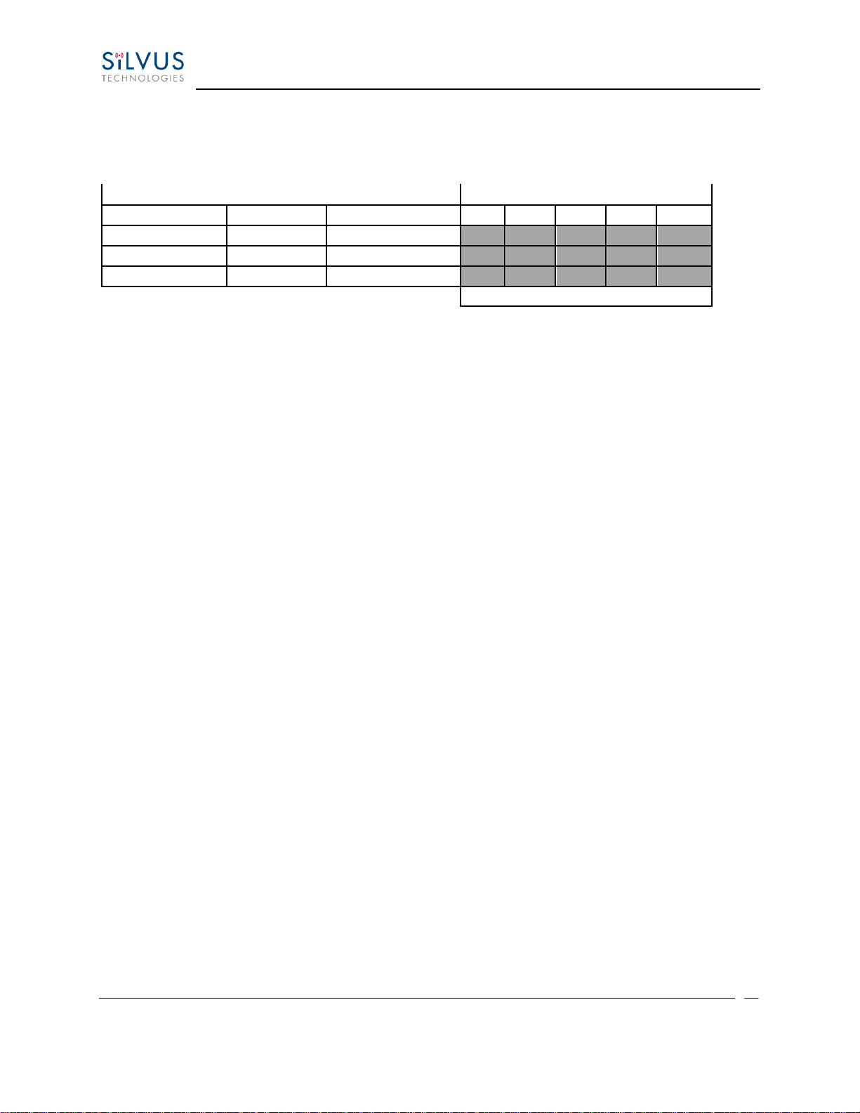
Antenna
Transmitter Power
Type
Gain (dBi)
Gain Ratio (GR)
1W
2W
4W
10W
30W
Omni
3
2
0.4
0.6
0.8
1.3
2.2
Sector
20
100
2.9
4
5.6
9
15.5
Parabolic Dish
35
3162
16
22.5
32
50
87
Minimum Safe Distance (Meters)
Table 1 Safe Working Distances
General Safety Notes
•A flashing/steady Red LED status indication is a normal condition, and is not meant to
convey a fault condition.
•The Power Disconnect Device for the product is the connector for the external AC/DC
Adapter or other DC power source.
•Although the Low Voltage DC powered units are approved for Outdoor use
(Dust/Temporary Immersion), the optional AC power option with AC/DC power supply is
only certified for indoor use.
•The unit housing serves as a heatsink, and must be mounted on a non-combustible
surface.
•The units are not User Serviceable. Contact the manufacturer for further instructions on
servicing or repair.
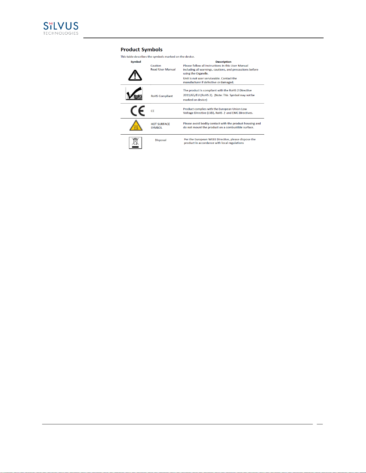
•All symbols, markings and warning statements marked on the equipment are shown
below for reference.
StreamCaster MIMO Radio User Manual 4/30/19
10017C000 Silvus Technologies Confidential Page
13
Figure 1 Product Symbols with Definition
•Product cleaning should only be done with a soft cloth and mild detergent, do not use any
solvents that might remove case markings or labels.
•The unit, at the end of its useful life is to be disposed in accordance with local regulations,
or may be returned to the manufacturer.
•If the equipment is used in a manner not specified by the manufacturer, the protection
provided by the equipment and/or equipment performance may be impaired.

StreamCaster MIMO Radio User Manual 4/30/19
10017C000 Silvus Technologies Confidential Page
14
1.2 Maximum RF Power Density Limits
The RF Radiation Power Density limit figure recommended by Silvus is based upon guideline levels
published in:
a. IEEE standard C95.1 1999 - IEEE Standard for Safety Levels with respect to Human Exposure to Radio
Frequency Electromagnetic Fields, 3 kHz to 300 GHz.
b. Guidelines for Limiting Exposure to Time-varying Electric, Magnetic & Electromagnetic Fields (up to 300
GHz) published in 1998 by the Secretariat of the International Commission on Non-Ionizing Radiation
Protection (ICNIRP).
Both documents define guideline RF power density limits for "Controlled" and "Uncontrolled"
environments. An uncontrolled environment is defined as one in which the person subjected to the RF
radiation may be unaware of and has no control over the radiation energy received. The uncontrolled
environment conditions can arise, even in the best regulated operations and for this reason the limits
defined for the uncontrolled environment have been assumed for the RF Central recommended limit.
Documents a) and b) also show the RF power density guidelines to be frequency dependent. Different
power density / frequency characteristics are presented in the two documents. To avoid complexity and
to avoid areas of uncertainty, Silvus recommends the use of a single power density limit across the
frequency range 100 kHz to 300 GHz. The 1w/m² power density limit we recommend satisfies the most
stringent of the guidelines published to date.
Footnote: The IICNIRP document may be freely downloaded from the internet at
www.icnirp.de/documents/emfgdl.pdf (PDF file).

StreamCaster MIMO Radio User Manual 4/30/19
10017C000 Silvus Technologies Confidential Page
15
2. Introduction
The StreamCaster family of MIMO radios was designed with operator ease of use in mind. Each radio is
capable of operating in a multitude of configurations that are accessed via simple web pages within the
radio. Settings such as transmit power, frequency, channel bandwidth, link adaptation and range control
can be accessed by simply using a web browser to log into any radio within the network. This quick start
user guide contains all essential information for the user to configure the StreamCaster radio as well as
how to run an iperf network test.
3. StreamCaster Network
Each StreamCaster MIMO radio has a fixed static IP address in the 172.20.xx.yy network. The
radio operates as a network switch; the user equipment does not need to be on the same subnet
as the radio during operation. It is possible to setup a secondary IP address on the radio if the
user finds this feature convenient. Setting up a secondary IP address is useful if the user wishes
to access the radio’s web interface in their network.
StreamCaster MIMO Radio User Manual 4/30/19
10017C000 Silvus Technologies Confidential Page
16
4. StreamCaster Hardware Overview
4.1 Hardware Interfaces
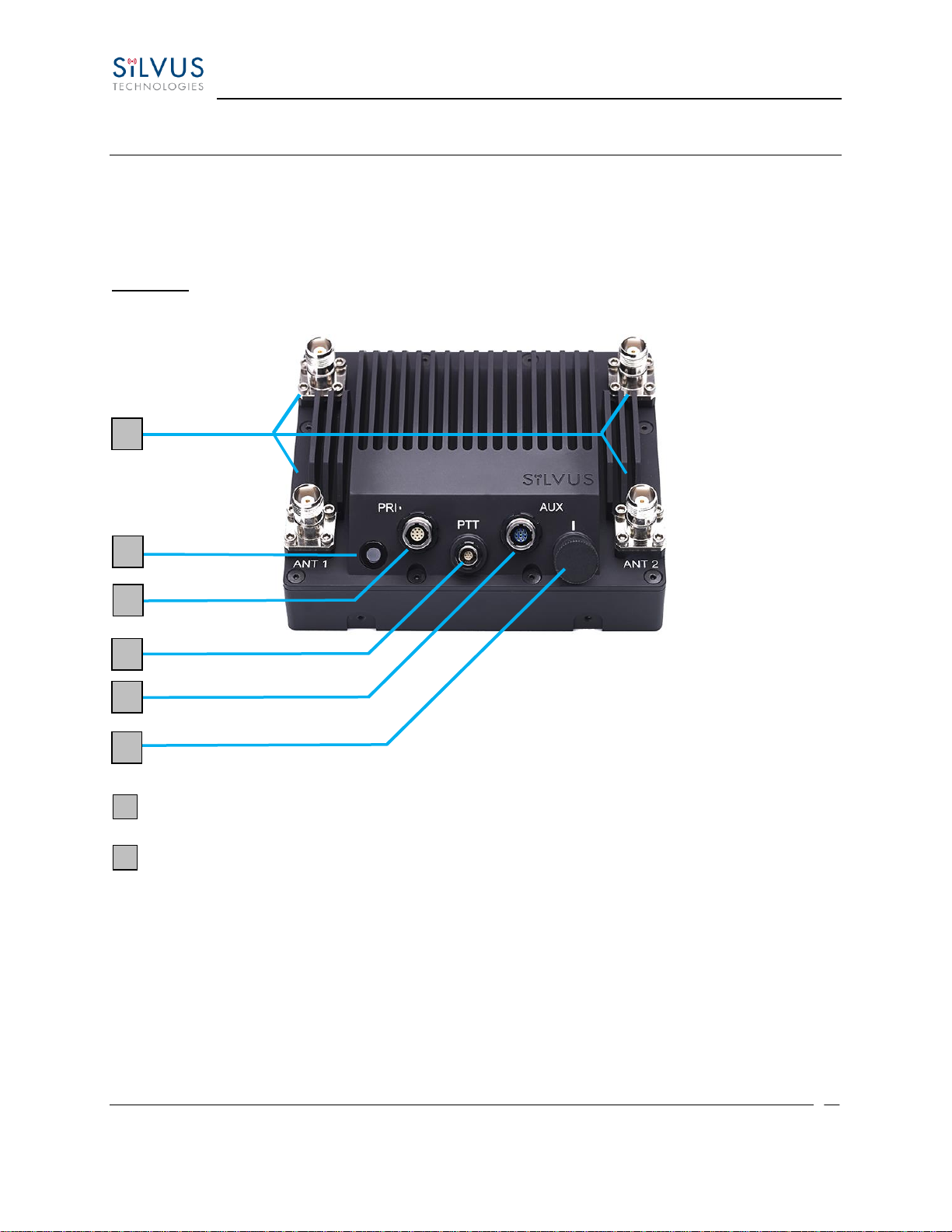
SC4400E
Figure 2 StreamCaster 4400E Ruggedized Enclosure
RF Channels 1-4 Connectors [TNC Female]
Bi-Color Status LED (See Section 12.1 for Troubleshooting Information)
•Red –Radio is in the process of booting up
•Flashing Green –Radio is fully booted but not wirelessly connected to any other
radio
•Green –Radio is wirelessly connected to at least one other radio
•Flashing Red –Spectrum Scan in Progress
•Flashing Red –Radio has recovered from a bad state and has reverted to factory
default settings.
1
2
1
2
3
4
5
6

StreamCaster MIMO Radio User Manual 4/30/19
10017C000 Silvus Technologies Confidential Page
17
•Rapid Flashing Red for 1 second –The battery is less than or equal to 20%. LED
will blink red rapidly for 1 second then go back to normal. This will repeat every
5 seconds.
•Rapid Flashing Green –When the multi position switch is rotate to a new
position, LED will rapidly flash green while new settings are being applied. LED
will resume normal indication after settings have been applied.
Power (9-20V), Ethernet, and Serial Port Connector [ODU GK0YAR-P10UC00-000L]
Push-to-Talk (PTT) Connector [ODU GKCWAM-P07UB00-000L]
AUX Connector [ODU GK0YCR-P10UC00-000L]
Power Switch [15-Position Rotating]
3
4
5
6
StreamCaster MIMO Radio User Manual 4/30/19
10017C000 Silvus Technologies Confidential Page
18
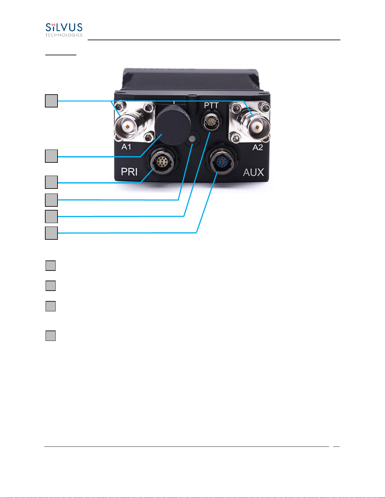
SC4200E
Figure 3 StreamCaster 4200E Ruggedized Enclosure
RF Channels 1-2 Connectors [TNC Female]
Power Switch [15-Position Rotating]
Power (EB Version Only, 9-20V), Ethernet, and Serial Port Connector [ODU GK0YAR-
P10UC00-000L]
Bi-Color Status LED (See Section 12.1 for Troubleshooting Information)
•Red –Radio is in the process of booting up
•Flashing Green –Radio is fully booted but not wirelessly connected to any other
radio
•Green –Radio is wirelessly connected to at least one other radio
•Flashing Red –Spectrum Scan in Progress
•Flashing Red –Radio has recovered from a bad state and has reverted to factory
default settings.
1
2
3
4
1
2
3
4
5
6

StreamCaster MIMO Radio User Manual 4/30/19
10017C000 Silvus Technologies Confidential Page
19
•Rapid Flashing Red for 1 second –The battery is less than or equal to 20%. LED
will blink red rapidly for 1 second then go back to normal. This will repeat every
5 seconds.
•Rapid Flashing Green –When the multi position switch is rotate to a new
position, LED will rapidly flash green while new settings are being applied. LED
will resume normal indication after settings have been applied.
Push-to-Talk (PTT) Connector [ODU GKCWAM-P07UB00-000L]
AUX Connector [ODU GK0YCR-P10UC00-000L]
5
6
This manual suits for next models
11
Table of contents
Other Silvus Radio manuals


Popular Radio manuals by other brands

Pure Digital
Pure Digital Elan RV40 owner's manual

Motorola
Motorola ASTRO APX O2 Control Head Mobile Radio user manual

Cobra
Cobra 29 LX BT CB operating instructions

AUDIOLINE
AUDIOLINE PMR easy 009 operating instructions

Sirius Satellite Radio
Sirius Satellite Radio STILETTO 10 100306B user guide

Alcatel
Alcatel MDR-8000 user manual


