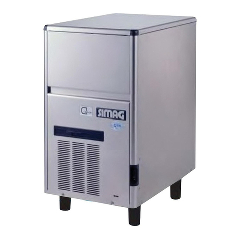
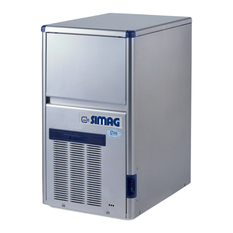
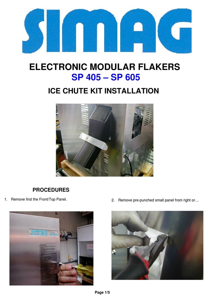
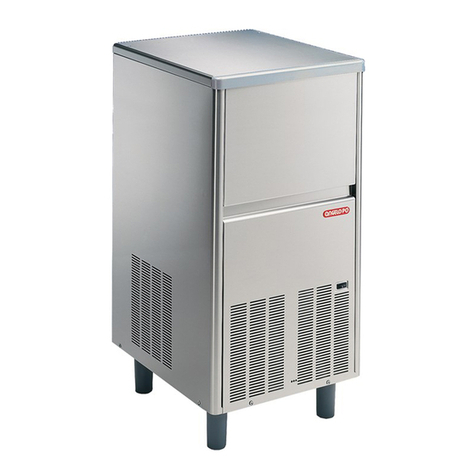
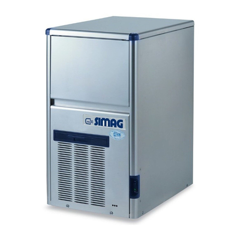
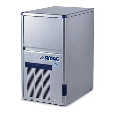
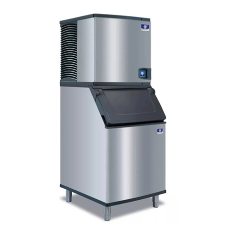
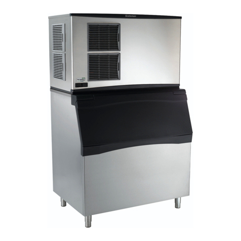
SIMAG SPN 125 User manual

SERVICE MANUAL
SPN 125
SPN 255
SPN 405
SPN 605
SPN 1205
R 134A-R 404 A VERSION
NEW PC BOARD
SPN 125 from Serial Number ZA 2658
\ SPN 255 from Serial Number ZB 3204
SPN 405 from Serial Number ZC 2237
Electronic mo SPN 605 from Serial Number ZD 2193
SPN 125 from Serial Number ZA 2658 SPN 1205 from Serial Number ZE 1164
REV. 09.2013
EV
Rev. 09/2012

LED STATUS REASON WHY – SIGNIFICATION – SIGNIFICATO – Beschreibung
ON STEADY
FIXE
FISSO
Ständig an
UNIT OFF AT BIN FULL
CABINE PLAINE
CONTENITORE PIENO
Maschine AUS, Speicher voll!
BLINKING SLOW
CLIGNOTANT LENT
LAMPEGG. LENTO
Blinkt langsam
I/R BEAM CUTTED
FAISCEAU INFRA ROUGE CELLULE NIVEAU GLACE INTERROMPU
RAGGIO INFRAROSSO INTERROTTO
Lichtschranke unterbrochen!
BLINKING FAST
CLIGNOTANT RAPIDE
LAMPEGG. VELOCE
Blinkt schnell
I/R ON AFTER TRIP OFF AT BIN FULL
FAISCEAU INFRA ROUGE CELLULE NIVEAU GLACE ETABLI
RAGGIO INFRAROSSO RIPRISTINATO INTERROTTO
Speicher entleert, Maschine startet gleich!
ON STEADY
FIXE
FISSO
Ständig an
NO WATER
MANQUE D’EAU
MANCANZA ACQUA
Kein Wasser!
ON STEADY
FIXE
FISSO
Ständig an
TOO HI DISCHARGE PRESSURE/TEMP OR TO LOW ROOM TEMP (< +3°C)
COUPURE HP OU TRES BASSE TEMP. AMBIANTE (< +3°C)
FERMATA ALTA TEMP. CONDENSAZIONE O TEMP. AMBIENTE BASSA (< +3°C)
Zu hoher Kondensationsdruck oder Raumtemp. < +3°C!
BLINKING
CLIGNOTANT
LAMPEGGIANTE
Blinkt
DELAY AT START UP (3
min. or 60 min. according to the Jumper setting)
TEMPORISATION AU DEMARRAGE (3 min ou 60 min. selon le reglage du chavalier)
RITARDO PARTENZA (3' o 60’ in funzione della regolazione del ponticello)
3 min. oder 60 min. Startverzögerung je nach Jumper Konfig.!
ON STEADY
FIXE
FISSO
Ständig an
NO, SLOW OR WRONG ROTATION OF DRIVE MOTOR
MOTOREDUCTEUR TOURNE A L'ENVERS, NE TOURNE PAS, OU TROP LENTEMENT
MOTORE RIDUTTORE GIRA AL CONTRARIO, NON GIRA O GIRA LENTAMENTE
Keine, zu langsame oder schwere Getriebrotation!
BLINKING
CLIGNOTANT
LAMPEGGIANTE
Blinkt
TOO HI EVAP. TEMP. (> 0C°) AFTER 10' FROM START UP
OR TOO LOW EVAP. TEMP. (< -25°C)
COUPURE TEMP. EVAP. >0°C APRES 10' DE FONCTIONNEMENT OU TEMP. EVAP. <-25°C
TEMP. EVAP >0 °C DOPO 10' DA INIZIO FUNZIONAMENTO O INFERIORE A -25°C
Zu hohe Verd.temp. > 0°C 10 min. nach dem Start oder zu niedrige Verd.temp. < -25°C
ON STEADY
FIXE
FISSO
Ständig an
BLINKING
CLIGNOTANT
LAMPEGGIANTE
Blinkt
CONDENSER SENSOR OUT OF ORDER
SONDE CONDENSEUR HS
SONDA CONDENSATORE MALFUNZIONANTE
Kondensatorfühler defekt!
EVAPORATOR SENSOR OUT OF ORDER
SONDE EVAPORATEUR HS
SONDA EVAPORATORE MALFUNZIONANTE
Verdampferfühler defekt!
BLINKING ALTERNATE
CLIGNOTANT ALTERNE’
LAMPEGGIANTE ALTERNATO
Blinkt im Wechsel!
OPTICAL ICE LEVEL CONTROL OUT OF ORDER
CELLULE INFRAROUGE NIVEAU GLACE HS
SONDA ALL’INFRAROSSO LIVELLO GHIACCIO MALFUNZIONANTE
Lichtschranke defekt!
BLINKING
CLIGNOTANT
LAMPEGGIANTE
Blinkt
6 OR 12 MONTHS WATER SYSTEM CLEANING REMIND (according to the Jumper setting)
RAPPEL NETTOYAGE SYSTÉME HYDAULIQUE APRÉS 6 OU 2 MOIS (selon reglage. chavalier)
RICHIAMO PULIZIA CIRCUITO IDRICO DOPO 6 O 12 MESI (In funzione regolazione ponticello)
6 oder 12 Monate Reinigungshinweis für Wassersystem je nach Jumper Konfig.!
BLINKING IN SEQUENCE
CLIGNOTTANT EN SEQUENCE
LAMPEGGIANTE IN SEQUENZA
Blinken nacheinander!
PURGE CYCLE IN OPERATION (Only on units equipped with purge valve)
CYCLE D’ÉVACUATION EAU EN FONCTION (Seulement dans les machine equipées avec vanne devidange eau)
SISTEMA SCARICO ACQUA IN FUNZIONE (Solo negli apparecchi dotati di valvola di scarico)
Spülzyklus läuft, bei Maschinen mit Ablaßventil!
BLINKING
CLIGNOTANT
LAMPEGGIANTE
Blinken
UNIT OFF DUE TO THE JUMPER ON TEST CONTACTS
MACHINE A L’ÂRRET – CONTACTS TEST FERMÉES
MACCHINA FERMA – CONTATTI TEST CHIUSI
Jumper Konfig. Im Testmodus!
PUSH AND HOLD THE RED LIGHTED SWITCH OR THE PC BOARD BUTTON FOR MORE OF 5 SECONDS WITH MACHINE IN OPERATION
TILL THE SWITCHING OFF OF THE TWO YELLOW LEDS TO RESTART THE CLEANING REMIND COUNTDOWN
APPUYER SUR LE BOUTON ROUGE OU SUR LE BOUTON DE LA CARTE POUR 5 SECONDES AVEC LA MACHINE EN FONCTIONNEMENT
JUSQU’A L’ETEINTE DE LES DEUX LEDS JAUNE POUR REINITIALISER L'ALARME JUSQU'AU PROCHAIN DETARTRAGE
PREMERE IL PULSANTE ROSSO O IL PULSANTE DELLA SCHEDA PER PIU' DI 5" CON LA MACCHINA IN FUNZIONE FINO ALLO
SPEGNIMENTO DEI DUE LED GIALLI PER FAR RIPARTIRE IL CONTEGGIO PER LA PROSSIMA DISINCROSTAZIONE
Drücken und halten Sie den roten Schalter oder den push button auf der Elektronik, für mehr als 5 Sekunden wenn die Maschine in Betrieb ist, bis
die 2 gelben LED´s auf der Elektronik nicht mehr leuchten!
Der Erinnerungszyklus für die Reinigung ist somit zurückgesetzt und startet neu!

TABLE OF
CONTENTS
1
2
4
6
8
10
Page 1
Table of contents page
Specifications SPN 125
Specifications SPN 255
Specifications SPN 405
Specifications SPN 605
Specifications SPN 1205
GENERAL INFORMATION AND INSTALLATION
Introduction
Unpacking and Inspection - Ice maker
Unpacking and Inspection - Storage bin
Location and levelling
Electrical connections
Water supply and drain connections
Final check list
Installation practice
OPERATING INSTRUCTIONS
Start up
Operational checks
PRINCIPLE OF OPERATION (How it works)
Water circuit
Refrigerant circuit
Mechanical system
Operating pressures
Components description
ADJUSTMENT, REMOVAL AND REPLACEMENT PROCEDURES
Adjustment of the evaporator water level
Replacement of the Gear Motor Magnetic Sensor
Replacement of the auger, water seal, bearings and coupling
Replacement of the gear motor assy
Replacement of the freezing cylinder
Wiring diagram SPN 125 - 255
Wiring diagram SPN 405 - 605 single phase
Wiring diagram SPN 405 three phase
Wiring diagram SPN 1205 three phase
Service diagnosis
MAINTENANCE AND CLEANING INSTRUCTIONS
General
Icemaker
Cleaning instructions of water system
12
12
12
13
14
14
14
15
16
18
21
22
24
25
26
30
30
30
32
32
33
34
35
36
37
39
39
39

SPECIFICATIONS
ice making capacity
ELECTRONIC MODULAR FLAKER MODEL SPN 125
Important operating requirements:
MIN MAX
• Air temperature 10°C (50°F) 40°C (100°F)
• Water temperature 5°C (40°F) 35°C (90°F)
• Water pressure 1 bar (14 psi) 5 bars (70 psi)
• Electr. voltage
• variations from voltage
• rating specified
• on nameplate -10% +10%
NOTE. The daily ice-making capacity is directly related to the condenser air inlet temperature, water
temperature and age of the machine.
To keep your SIMAG FLAKER at peak performance levels, periodic maintenance checks
must be carried out as indicated on maintenance section of this manual.
Page 2
Kg.
32 °C27 21 15 10
°C
10
21
o
o
32
38
120
115
110
105
100
95
90
85
80
Kg.
32 °C27 21 15 10
°C
10
21
o
o
32
38
120
115
110
105
100
95
90
85
80
ICE PRODUCED PER 24 HRS.
AIR COOLED MODELS
WATER TEMPERATURE
AMBIENT TEMPERATURE
ICE PRODUCED PER 24 HRS.
WATER COOLED MODELS
WATER TEMPERATURE
AMBIENT TEMPERATURE

SPN 125 AS Air 120*
SPN 125 WS Water 480*
Start Electric power cons.
Amps Kwh per 24 HR
SPECIFICATIONS
Water req.
lt/24 HR
Model Finish
Cond. unit Comp. HP
* A 15°C water temperature
S. Steel 3/8
Basic electr. Amps Watts Nr. of wires Amps fuse
230/50/1 3.2 17 500 11 3 x 1.5 mm210
SPN 125 - MACHINE SPECIFICATIONS
Page 3
Dimensions:
HEIGHT (less legs) 525 mm.
HEIGHT (with legs) 542 mm.
WIDTH 563 mm.
DEPTH 536 mm.
WEIGHT 49 Kg.

SPECIFICATIONS
ice making capacity
ELECTRONIC MODULAR FLAKER MODEL SPN 255
Important operating requirements:
MIN MAX
• Air temperature 10°C (50°F) 40°C (100°F)
• Water temperature 5°C (40°F) 35°C (90°F)
• Water pressure 1 bar (14 psi) 5 bars (70 psi)
• Electr. voltage
• variations from voltage
• rating specified
• on nameplate -10% +10%
NOTE. The daily ice-making capacity is directly related to the condenser air inlet temperature, water
temperature and age of the machine.
To keep your SIMA G FLAKER at peak performance levels, periodic maintenance checks
must be carried out as indicated on maintenance section of this manual.
200
180
160
140
120
Kg.
32 °C27 21 15 10
°C
10
21
o
o
32
38
190
180
170
160
150
Kg.
32 °C27 21 15 10
DE 10 A 38°C
o
AIR COOLED MODELS
WATER TEMPERATURE
AMBIENT TEMPERATURE
ICE PRODUCED PER 24 HRS.
WATER COOLED MODELS
WATER TEMPERATURE
AMBIENT TEMPERATURE
ICE PRODUCED PER 24 HRS.
Page 4

SPN 255 AS Air 200*
SPN 255 WS Water 850*
Start Electric power cons.
Amps Kwh per 24 HR
SPECIFICATIONS
Water req.
lt/24 HR
Dimensions:
HEIGHT (less legs) 525 mm.
HEIGHT (with legs) 542 mm.
WIDTH 563 mm.
DEPTH 536 mm.
WEIGHT 49 Kg.
Model Finish
Cond. unit Comp. HP
* A 15°C water temperature
S. Steel 5/8
Basic electr. Amps Watts Nr. of wires Amps fuse
230/50/1 4 20 760 17 3 x 1.5 mm210
SPN 255 - MACHINE SPECIFICATIONS
Page 5

SPECIFICATIONS
ice making capacity
ELECTRONIC MODULAR SUPERFLAKER
MODEL SPN 405
Important operating requirements:
MIN MAX
• Air temperature 10°C (50°F) 40°C (100°F)
• Water temperature 5°C (40°F) 35°C (90°F)
• Water pressure 1 bar (14 psi) 5 bars (70 psi)
• Electr. voltage
• variations from voltage
• rating specified
• on nameplate -10% +10%
NOTE. The daily ice-making capacity is directly related to the condenser air inlet temperature, water
temperature and age of the machine.
To keep your S IMA G FLAKER at peak performance levels, periodic maintenance checks
must be carried out as indicated on maintenance section of this manual.
Page 6
310
330
310
290
270
250
230
210
190
Kg.
°C27 21 15 10
°C
10
21
o
o
32
38
360
340
320
300
280
260
240
220
200
Kg.
32 °C27 21 15 10
°C
10
21
32
38
o
o
AIR COOLED MODELS
WATER TEMPERATURE
AMBIENT TEMPERATURE
ICE PRODUCED PER 24 HRS.
WATER COOLED MODELS
WATER TEMPERATURE
AMBIENT TEMPERATURE
ICE PRODUCED PER 24 HRS.
32

SPECIFICATIONS
Start Electric power cons.
Amps Kwh per 24 HR
Water req.
lt/24 HR
SPN 405 - MACHINE SPECIFICATIONS
Dimensions:
HEIGHT (less legs) 645 mm.
HEIGHT (with legs) 650 mm.
WIDTH 535 mm.
DEPTH 660 mm.
WEIGHT 77 Kg.
Model Finish
Cond. unit Comp. HP
* A 15°C water temperature
SPN 405 AS Air 320*
SPN 405 WS Water 1800*
S. Steel 1
Basic electr. Amps Watts Nr. of wires Amps fuse
230/50/1 5.2 29 1200 26 3 x 1.5 mm 16
2
Page 7

SPECIFICATIONS
ice making capacity
ELECTRONIC MODULAR SUPERFLAKER
MODEL SPN 605
NOTE. The daily ice-making capacity is directly related to the condenser air inlet temperature, water
temperature and age of the machine.
To keep your SIMA G FLAKER at peak performance levels, periodic maintenance checks
must be carried out as indicated on maintenance section of this manual.
Page 8
Important operating requirements:
MIN MAX
• Air temperature 10°C (50°F) 40°C (100°F)
• Water temperature 5°C (40°F) 35°C (90°F)
• Water pressure 1 bar (14 psi) 5 bars (70 psi)
• Electr. voltage
• variations from voltage
• rating specified
• on nameplate -10% +10%
700
650
600
550
500
450
400
350
300
Kg.
32 °C27 21 15 10
°C
10
21
o
o
32
38
600
575
550
525
500
475
450
425
400
Kg.
°C
°C
10
21
32
38
o
o
AIR COOLED MODELS
WATER TEMPERATURE
AMBIENT TEMPERATURE
ICE PRODUCED PER 24 HRS.
WATER COOLED MODELS
WATER TEMPERATURE
AMBIENT TEMPERATURE
ICE PRODUCED PER 24 HRS.
32 27 21 15 10

Basic electr. Amps Watts Nr. of wires Amps fuse
2000
230/50/1 10 34 45 3 x 1.5 mm2 16
400/50/3+N 4 22 40 5 x 1.5 mm2 16
SPECIFICATIONS
Start Electric power cons.
Amps Kwh per 24 HR
Water req.
lt/24 HR
SPN 605 - MACHINE SPECIFICATIONS
Dimensions:
HEIGHT (less legs) 785 mm.
HEIGHT (with legs) 790 mm.
WIDTH 535 mm.
DEPTH 660 mm.
WEIGHT 93 Kg.
Model Finish
Cond. unit Comp. HP
* A 15°C water temperature
S. Steel
SPN 605 AS Air 600*
SPN 605 WS Water 3000*
Page 9
1.5

SPECIFICATIONS
ice making capacity
ELECTRONIC MODULAR SUPERFLAKER
MODEL SPN 1205
Important operating requirements:
MIN MAX
• Air temperature 10°C (50°F) 40°C (100°F)
• Water temperature 5°C (40°F) 35°C (90°F)
• Water pressure 1 bar (14 psi) 5 bars (70 psi)
• Electr. voltage
• variations from voltage
• rating specified
• on nameplate -10% +10%
NOTE. The daily ice-making capacity is directly related to the condenser air inlet temperature, water
temperature and age of the machine.
To keep your SIMA G FLAKER at peak performance levels, periodic maintenance checks
must be carried out as indicated on maintenance section of this manual.
Page 10
1150
1100
1050
1000
950
900
850
800
750
700
Kg.
32 °C21 15 10
°C
10
21
o
32
38
1400
1300
1200
1100
1000
900
800
700
600
500
Kg.
°C
°C
DE 10 A 38°C
o
32
38
AIR COOLED MODEL
WATER TEMPERATURE
AMBIENT TEMPERATURE
ICE PRODUCED PER 24 HRS.
WATER COOLED MODELS
WATER TEMPERATURE
AMBIENT TEMPERATURE
ICE PRODUCED PER 24 HRS.
27 32 21 15 1027

SPN 1205 AS Air 1150*
SPN 1205 WS Water 8000*
Basic electr. Amps Watts Nr. of wires Amps fuse
230/50/3 7,1 56 4 x 2.5 mm 25
400/50/3 + N 3,4 28 5 x 2.5 mm 16
3600 80
SPECIFICATIONS
Start Electric power cons.
Amps Kwh per 24 HR
Water req.
lt/24 HR
SPN 1205 - MACHINE SPECIFICATIONS
Dimensions:
HEIGHT 850 mm.
WIDTH 1065 mm.
DEPTH 698 mm.
WEIGHT 179 Kg.
Model Finish
Cond. unit Comp. HP
* A 15°C water temperature
S. Steel 2.5
2
2
Page 11

GENERAL INFORMATION AND INSTALLATION
A. INTRODUCTION
This manual provides the specifications and the
step-by-stepproceduresfortheinstallation,start-
upandoperation,maintenanceandcleaningfor
the SIMAGSPN 125-255-405-605
and SPN 1205 Modular Icemakers.
The Electronic Flakers and Superflakers are
qualitydesigned,engineeredandmanufactured.
Their ice making systems are thoroughly tested
providing the utmost in flexibility to fit the needs
of a particular user.
4. OnmodelsSPN 125,255,405 andSPN 605
remove the top and front panel while on model
SPN 1205 remove top and sides panels of the unit
and inspect for any concealed damage. Notify
carrier of your claim for the concealed damage
as stated in step 2 above.
5. Remove all internal support packing and
masking tape.
6. Check that refrigerant lines do not rub
againstortouchotherlinesorsurfaces,andthat
the fan blades move freely.
7. Checkthatthecompressorfitssnuglyonto
all its mounting pads.
8. See data plate on the rear side of the unit
and check that local main voltage corresponds
with the voltage specified on it.
CAUTION. Incorrect voltage supplied to
the icemaker will void your parts
replacement program.
9. Remove the manufacturer’s registration
card from the inside of the User Manual and fill-
in all parts including: Model and Serial Number
taken from the data plate.
Forwardthecompletedself-addressedregistra-
tion card to SIMAG/Frimont Spa
factory.
Storage bin (R Series)
1. Follow the steps 1, 2 and 3 above to
unpack the storage bin.
2. Unloosethetwoboltsandremovetheprotec-
tionplatefromthedrainfittingonmodelR250.
3. Carefully lay it down on its rear side and fit
the four legs into their sockets.
4. Remove all internal support packing and
masking tape as well as the plastic ice cube
deflectorwhichisnotusedwiththeSIMAG
Modular Flakers.
5. Remove the manufacturer’s registration
card from the inside of the User Manual and fill-
in all parts including: Model and Serial Number
taken from the data plate.
Forwardthecompletedself-addressedregistra-
tion card to SIMAG/Frimont Spa
factory.
.
.
.
NOTE.Toretainthesafetyandperformance
built into this icemaker, it is important that
installation and maintenance be conducted
in the manner outlined in this manual.
Storage Bin
SincetheSPN seriesModularFlakersdonothave
theirownattachedicestoragebins,itisnecessary
to use an auxiliary bin as detailed here below:
R 100 or R 130 in combination with
SPN 125 and SPN 255
R 150 or R 190 with its companion
CBT 30 EFSD Top Cover in combination with
SPN 125, SPN 255, SPN 405 and SPN 605
R 250 withitscompanionCBT42EFSD
TopCoverincombinationwithSPN 405 and605
R 300 withitscompanionCBT48FMCD
TopCoverincombinationwithSPN 405 and605
R 400 withitscompanionCBT52FMCD
in combination with SPN 405 and SPN 605
B. UNPACKING AND INSPECTION
Icemaker
1. CallyourauthorizedSIMAGDistributor
or Dealer for proper installation.
2. Visually inspect the exterior of the packing
and skid. Any severe damage noted should be
reportedtothedeliveringcarrierandaconcealed
damageclaimformfilledinsubjettoinspectionof
the contents with the carrier’s representative
present.
3. a)Cutandremovetheplasticstripsecuring
the carton box to the skid.
b)Cutopenthetopofthecartonandremovethe
polystyre protection sheet.
c) Pull out the polystyre posts from the corners
and then remove the carton.
Page 12

3. On R Series Storage Bin inspect its top
mounting gasket which should be flat with no
wrinkles, to provide a good sealing when the
CBT Top Cover is installed on top of it.
4. Place the CBT Top Cover on top of Storage
bin using care not to wrinkle or tear the gasket.
5On the UBH Series Storage Bin unloose
the screws securing the S.S. Top Cover to the
storage bin and remove it
6. Lay out on the bin top the plan of the ice
machine as it will be located on the bin and cut an
opening in the bin top for the ice drop area; cover
the edges of the opening with vinyl tape.
7. Install the gasket-on the bin top-around ice
drop opening of the bin top; apply sealant along
the inside of the gasket.
8. Position and install the four aluminium front
to rear stiffeners (U shaped) paying attention to
the guideline shown on the drawing.
NOTE. Bin wall gasket must be cut to clear
the stiffener ends as shown on drawing.
Do not put any stiffeners crossing the ice
drop opening.
9. Install the bin top in its position onto the bin
top by:
- place the rear side of top against rear edge
of the bin
- lower the front of the top onto the stiffeners
- re-fit the screws previously removed as
per step 5
10. Install the Modular Flaker or Superflaker
onto the Top Cover of storage bin pay attention
to match the ice chute with the Bin Top opening.
D. ELECTRICAL CONNECTIONS
See data plate for current requirements to
determine wire size to be used for electrical
connections. All SIMAG icemakers require
a solid earth wire.
All SIMAG ice machines are supplied from
the factory completely pre-wired and require only
electrical power connections to the wire cord
provided at the rear of the unit.
CBT Top Covers
1. Follow the steps 1 and 2 above to unpack
the top cover.
2. Cut open the carton box and pull out the
CBT Top Cover.
3. On CBT 48/52 FMCD Top Covers, the ice
drop area must be cutted on the plastic cover in
the same position of the ice machine ice chute
opening.
C. LOCATION AND LEVELLING
WARNING. This Modular Flaker and
Superflaker is designed for indoor
installation only. Extended periods of
operation at temperature exceeding the
following limitations will constitute
misuse under the terms of the SIMAG
Manufacturer’s Limited Warranty resulting
in LOSS of warranty coverage.
1. Position the storage bin in the selected
permanent location.
Criteria for selection of location include:
a) Minimum room temperature 10°C (50°F)
and maximum room temperature 40°C (100°F).
b) Water inlet temperatures: minimum 5°C
(40°F) and maximum 35°C (90°F).
c) Well ventilated location for air cooled
models (clean the air cooled condenser at
frequent intervals).
d) Service access: adequate space must be
left for all service connections through the rear of
the ice maker. A minimum clearance of 15 cm
(6") must be left at the sides of the unit for routing
cooling air drawn into and exhausted out of the
compartment to maintain proper condensing
operation of air cooled models.
2. Level the Storage Bin Assy in both the left
to right and front to rear directions by means of
the adjustable legs.
STIFFENER
CUT GASKET HERE
BIN WALL GAKET
TOP SHELL
Page 13

Make sure that the ice machine is connected to
its own circuit and individually fused (see data
plate for fuse size).
The maximum allowable voltage variation should
not exceed -10% and +10% of the data plate
rating. Low voltage can cause faulty functioning
and may be responsible for serious damage to
the overload switch and motor windings.
NOTE. All external wiring should conform to
national, state and local standards and
regulations.
Check voltage on the line and the ice maker’s
data plate before connecting the unit.
E. WATER SUPPLY AND DRAIN
CONNECTIONS
GENERAL
When choosing the water supply for the ice flaker
consideration should be given to:
a) Length of run
b) Water clarity and purity
c) Adequate water supply pressure
Since water is the most important single ingredient
in producting ice you cannot emphasize too
much the three items listed above.
Low water pressure, below 1 bar may cause
malfunction of the ice maker unit.
Water containing excessive minerals will tend to
produce scale build-up on the interior parts of the
water system while too soft water (with too lo
contents of mineral salts), will produce a very
hard flaker ice.
WATER SUPPLY
Connect the 3/4" GAS male of the water inlet
fitting, using the food grade flexible hose supplied
to the cold water supply line with regular plumbing
fitting and a shut-off valve installed in an
accessible position between the water supply
line and the unit.
If water contains a high level of impurities, it is
advisable to consider the installation of an
appropriate water filter or conditioner.
WATER SUPPLY - WATER COOLED MODELS
The water cooled versions of SIMAG Ice
Makers require two separate inlet water supplies,
one for the water making the flaker ice and the
other for the water cooled condenser.
Connect the 3/4" GAS male fitting of the water
inlet, using the flexible hose supplied to the cold
water supply line with regular plumbing fitting
and a shut-off valve installed in an accessible
position between the water supply line and the
unit.
WATER DRAIN
The recommended drain tube is a plastic or
flexible hose with 18 mm (3/4") I.D. which runs to
an open trapped and vented drain. When the
drain is a long run, allow 3 cm pitch per meter
(1/4" pitch per foot).
Install a vertical open vent on drain line high point
at the unit drain connection to ensure good
draining.
The ideal drain receptacle is a trapped and vented
floor drain.
WATER DRAIN - WATER COOLED MODELS
Connect the 3/4" GAS male fitting of the condenser
water drain, utilizing a second flexible hose to the
open trapped and vented drain.
This additional drain line must not interconnect to
any other of the units drains.
NOTE. The water supply and the water drain
must be installed to conform with the local
code. In some case a licensed plumber and/
or a plumbing permit is required.
F. FINAL CHECK LIST
1. Is the unit in a room where ambient
temperatures are within a minimum of 10° C (50°F)
even in winter months?
2. Is there at least a 15 cm (6") clearance
around the unit for proper air circulation?
3. Is the unit level? (IMPORTANT)
4. Have all the electrical and plumbing
connections been made, and is the water supply
shut-off valve open?
5. Has the voltage been tested and checked
against the data plate rating?
6. Has the water supply pressure been checked
to ensure a water pressure of at least 1 bar (14
psi).
7. Have the bolts holding the compressor down
been checked to ensure that the compressor is
snugly fitted onto the mounting pads?
8. Check all refrigerant lines and conduit lines
to guard against vibrations and possible failure.
9. Have the bin liner and cabinet been wiped
clean?
10. Has the owner/user been given the User
Manual and been instructed on the importance of
periodic maintenance checks?
11. Has the Manufacturer’s registration card
been filled in properly? Check for correct model
and serial number against the serial plate and
mail the registration card to the factory.
12. Has the owner been given the name and the
phone number of the authorized SIMAG
Service Agency serving him?
Page 14

G. INSTALLATION PRACTICE
1. Hand shut-off valve
2. Water filter
3. Water supply line (flexible hose)
4. 3/4" GAS male fitting
5. Power line
6. Main switch
7. Drain fitting
8. Vented drain
9. Vented drain
10. Open trapped vented drain
WARNING. This icemaker is not designed for outdoor installation and will not function in
ambient temperatures below 10°C (50°F) or above 40°C (100°F).
This icemaker will malfunction with water temperatures below 5 °C (40°F) or above 35 °C
(90°F).
Page 15

OPERATING INSTRUCTIONS
START UP
After having correctly installed the ice maker and
completed the plumbing and electrical
connections, perform the following “Start-up” pro-
cedure.
A. Open the water supply line shutoff valve
and put the unit under electrical power by moving
the main switch, on the power supply line, to the
ON position.
The first LED - GREEN - will glow to signal that
unit is under power.
NOTE. Every time the unit is put under power,
after being kept for sometime in shut-off
conditions (electrically disconnected) the
RED LED will blink for 3 minutes (60' on SPN
1205 only) after which the unit will start up with
the immediate operation of the gear motor
assembly and, after few seconds, of the
compressor (Fig.1).
B. Elapsed the stand by period the unit starts
operating with the activation in sequence of the
following assemblies:
GEAR MOTOR/S
COMPRESSOR
FAN MOTOR/S (if unit is an air cooled version)
kept under control by the condenser temperatu-
re sensor which has its probe within the condenser
fins (Fig.2).
C. After 2 or 3 minutes from the compressor
start up, observe that flaker ice begins dropping
off the ice spout to fall through the ice chute into
the storage bin.
NOTE. The first ice bits that drop into the ice
storage bin are not so hard as the evaporating
temperature has not yet reached the correct
operating value. It is necessary to allow the
ice - just made - to cure itself and wait for
about ten minutes for the evaporating tem-
perature to reach the correct value so to
make more hard bits of ice.
Page 16
FIG. 1
2
1
L
N
COMPRESSOR
9
10
11
12
13
3
4
5
6
7
8
CONTACTOR COIL
GEAR MOTOR
FAN MOTOR
ELECTRONIC
CARD
RELAYS
TRIAC
RESET
S E N S O R S
DATA PROCESSOR
WATER
LEVEL
GEAR MOTOR ROTATION
CONDENSER TEMP.
EVAPORATOR TEMP.
ICE LEVEL CONTROL
TRANSF.
T>1°C
11
10
9
1
2
L
N
8
7
6
5
4
3
13
12

Page 17
FIG. 3
FIG. 2
2
1
L
N
COMPRESSOR
9
10
11
12
13
3
4
5
6
7
8
CONTACTOR COIL
GEAR MOTOR
FAN MOTOR
ELECTRONIC
CARD
RELAYS
TRIAC
RESET
S E N S O R S
WATER
LEVEL
GEAR MOTOR ROTATION
CONDENSER TEMP.
EVAPORATOR TEMP.
ICE LEVEL CONTROL
TRANSF.
T 40÷50°C
DATA PROCESSOR
2
1
L
N
COMPRESSOR
9
10
11
12
13
3
4
5
6
7
8
CONTACTOR COIL
GEAR MOTOR
FAN MOTOR
ELECTRONIC
CARD
RELAYS
TRIAC
RESET
S E N S O R S
DATA PROCESSOR
WATER
LEVEL
GEAR MOTOR ROTATION
CONDENSER TEMP.
EVAPORATOR TEMP.
ICE LEVEL CONTROL
TRANSF.
T>-1°C
11
10
9
1
2
L
N
8
7
6
5
4
3
10
9
1
2
L
N
8
7
6
5
4
3
12
11
13
13
12

NOTE. If, after ten minutes from the
compressor start-up, the evaporating tem-
perature has not dropped down to a value
lower than -1
°
C (30
°
F) the evaporating tem-
perature sensor detects such an abnormal
situation and stops consequently the unit
operation (first the compressor and 3' later
the gear reducer).
In this circustance, the 5th warning YELLOW
LED will blink.
The machine will remain in OFF mode for
one hour then it will restart automatically.
In case the unit trips OFF again in alarm for
3 times in 3 hours, the machine SHUTS OFF
DEFINITIVELY.
After having diagnosed and eliminated the
cause of the too hi evaporating temperature
(insufficient refrigerant in the system or
compressor not running) it is necessary to
unplug and plug in again to restart the
machine. The unit, before resuming the
normal operation, will go through the usual
3 minutes STAND-BY period.
OPERATION CHECKS UPON THE UNIT
START UP
D. Remove front service panel and, if
necessary, install the refrigerant service gauges
on the corresponding service valves to check
both the HI and LO refrigerant pressures.
NOTE. On air cooled models, the condenser
temperature sensor, which is located within
the condenser fins, keeps the head
(condensing) pressure between preset
values.
In the event of condenser clogged - such to
prevent the proper flow of the cooling air - or,
in case the fan motor is out of operation, the
condenser temperature rises and when it
reaches 70
°
C (160
°
F) for air cooled version -
and 60
°
C (140
°
F) - for water cooled version -
the condenser temperature sensor shuts-off
the ice maker (first the compressor and 3'
later the gear reducer) with the consequent
light-up of the RED WARNING LIGHT (Fig.3).
The machine will remain in OFF mode for
one hour then it will restart automatically.
In case the unit trips OFF again in alarm for
3 times in 3 hours, the machine SHUTS OFF
DEFINITIVELY.
After having diagnosed the reason of the
temperature rise and removed its cause, it is
necessary to proceed as per the previous
“NOTE” to start up again the operation of the
ice maker.
E. Check for the correct CUT-OUT and
CUT-IN of the water level sensor by first shutting
closed the water shutoff valve on the water
supply line.
Page 18
FIG. 4
2
1
L
N
COMPRESSOR
9
10
11
12
13
3
4
5
6
7
8
CONTACTOR COIL
GEAR MOTOR
FAN MOTOR
ELECTRONIC
CARD
RELAYS
TRIAC
RESET
S E N S O R S
WATER
LEVEL
GEAR MOTOR ROTATION
CONDENSER TEMP.
EVAPORATOR TEMP.
ICE LEVEL CONTROL
TRANSF.
T>75°C
DATA PROCESSOR
11
10
9
1
2
L
N
8
7
6
5
4
3
13
12
This manual suits for next models
14
Table of contents
Other SIMAG Ice Maker manuals
