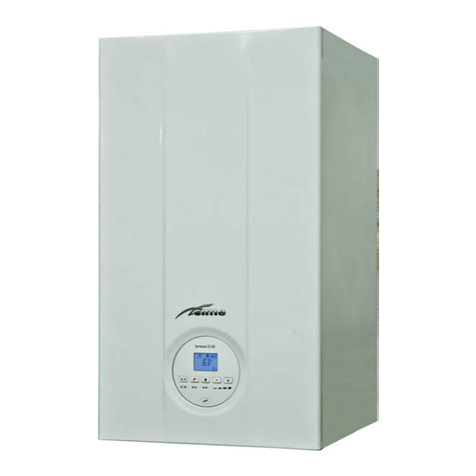
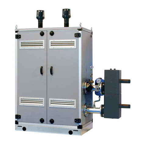
Sime Dewy Equipe P100 Box User guide

Dewy Equipe Box
P100-P600

All descriptions and illustrations provided in this manual have been carefully prepared but we reserve the right to make
changes and improvements in our products that may affect the accuracy of the information contained in this manual.

................................................................................................................................... pag. 4
............................................................................................................................................... pag. 12
...................................................................................................................................................... pag. 20
.............................................................................................................................. pag. 23
IT IS A STATUTORY REQUIREMENT THAT ALL GAS APPLIANCES ARE INSTALLED BY COMPETENT PERSONS,
IN ACCORDANCE WITH THE GAS SAFETY (INSTALLATION AND USE) REGULATIONS (CURRENT EDITION).
The manufacturer’s instructions must not be taken as overriding any statutory requirements, and failure to
comply with these regulations may lead to prosecution.
No modifications to the appliance should be made unless they are fully approved by the manufacturer.
DO NOT OPERATE ANY ELECTRICAL SWITCH, OR USE A NAKED FLAME. TURN OFF THE GAS
SUPPLY AND VENTILATE THE AREA BY OPENING DOORS AND WINDOWS CONTACT THE GAS EMERGENCY
SERVICE ON 0800111999.

DEWY EQUIPE P100 BOX
DEWY EQUIPE P200 BOX
180
790
396
156
567
90
272
307
777
S3
M
R
G
1600
648
307
390
470
1100
640
180
790
396
156
567
90
272
307
777
S3
M
R
G
1600
390
640 630
648
307
2010
2010
4
are
pre-mixed condensation heating modu-
les intended only for heating, inter-con-
nectible and easy to assemble, designed
to work singularly or in sequence/casca-
de automatically.
They are designed and constructed to
meet European directives 92/42/CEE,
2009/142/CEE, 2014/30/UE, 2014/35/UE.
Fig. 1
FIXTURES
M System supply (Flange PN6-DN100)
R System return (Flange PN6-DN100)
G Gas (Flange PN6-DN50)
S3 Condensate drain ø 40

5
DEWY EQUIPE P300 BOX
DEWY EQUIPE P400 BOX
470630 390 18 0
6401730
790
396
15 6
567
90
272
307
777
S3
M
R
G
648
307
1600
180
790
396
15 6
567
90
272
307
777
S3
M
R
G
1600
648
307
6402200
470630 470390
2010
2010
Fig. 1/a
FIXTURES
M System supply (Flange PN6-DN100)
R System return (Flange PN6-DN100)
G Gas (Flange PN6-DN50)
S3 Condensate drain ø 40

6
DEWY EQUIPE P500 BOX
DEWY EQUIPE P600 BOX
180
790
396
15 6
567
90
272
562
1197
S3
M
R
G
1600
180
790
396
15 6
567
90
272
562
1197
S3
M
R
G
1600
1090
1090 2830
3300
307
648
307
648
470630 470630 470 390
390
630
470
630
470
2010
2010
Fig. 1/b
FIXTURES
M System supply (Flange PN6-DN100)
R System return (Flange PN6-DN100)
G Gas (Flange PN6-DN50)
S3 Condensate drain ø 40

7
Nominal heat output (80-60°C) kW 94.9 189.8 284.7 379.6 474.5 569.5
Nominal heat output (50-30°C) kW 103.4 206.8 310.2 413.6 517.1 620.5
Minimum heat output G20 (80-60°C) kW 29.3 29.3 29.3 29.3 29.3 29.3
Minimum heat output G20 (50-30°C) kW 32.1 32.1 32.1 32.1 32.1 32.1
Minimum heat output G31 (80-60°C) kW 29.3 29.3 29.3 29.3 29.3 29.3
Minimum heat output G31 (50-30°C) kW 32.1 32.1 32.1 32.1 32.1 32.1
Nominal heat input kW 96.6 193.2 289.8 386.4 483.0 579.6
Minimum heat input G20 kW 30.0 30.0 30.0 30.0 30.0 30.0
Minimum Minimum heat input G31 kW 30.0 30.0 30.0 30.0 30.0 30.0
Min-max operating yield (80-60°C) % 97.7-98.2 97.7-98.2 97.7-98.2 97.7-98.2 97.7-98.2 97.7-98.2
Min-max operating yield (50-30°C) % 107.0-107.0 107.0-107.0 107.0-107.0 107.0-107.0 107.0-107.0 107.0-107.0
Operating yield at 30% (40-30°C) % 108.0 108.0 108.0 108.0 108.0 108.0
Energy yield markings (CEE 92/42) «««« «««« «««« «««« - -
Heat modules n° 1 1 1 of + 2 of 1 of + 3 of
1 of 2 of
Exhaust temperat. at Q. Nominal (80-60°C) °C 64 64 64 64 64 64
Exhaust temperat. at Q. Minimum (80-60°C) °C 51 51 51 51 51 51
Exhaust temperat. at Q. Nominal (50-30°C) °C 45 45 45 45 45 45
Exhaust temperat. at Q. Minimum 50-30°C) °C 40 40 40 40 40 40
Minimum/Maximum exhaust capacity g/s 15/46 15/92 15/138 15/184 15/230 15/276
CO2 at Q. Nominal/Minimum G20 % 9.0/9.0 9.0/9.0 9.0/9.0 9.0/9.0 9.0/9.0 9.0/9.0
CO2 at Q. Nominal/Minimum G31 % 10.0/10.0 10.0/10.0 10.0/10.0 10.0/10.0 10.0/10.0 10.0/10.0
Feeding tensionV-Hz 230-50 230-50 230-50 230-50 230-50 230-50
Electrical power absorbed W 330 660 990 1320 1650 1980
Absorbed power IPX4D IPX4D IPX4D IPX4D IPX4D IPX4D
CE certification n° 1312BP4142 1312BP4142 1312BP4142 1312BP4142 1312BP4142 1312BP4142
Category II2H3P II2H3P II2H3P II2H3P II2H3P II2H3P
Type B23-53/B23P-53P B23-53/B23P-53P B23-53/B23P-53P B23-53/B23P-53P B23-53/B23P-53P B23-53/B23P-53P
NOx class 5 5 5 5 5 5
Max operating pressure bar 5 5 5 5 5 5
Max operating temperature °C 85 85 85 85 85 85
Water content modules l 19.6 36.3 55.9 72.6 92.2 108.9
Single module temperature regulation °C 20/80 20/80 20/80 20/80 20/80 20/80
Supply pressure G20/G25 mbar 20/25 20/25 20/25 20/25 20/25 20/25
Supply pressure G31 mbar 37 37 37 37 37 37
Number of nozzles n° 1 2 3 4 5 6
Nozzle diameter G20/G25 ø 11.0 11.0 11.0 11.0 11.0 11.0
Nozzle diameter G31 ø 8.4 8.4 8.4 8.4 8.4 8.4
Consumption at nom./min. power G20 m3/h 10.22 20.44 30.67 40.89 51.11 61.33
Consumption at nom./min. power G31 kg/h 7.50 15.01 22.51 30.02 37.52 45.03
kg 240 390 620 770 1000 1150

8

9

1
26
25
22
5
6
27 18
17
24
15
16
10
11
9
814
13
M
R
G
S3
23
12
28
Fig. 2
KEY
1 Hydraulic separator (optional)
5 Condensate trap
6 Gas valve
8 Fan
9 Heating probe (SM)
10 Safety thermostat 95°C
11 Exhaust thermostat
12 Primary exchanger
13 Diaphragm
14 Differential pressure switch
15 Water pressure transducer
16 Air escape valve
17 Non return valve
18 Distributor
22 3-way drain valve
23 System supply valve
24 Manual drain vent
25 Gas tap
26 8 litre expansion tank (optional)
27 5 BAR safety valve
28 Condensate trap frost sensor
FIXTURES
M System flow
R System return
G Gas
S3 Condensate drain
10

11
1
2
3
4
5
6
7
8
9
10
11
13
24
14
15
16
19
20
21
22
23
Fig. 3
KEY
1 System return manifold
2 Gas manifold
3 Gas isolation valve
4 System supply manifold
5 Gas isolation valve
6 Fan
7 Ignition electrode
8 Ionisation electrode
9 Ignition transformer
10 Exhaust thermostat
11 Control panel
13 Air pressure switch
14 Heating probe (SM)
15 Safety thermostat 95°C
16 Differential pressure switch
19 Pump
20 5 BAR safety valve
21 Manual drain
22 Flow isolation valve
23 3-way isolation valve
24 Shunt box

12
The boiler must be installed in a fixed
location and only by specialized and quali-
fied person in compliance with all instruc-
tions contained in this manual. The instal-
lation of this boiler must be in accordance
with the relevant requirements of the
current Gas Safety (installation and use),
the local building regulations, and and
I.E.E. wiring regulations.
Detailled recommendations for air sup-
ply are given in BS5440:2. The following
notes are for general guidance:
– It is not necessary to have a pur-
pose provided air vent in the room or
compartment in which the appliance
is installed. However, suitable clear-
ances for maintenance and servicing
should be provided, see fig. 1.
.
BS6644:2005 has a requirement that the
temperatures in a room or compartment
do not exceed certain levels:
– 25°C at floor level (0-100 mm)
– 32°C at mid level (1.5 M above the floor
level)
– 40°C at ceiling level (0-100 mm from
ceiling)
The following is provide for your guidan-
ce only, and assumes the ventilation air
is taken directly from outside. The sizes
of the vents may need to be increased in
respect of other appliances installed in
the same area, and seasonal use. Take
care that the position of low level vents
would not subject to adverse weather
conditions, ie flooding.
Installed in a room
High level (within 15% of the room height
from ceiling) - 2 cm2/KW of net heat
input
Low level (low as possible within 1 metre
from floor natural gas, 250 mm LPG)– 4
cm2/KW of net heat input. Therefore a
single 60 BFR (58 KW net input) boiler
would require 116 cm2 at high level and
232 cm2 at low level. A single 100 BFR
(98 KW net input) boiler would require
196 cm2 at high level and 392 cm2 at low
level.
Installed in a compartment or enclosure
High level (within 15% of the room height
from ceiling) - 5 cm2/KW of net heat
input.
Low level (low as possible within 1 metre
from floor natural gas, 250 mm LPG) – 10
cm2/KW of net heat input.
Therefore a single 60 BFR (58 KW net
input) boiler would require 290 cm2 at
high level and 580 cm2 at low level.
A single 100 BFR (98 KW net input) boiler
would require 490 cm2 at high level and
980 cm2 at low level.
Installed in a room
High level (within 15% of the room height
from ceiling) - 2 cm2/KW of net heat
input
Low level (low as possible within 1 metre
from floor natural gas, 250 mm LPG)– 2
cm2/KW of net heat input
Therefore a single 60 BFR (58 KW net
input) boiler would require 116 cm2 at
high level and 116 cm2 at low level.
A single 100 BFR (98 KW net input) boiler
would require 196 cm2 at high level and
196 cm2 at low level.
Installed in a compartment or enclosure
High level (within 15% of the room height
from ceiling) - 5 cm2/KW of net heat
input
Low level (low as possible within 1 metre
from floor natural gas, 250 mm LPG)– 5
cm2/KW of net heat input.
Therefore a single 60 BFR (58 KW net
input) boiler would require 290 cm2 at
high level and 290 cm2 at low level.
A single 100 BFR (98 KW net input) boiler
would require 490 cm2 at high level and
490 cm2 at low level.
and
heat modules, inter-connectible by flan-
ge, are supplied with an external pre-
painted zinc-coated laminate case.
Available separately:
– Double box (size: 1100 x 790 x 1600) for
hydraulic separator code 8101527 (fig.
4)
– Hydraulic separator kit code 8101552
for modules
and code 8101553 for modules
– Sequence/cascade control unit code
8096301 supplied for
and code 8096308
supplied for
–
Polypropylene exhaust manifold kit for
indoor installation (purposely treated to
resist weathering when installed outdo-
ors):
code 8102510 for module
code 8102530 for module
code 8102531 for module
code 8102532 for module
code 8102533 for module
code 8102534 for module
– Exhaust terminal code 8089530 for
outdoor installations.
1600
470
308
11 00 790
396 396
635
562
Fig. 4

Before connecting the boiler it is recom-
mended that the system be flushed in
accordance to BS 7593, to eliminate any
foreign bodies that may be detrimental to
the operating efficiency of the appliance.
When connecting up the boiler the clear-
ances in fig 1 should be respected.
The boiler is supplied with a valve pack
part number 5184817.
The gas connection must be made using
seamless steel or copper.
Where the piping has to pass through
walls, a suitable insulating sleeve must
be provided. When sizing gas piping,
from the meter to the boiler, take into
account both the volume flow rates (con-
sumption) in m3/h and the relative den-
sity of the gas in question.
The sections of the piping making up
the system must be such as to guaran-
tee a supply of gas sufficient to cover
the maximum output available, limiting
pressure loss between the gas meter
and any apparatus being used to not
greater than 1.0 mbar for family II gases
(natural gas). An adhesive data badge is
sited inside the front panel; it contains all
the technical data identifying the boiler
and the type of gas for which the boiler
is arranged.
To ensure safe disposal of the conden-
sate produced by the flue gases, refer-
ence should be made to BS6798:2000.
The boiler incorporates a condensate
trap which has a seal of 75 mm, there-
fore no additional trap is required. The
condensate should ideally be discharged
internally into an internal waste pipe
(washing machine/sink waste) or a soil
pipe to avoid the risk of freezing. External
pipe runs should be avoided, but if it is
necessary, the pipework should be at
least 32 mm and protected from the risk
of freezing with a waterproof insulation
and the length kept to a minimum and
not exceeding 3 m. termination should be
into an external gully or purpose made
soakaway.
The exhaust terminal for single module
cod. 8089530 is required for this type
of installation. For separately supplied
accessory assembly see fig. 5.
Refer to fig. 5/a-5/b-5/c for this type of
installation.
The indicated solutions have the exhaust
13
Fig. 5
STAFFA TELAIO
CALDAIA
GMR
Pmin
Pmax
400
DEWY EQUIPE P200 BOX - Right side exhaust manifold kit
ø 160
521
DEWY EQUIPE P200 BOX - Left side exhaust manifold kit
Fig. 5/a

14
400
H
ø 200
DEWY EQUIPE P300-P400 BOX - Right side exhaust manifold kit
DEWY EQUIPE P300-P400 BOX - Left side exhaust manifold kit
Fig. 5/b

15
DEWY EQUIPE P500-P600 BOX - Right side exhaust manifold kit
DEWY EQUIPE P500-P600 BOX - Left side exhaust manifold kit
ø 250
H
Fig. 5/c

manifold positioned both on the module’s
right and left and the use of extensions,
supplied separately.
The kit code 8101532 supplied as option
for
,
can be installed both with con-
nections on left or right side
and is made
up of the following components (fig. 6):
– System supply/return flanged section
code 6291968
–
Expansion vessel 8 liters code 6245108,
connection pipe code 6227661, gaskets
and nipple.
The kit code 8101533 supplied as option for
,can be
installed both with connections on left or
right side and is made up of the following
components models it is formed (fig. 6/a):
– System supply/return flanged section
code 6291971
–
Expansion vessel 8 liters code 6245108,
connection pipe code 6227661, gaskets
and nipple.
16
Fig. 6/a
Fig. 6
BOILER 1 BOILER 2 BOILER 3 BOILER 4
DEWY EQUIPE P200 DEWY EQUIPE P300 DEWY EQUIPE P400
DEWY EQUIPE P500
DEWY EQUIPE P600
BOILER 1 BOILER 2 BOILER 3 BOILER 1 BOILER 2 BOILER 3
KEY
L Live
N Neutral
C RVA 47 regulator
R1 536 Ohm resistance (1)
R2 562 Ohm resistance (1)
R3 604 Ohm resistance (1)
R4 649 Ohm resistance (1)
(1) Resistances are supplied in RVA
47 sequence/cascade kit code
8096301/08.
Fig. 6/b

17
The head available of the generator sup-
ply/return manifolds vs. the flow rate is
shown on the chart of fig. 7.
Hydraulic separator load losses are indi-
cated in the diagram in fig. 7.
400
500
600
700
PORTATA (m3/h)
51015
0
100
200
300
∆p (mbar)
Dewy Equipe /Murelle Equipe
800
20
CAPACITY (m3/h)
100
150
5
PORTATA (m3/h)
10 15 20 25 30
0
50
∆p (mbar)
35 40 45
200
CAPACITY (m3/h)
Fig. 7
BOILER 1 BOILER 2 BOILER 3 BOILER 4
DEWY EQUIPE P200 DEWY EQUIPE P300 DEWY EQUIPE P400
DEWY EQUIPE P500
DEWY EQUIPE P600
BOILER 1 BOILER 2 BOILER 3 BOILER 1 BOILER 2 BOILER 3
KEY
L Live
N Neutral
C RVA 47 regulator
R1 536 Ohm resistance (1)
R2 562 Ohm resistance (1)
R3 604 Ohm resistance (1)
R4 649 Ohm resistance (1)
(1) Resistances are supplied in RVA
47 sequence/cascade kit code
8096301/08.
Fig. 6/c

18
The hydraulic separator is supplied
separately in a kit code 8101552 com-
plete with gaskets, nuts and fastening
screws (fig. 8).
The hydraulic separator is supplied sepa-
rately in a kit code 8101553 complete
with gaskets, nuts and fastening screws
(fig. 9). The plant is supplied with three
supporting “C” brackets that should be
used only to rest the compensator onto
the ground.
Each module is supplied with a power
cord which, if replacement is required,
must be ordered from SIME. 230V – 50 Hz
single phase voltage is required using a
fuse protected main switch with at least
3 mm. between contacts. Observe the L –
N polarity and earthing connection.
Fig. 10
KEY
EV1 Gas valve coil
EV2 Gas valve coil
EA Ignition electrode
ER Ionisation electrode
TS Safety thermostat 100°C
V Fan
TPA Water pressure transducer
PI Pump
SA Condensate trap frost sensor
SM Heating probe
TR 230 – 24V transformer
PD Differential pressure switch
SV Fan board
TF Exhaust thermostat
PA Air pressure switch
TRA Ignition transformer
RSA Resistance 100 (Ω)
R Resistance*
* The resistance in sequence/cascade instal-
lations is supplied in RVA 47 unit kit code
8096301/08. Use the resistance according to
module use (Boiler 1,2,3 or 4).
CONNECTOR SPARE PART CODES:
code 6278613
code 6299971
code 6293595
code 6293594
code 6293593
C
Fig. 8
C
Fig. 9

19
Modules are electrically connected to the terminal
board in the shunt box.
Insert the rubber pipe of the module that has to be con-
nected into the corresponding hole on the box wall.
Fix the rubber pipe to the internal wall of the box using
the straps provided.
Fig. 11
Fig. 11/a
Remove the two upper screws from the shunt
box supplied with the box and adjust the box
cover downwards. Remove the black orifice cap
and insert regulator RVA 47. Connect regulator
RVA 47 to the power supply, as shown in the
layout of Figure 6/b-6/c. After completing the
connection, close the box cover.

20
Built according to Low Voltage direc-
tive CEE 2006/95 and powered at 230
Volt, via a transformer it sends 24 Volt
power to the following components: gas
valve, safety thermostat, heating probe,
water pressure transducer and air pres-
sure switch. An automatic and continual
modulation system permits the boiler to
adjust power to the various system or
user needs. Electronic components are
guaranteed to operate in a temperature
range from 0 to +60°C.
Errors or malfunctions are indicated by
flashing LEDs as shown in fig. 12.
The electronic board is equipped with the
following devices:
– (10 fig. 13)
Adjusts maximum heating power.
To increase the value, rotate the trim-
mer clockwise, to reduce it, rotate the
trimmer counter-clockwise.
– (6 fig. 13)
Trimmer to vary the gas valve ignition
pressure level (STEP). According to
the type of gas the boiler is designed
for, the trimmer must be adjusted to
achieve a burner pressure of appro-
ximately 6.5 mm H2O for methane
gas and 9.5 mm H2O for propane gas
(G31).
To increase pressure, rotate the trim-
mer clockwise, to reduce it, rotate
the trimmer counter-clockwise. The
slow ignition pressure level can be set
during the first five seconds after the
burner is lit.
– (5 fig. 13)
The electronic board is programmed,
during heating, with a technical bur-
ner delay of about 90 seconds that
is performed both at cold start and
subsequent ignitions.
This is to prevent rapid ignitions and
shutdowns that could, in particular,
occur in systems with high load los-
ses. Each time the boiler restarts,
after the slow ignition, for about 1
minute it will run at minimum modu-
lation pressure before moving to the
set heating pressure. The addition of
a bridge will cancel both the program-
med technical delay and the minimum
pressure operating period at ignition.
In this case, the time between shut-
down and the next ignition will depend
on a 5°C differential detected by the
heating probe (SM).
– (13 fig. 13)
For correct module operations, the dip
switches must be positioned as indica-
ted below:
– (14 fig. 13)
The bridge must always be .
– (15 fig. 13)
This will normally be off.
It is only engaged in sequence/casca-
de installations with several boilers.
No communication with
“Logical Remote Control”
blinking red led
Green led off without
power supply
Blinking red air pressure switch fault led
Insufficient water pressure
blinking red led (*)
Heating probe fault blinking red led (SM)
System safety valve triggered
blinking red led (*)
Red ignition lock led:
turn the CR/OFF/INV/RELEASE
selector to the release
( ) position
to restore operations
Safety/exhaust thermostat triggered blinking
red led. Turn the CR/OFF/INV/RELEASE
selector to the release ( ) position
to restore operations
(*) If all leds are off, check water pressure transducer connec-
tions.
Fig. 12
Flame detection circuit fault blinking red led
Blinking red fan fault led. 30 minutes after the fan turns off, the board attempts
to restart it. To identify where the fault occurred in sequence/cascade installations,
turn the CR/OFF/INV/RELEASE selector on each module to the ( ) position
and check where the red fault led blinks.
Other manuals for Dewy Equipe P100 Box
2
This manual suits for next models
5
Table of contents
Other Sime Heater manuals
Popular Heater manuals by other brands

Brant Radiant Heaters
Brant Radiant Heaters DX2-20-60 user manual
Myson
Myson Rio Operating installation and instructions
Oceanic
Oceanic OCEACV100IFW2 instructions
PVG
PVG SRE 10x C operating manual
Schwank
Schwank ecoSchwank-X 6 - IL-X 25 Installation & owner's manual
VTS Medical Systems
VTS Medical Systems WING W Series Technical documentation
