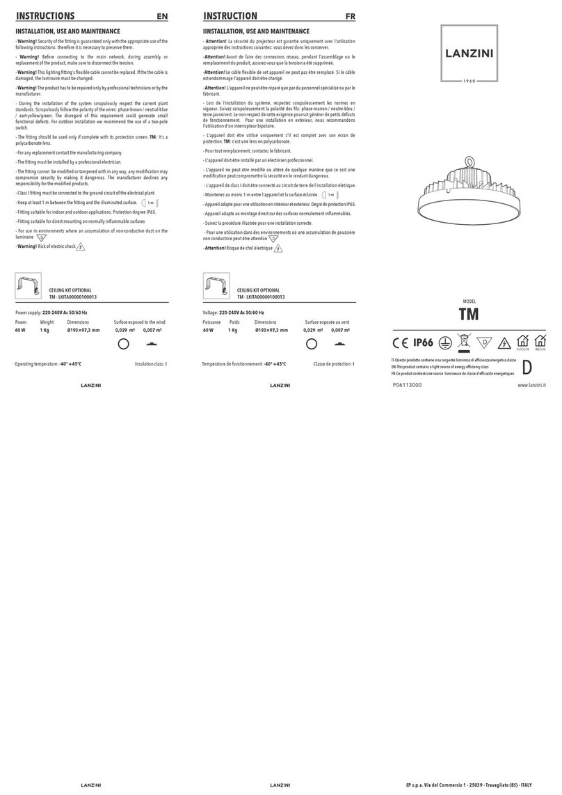
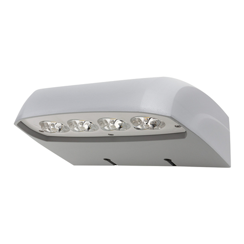
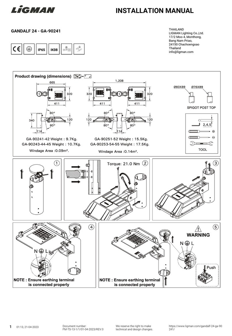
SIMES S.3430 Installation guide

MICROLED 350mA DA COLLEGARE IN SERIE
MICROLED CALPESTABILE PIATTO: - Artt. S.3430 - S.3431 - S.3432 - S.3433 - S.3434 1 TOPLED
MICROLED CALPESTABILE BOMBAT
O
- Artt. S.3410 - S.3411 - S.3412 - S.3413 - S.3414 1 TOPLED
MICROSPARKS A 1 FINESTRA: - Artt. S.3480 - S.3481 - S.3482 - S.3483 - S.3484 1 SIDELED
MICROSPARKS A 2 FINESTRE: - Artt. S.3470 - S.3471 - S.3472 - S.3473 - S.3474 1 SIDELED
MICROSPARKS A 12 FINESTRE: - Artt. S.3450 - S.3451 - S.3452 - S.3453 - S.3454 1 SIDELED
CARATTERISTICHE TECNICHE
Corpo in alluminio pressofuso; anello in acciaio inox (per calpestabile) - calotta in alluminio pressofuso (per microsparks)
Diffusore e guscio in policarbonato saldati ad ultrasuoni. Viti in acciaio inox A4. Fornito cablato con 1 metro di cavo
Verniciatura a polveri con alta resistenza alla corrosione con pretrattamento di fosfocromatazione
CLASSE III IP 67 parte frontale - IP20 parte retrostante dell'incasso
Funzionamento con corrente continua 350 Ma.
ISTRUZIONI DI MONTAGGI
O
PER APPLICAZIONE CON CASSAFORM
A
:installare la cassaforma nel pavimento o terreno lasciandovi sporgere
circa 15cm di cavo e avendo cura di lasciare sul fondo 20 cm di ghiaia di drenaggio.
Effettuare il cablaggio tra il cavo di alimentazione e il cavo fornito con l'apparecchio
Inserire l'apparecchio nella cassaforma preinstallata e fissarlo con le 2 viti in dotazione
PER APPLICAZIONE TIPO CONTROSOFFITTO:preparare nel controsoffitto, che deve avere spessore fra 5mm e 15mm, un
foro, Dmin=57mm e Dmax=59mm; effettuare il cablaggio tra il cavo di alimentazione e il cavo fornito con l'apparecchio.
Montare le staffette con le viti M3X40 e inserire l'apparecchio nel foro della controsoffittatura avvitare le 2 viti M3X40.
Fissare l'apparecchio andando ad avvitare le 2 viti M3X40.
N.B.: Lasciare almeno 50mm di aria libera tra l'intorno dell'apparecchio e le pareti dell'incasso.
L'apparecchio non deve, in nessuna circostanza, essere ricoperto con materiale isolante o similare
Gli assorbimenti sono pari a: 1,4W per LED BLU - BIANCO - VERDE
0,8W per LED ROSSO O GIALLO
ISTRUZIONI DI CABLAGGI
O
Il cablaggio deve essere effettuato collegando il cavo di alimentazione ( 350mA ) al cavo fornito con l'apparecchio
e deve essere eseguito in modo da garantire il grado di tenuta originale dell'apparecchio.
Per il cablaggio utilizzare morsetti di alimentazione bipolari certificati con morsetti a vite, 24V - 2x2,5 mm
2
- T 85°C
Esso deve essere effettuato nel vano cassaforma o in una scatola di derivazione (non fornita)
Rispettare la polarità di alimentazione del circuito LED, invertendola il circuito non funziona.
La connessione di più prodotti allo stesso alimentatore deve essere eseguita con CABLAGGIO IN SERIE
NOTE: Nel caso di danneggiamento del cavo fornito il prodotto non è più utilizzabile
Per l'installazione utilizzare le apposite cassaforme. L'apparecchio è installabile anche a parete e a soffitto
Togliere tensione prima di effettuare manutenzioni
Usare cavi di alimentazione di tipo HAR
Utilizzare alimentatori conformi alle norme EN 61347-2-2; ad esempio art. S.3405 SIMES
La distanza tra alimentatore e a
pp
arecchi deve essere al massimo di 15 metri
Assicurarsi che la corrente fornita al
p
rodotto non su
p
eri i 350 Ma
L'apparecchio è idoneo al montaggio su superfici normalmente infiammabili
Apparecchio approvato per servizio gravoso
L' installazione deve essere eseguita da personale qualificato secondo le norme di settor
e
Il rispetto di queste norme è molto importante per l'efficienza dell'apparecchio
e per la sicurezza delle persone, pertanto esse vanno conservat
e
ISTRMICROLED1W REV.1 - 04/05
OK NO
65mm
65mm
7mm
110mm
60mm
65mm
14mm
65mm
110mm
60mm
65mm
65mm
2mm
110mm
60mm
110mm
60mm
65
mm
2
6
mm
2
5
mm

MICROLED 350mA TO BE WIRED IN SERIE SYSTEM
RECESS BOX
MICROLED WALK OVER FLAT: - Artt. S.3430 - S.3431 - S.3432 - S.3433 - S.3434 1 TOPLED
MICROLED WALK OVER BOWL: - Artt. S.3410 - S.3411 - S.3412 - S.3413 - S.3414 1 TOPLED
MICROSPARKS WITH 1 WINDOW: - Artt. S.3480 - S.3481 - S.3482 - S.3483 - S.3484 1 SIDELED
MICROSPARKS WITH 2 WINDOWS: - Artt. S.3470 - S.3471 - S.3472 - S.3473 - S.3474 1 SIDELED
MICROSPARKS WITH 12 WINDOWS: - Artt. S.3450 - S.3451 - S.3452 - S.3453 - S.3454 1 SIDELED
TECHNICAL CHARACTERISTICS:
Body in die casting aluminium, ring in stainless steel (for walk over) and cover in die cast aluminium (for microsparks)
Diffuser and inferior shell in polycarbonate welded with ultrasound. A4 stainless steel screws. Supplied with 1 meter of cable
Podwer paint with high corrosion resistance with pre-phosphocromatation treatment
CLASS III PROTECTION LEVEL : IP 67
Working Current : 350mA DC
ASSEMBLING INSTRUCTIONS:
WITH RECESS BOX: Fix the recess box in the concrete or in the ground, with 15cm of supply cable for maintenance and
wire the power supply cable with the supplied cable
Insert the fitting in the pre-installed recess box and fix it with the 2 screws supplied
CEILING APPLICATION: prepare an adeguate hole in the ceiling, Dmin=57mm Dmax=59m
m
, (the thikness of the ceiling
must be between 5mm and 15mm); wire the power supply cable with the supplied cable
NOTES: Leave at least 50mm of free air between the fitting and the surface of the hole for the recess
The fitting must never be covered by insulating material, in every case.
Mount the clip with the 2 M3X40 screws. Insert the fitting in the hole and fix it screwing the 2 M3X40 screws
The power absorbed of the fitting are: 1,4W for BLUE - WHITE-GREEN LED
0,8W for RED - YELLOW LED
WIRING INSTRUCTIONS:
Connect the cable wires (350mA) with the supplied cable in order to garantee the IP67
The wiring must be do with bipolar terminal block with screws in according with the norms 24V - 2x2,5 mm2- T 85°C
The wiring must be done in the recess box or in a connecting box (not supplied
)
Respect the polarity of LED circuit ; if the wires are reversed the circuit doesn't work.
Connection of more then one product to the same power supply require a SERIES CONNECTIO
N
REMARKS: In case of damage of the supplied cable the fitting is not usable.
Use the appropriate recess box for reces
s
Disconnect the fitting before the maintenance
Use HAR supply cable
Is possible the applications wall recessed or down ligh
t
Is important the polarity. Mantain a distance from fitting to the Electronic ballast of max 15 meters
Use ballast in according with the norms EN 61347-2-2; for example art. S.3405 from SIMES
Supply current must not exceed 350 Ma
The fitting is suitable to the mounting on normal inflammable surfaces
Fitting approved for shock up to 6,5 Joule
Installation should be carried out by a suitably qualified person in accordanc
e
with good electrical practice and the appropiate national wiring regulation
s
Is very important to follow these instructions to, enable the fitting to be installed
correctly. Please retain for information. ISTRMICROLED1W REV.1 - 04/05
OK NO
65mm
65mm
7mm
110mm
60mm
65mm
14mm
65mm
110mm
60mm
65mm
65mm
2mm
110mm
60mm
110mm
60mm
65
mm
2
6
mm
2
5
mm

HOW TO MAKE THE ELECTRICAL CONNECTION
COME EFFETTUARE IL CABLAGGIO ELETTRICO
1 - INSIDE THE RECESS BOX WITH CONNECTION IP67
1 - NELLA SCATOLA INCASSO CON COLLEGAMENTO CON GRADO DI IP67
FOLLOWING THE STEPS 1-7
COME INDICATO NELLA SEQUENZA 1-7
2 - INSIDE AN IP67 REMOTE BOX
2 - IN UNA SCATOLA SEPARATA - IP6
7
WITH TERMINAL BLOCK
CON MORSETTI
4-TO RE-MAKE THE ORIGINAL
INSULATIONS OF CABLE
4-PER RIPRISTINARE L'ISOLAMENTO
ORIGINALE
5-FIT THE FITTING TO THE RECESS
BOX
5-FISSARE L'APPARECCHIO ALLA
CASSAFORMA
3- IN A BOX WITH RESIN TO OBTAIN
AN IP67 PROTECTION
3- IN UNA SCATOLA CON RESINA PER
OTTENERE GRADO IP67
2-CONNECT THE WIRES…...
2-COLLEGARE I CAVI…...
1-PREPARE THE WIRES
1-PREPARARE I CAVI
FLOATING FLOORS, FLOATING WALLS OR CEILING APPLICATION
APPLICAZIONE PER PAVIMENTI FLOTTANTI, PANNELLI O SOFFITTI
Mount the CLIP in this position
Montare le CLIP in questa posizione
5-15mm
57-59mm
foro - hole
CLIP
viti M3X40
M3X40 screws CLIP

N°6 pressacavi PG11 per uscite in corrente continua
N°2 pressacavi PG11 per entrata
cavi alimentazione
ALIMENTATORE ELETTRONICO PER SERIE LED A 350mA max 10W art. S.3406
ATTENZIONE: per alimentazione a 220V-240V 50Hz-60Hz ad ogni alimentatore può essere collegato un numero
CARATTERISTICHE TECNICHE
Box in polipropilene
Dimensioni di ingombro 200mm x 200mm x 90mm
Con alimentatore elettronico MAX 10W incorporato, con uscita per led da 350mA
Pressacavi PG11 montati
Gommini in silicone
CLASSE I - IP55
ISTRUZIONI DI MONTAGGIO:
Aprire il box; entrare con cavi di dimensione adeguata (Dmin =7mm Dmax =10,5 mm) ed effettuare il cablaggio elettrico
ATTENZIONE: cablaggio in serie!!
- la rimozione dei ponticelli senza il collegamento dell'apparecchio impedisce il funzionamento del sistema!
- in caso di guasto, anche di un solo apparecchio collegato, il sistema cessa di funzionare!
- r
i
muovere so
l
o
i
pont
i
ce
lli
necessar
i
(
con cavett
i
ner
i)
e co
ll
egare g
li
apparecc
hi
r
i
spettan
d
o
l
e po
l
ar
i
t
à
+
/
-
Bloccare i pressacavi
Dove non sono stati utilizzati i pressacavi PG11 sostituire questi con i gommini in dotazione.
Richiudere il box
Togliere tensione prima effettuare manutenzioni
L' installazione deve essere eseguita da personale qualificato second
o
le norme di settore
Il rispetto di queste norme è molto importante per l'efficienza dell'apparecchio
e per
l
a s
i
curezza
d
e
ll
e persone, per
t
an
t
o esse vanno conserva
te
ISTRS3406 REV.1 04/0
5
BOX IP 55 WITH ELECTRONIC POWER SUPPLY
WIRED FOR SERIES SYSTEM
AVVERTENZE
VERDE - BLU - BIANCO; MAX 6 prodotti di colore ROSSO - GIALLO
ALIMENTATORE ELETTRONICO REMOTO IN BOX IP55
CABLATO PER COLLEGAMENTI IN SERIE
mass
i
mo
di
6
apparecc
hi
Per alimentazione a 110V ad ogni alimentatore può essere collegato max di 4 prodotti di colore
200 mm
200 mm
LN

N°6 cable exit for PG11 cable gland
N°2 cable entry with PG11 cable glands
ELECTRONIC POWER SUPPLY FOR LED RANGE 350mA max 10W art. S.3406
With supply voltage of 220-240V 50-60Hz the max number of luminaire must be of 6.
With supply voltage of 110V 50-60Hz the max number of luminaire must be of 4 for the colour WITHE, BLUE and
GREEN; the max number of luminaire must be of 6 for the colour RED and YELLOW
TECHNICAL INFORMATION:
Box in polypropylene
Dimensions: 200mm x 200mm x 90mm
10W electronic power supply included
Preinstalled PG11 cable gland
Silicone plug
CLASS I - IP55
INSTALLATION INSTRUCTIONS:
Open the box and introduce the cables (Dmin = 7mm Dmax = 10,5 mm) through the cable glands.
Wiring the fitting to the terminal block
Att
en
ti
on: ser
i
es w
i
r
i
ng
!!
- Removing the wiring on the terminal block without the wiring of the fitting the system do not work.
- In case of defect of one fitting the complete system stop to work.
- Remove only the wires (the black wires) on the terminal block necessary and wiring the fitting be carefully to the
polarity + / -
Block the cable glands
Replace the not used cable glands with the supplied silicone plug
s
Close the box
Disconnect the power before maintenance
Installation should be carried out by a suitably qualified person in accordanc
e
with good electrical practice and the appropiate national wiring regulation
s
It is very important to follow these instructions to enable the fitting to be
i
ns
t
a
ll
e
d
correc
tl
y.
Pl
ease re
t
a
i
n
f
or
i
n
f
orma
ti
on. ISTR3406 REV.1 04/0
5
200 mm
200 mm
LN
This manual suits for next models
24
Table of contents
Languages:
Other SIMES Outdoor Light manuals

SIMES
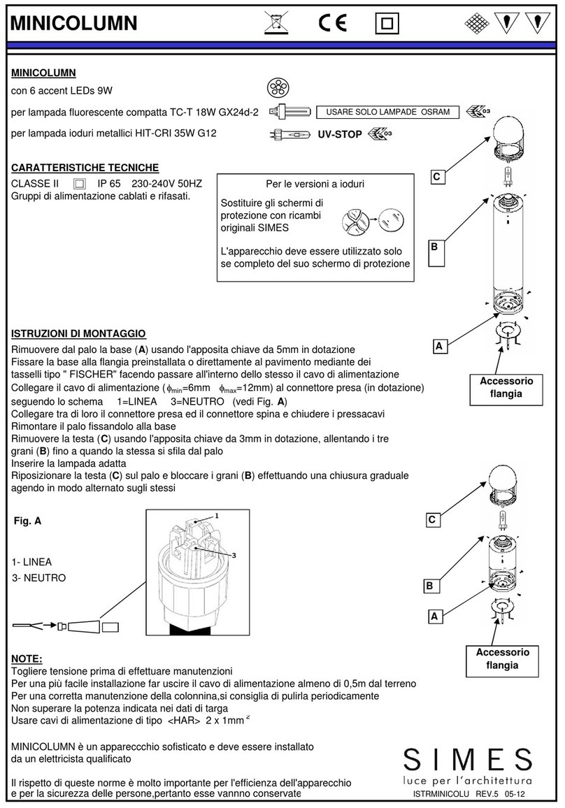
SIMES STELO S.4120W User manual
SIMES
SIMES MINICOLUM User manual
SIMES
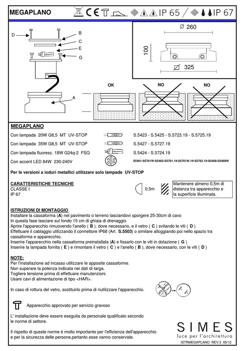
SIMES MEGAPLANO User manual
SIMES
SIMES REEF Series User manual

SIMES
SIMES SLOT VELA S.2836 User manual

SIMES
SIMES MINIBRIQUE STEP RECESSED User manual
SIMES
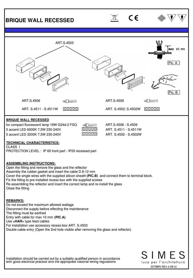
SIMES BRIQUE WALL RECCESSED User manual

SIMES
SIMES MINI MOAI S.6150 User manual

SIMES
SIMES MICROREEF S.5301 Quick start guide

SIMES
SIMES MINISLOT DISK HIT-CRI 70W G12 User manual
