Simex Simpact SLIK-73 User manual

! "#$%
firmware version: 7.03 or higher
Read the user's manual carefully before starting to use the unit.
Producer reserves the right to implement changes without prior notice.
1 .11. 007 V. .00

User manual for universal counter with batching function SLIK-73
CONTENTS
1. BASIC REQUIREMENTS AND USER SAFETY........................................................................................ 3
2. GENERAL CHARACTERISTICS................................................................................................................4
3. TECHNICAL DATA......................................................................................................................................4
4. DEVICE INSTALLATION............................................................................................................................6
4.1. UNPACKING.......................................................................................................................................6
4.2. ASSEMBLY........................................................................................................................................6
4.3. CONNECTION METHOD...................................................................................................................8
4.4. MAINTENANCE................................................................................................................................12
5. FRONT PANEL DESCRIPTION................................................................................................................13
6. PRINCIPLE OF OPERATION...................................................................................................................14
6.1. MEASUREMENT MODE..................................................................................................................14
6.2. BATCHER FUNCTION.....................................................................................................................15
6.3. THE DIGITAL FILTER......................................................................................................................17
6.4. CONTROL OF THE RELAY OUTPUTS..........................................................................................19
7. DEVICE PROGRAMMING.........................................................................................................................21
7.1. PROGRAMMING MENU..................................................................................................................21
7.2. PARAMETERS EDITION.................................................................................................................22
7.2.1. N meric parameters (digit change mode)...............................................................................22
7.2.2. N meric parameters (slide change mode)..............................................................................22
7.2.3. Switch parameters (“LIST” type).............................................................................................23
7.3. MENU DESCRIPTION.....................................................................................................................23
7.3.1. “rELAy” men ..........................................................................................................................24
7.3.2. “Pr inP” parameter...................................................................................................................24
7.3.3. “rESEt” parameter...................................................................................................................25
7.3.4. “ArESEt” parameter.................................................................................................................25
7.3.5. “FiLtEr” parameter...................................................................................................................26
7.3.6. “F nct” parameter....................................................................................................................26
7.3.7. ”PrESCA” men .......................................................................................................................26
7.3.8. ”rS-485” men .........................................................................................................................27
7.3.9. ”SEC ” men ...........................................................................................................................28
7.3.10. ”briGHt” parameter................................................................................................................30
7.3.11. ”Edit” parameter....................................................................................................................30
7.3.12. ”dEFS” parameter..................................................................................................................30
7.4. MENU STRUCTURE........................................................................................................................31
8. E AMPLES OF PRESCALER PARAMETERS CALCULATION............................................................33
9. THE MODBUS PROTOCOL HANDLING.................................................................................................34
9.1. LIST OF REGISTERS......................................................................................................................34
9.2. TRANSMISSION ERRORS DESCRIPTION....................................................................................37
9.3. EXAMPLES OF QUERY/ANSWER FRAMES.................................................................................37
10. DEFAULT AND USER'S SETTINGS LIST.............................................................................................40
2

User manual for universal counter with batching function SLIK-73
Explanation of symbols used in the manual:
- This symbol denotes especially important g idelines concerning the installation and
operation of the device. Not complying with the g idelines denoted by this symbol
may ca se an accident, damage or eq ipment destr ction.
IF THE DEVICE IS NOT USED ACCORDING TO THE MANUAL THE USER IS
RESPONSIBLE FOR POSSIBLE DAMAGES.
- This symbol denotes especially important characteristics of the nit.
Read any information regarding this symbol caref lly
1. BASIC REQUIREMENTS AND USER SAFETY
-&!''
!!!(!!'
'')
- Installation should be conducted by qualified personnel . During installation all
available safety requirements should be considered. The fitter is responsible for
executing the installation according to this manual, local safety and EMC
regulations.
- The unit must be properly set-up, according to the application. Incorrect
configuration can cause defective operation, which can lead to unit damage or
an accident.
- '!*
!!!!''('!''
!')
- &'')&
''''!!!!
+,)
- Neighbouring and mating equipment must meet the requirements of appropriate
standards and regulations concerning safety and be equipped with adequate
anti-overvoltage and anti-interference filters.
--!'(!')&
!)(''
''''!.')
- In order to minimize fire or electric shock hazard, the unit must be protected
against atmospheric precipitation and excessive humidity.
- Do not use the unit in areas threatened with excessive shocks, vibrations, dust,
humidity, corrosive gasses and oils.
- Do not use the unit in explosion hazard areas.
3
!
i
!
!

User manual for universal counter with batching function SLIK-73
- Do not use the unit in areas with significant temperature variations, exposed to
condensation or icing.
- Do not use the unit in areas exposed to direct sunlight.
- Make sure that the ambient temperature (e.g. inside the control box) does not
exceed the recommended values. In such cases forced cooling of the unit must
be considered (e.g. by using a ventilator).
&''!''
'')
2. GENERAL CHARACTERISTICS
Universal programmable counter type "#$% is equipped with many modern features
required in simple and advanced automatic control systems. The counter had been designed
for hard environment conditions, and increased usefulness.
The unit is assembled in panel mounted case with programming keyboard on front panel,
and terminals on back panel. User can use local keyboard to set all necessary parameters due
to his own requirements. Build in RS-485 communication interface enables controlling of all
settings by host, and allows use of unit in advanced network systems.
Two counting inputs (pulse inputs) can operate in few different modes (as two
independent pulse inputs or single quadrature input). Additional programmable input can
change basic function of counting inputs (addition or subtraction of pulses from inputs,
change the direction of counting) or to stop counting without clearing.
Counter type "#$% is equipped with independent clearing input. The device can be
equipped with one relay (or OC type) output with independent threshold, which can be used to
control external devices. The counters "#$%are designed for cooperation with electronic
(PNP and NPN) detectors, and mechanical detectors – switches (build in digital filter allows
connectors denouncing). All inputs are separated from ground of counter, and power supply.
3. TECHNICAL DATA
Power supply voltage
(depending on version)
External fuse (required)
Power consumption
85.../%0... 60V AC/DC; 50 ÷ 60 Hz
or 19.../1...50V DC; 16.../1...35V AC
T - type, max. A
max. 4,5 VA @ 85 ÷ 60V AC/DC
max. 4,5 VA @ 16V ÷ 35V AC
max. 4,5 W @ 19V ÷ 50V DC
Pulse inputs
A and B inputs
C input
D input
COM
counting (terminal no. 6,7)
programmable (terminal no. 8)
reset counter (terminal no. 9)
common terminal (terminal no. 10)
Input levels
low level:
high level:
0V ÷ 1V
10V ÷ 30V
4
!
!

User manual for universal counter with batching function SLIK-73
Max. input frequency
electronic - standard counter: 10 kHz
electronic - quadrature counter: 5 kHz
contact: 90 Hz (adjustable filter)
Display range -99999 ÷ 999999, plus decimal point
Outputs
relay:
or OC-type:
sensor power supply:
1 NO, 1A/ 50V AC (cos ϕ = 1)
1 30mA / 30VDC / 100mW
4V +5%, -10% / max. 100 mA, stabilized
Communication interface RS 485, 8N1 and 8N , Modbus RTU, not separated
Baud rate 1 00 bit/s ÷ 115 00 bit/s
Display LED, 6 digit, 9mm height, red
Data memory non-volatile memory, EEPROM type
Protection level IP 65 (from front, after using waterproof cover)
IP 40 (from front)
IP 0 (housing and connection clips)
Housing type
Housing material
Housing dimensions
Mounting hole
Assembly depth
Panel thickness
panel
NORYL - GFN S E1
7 x 36 x 97 mm
66,5 x 3 ,5 mm
min. 10 mm
max. 5 mm
Operating temperature
Storage temperature
Humidity
Altitude
0°C to +50°C
-10°C to +70°C
5 to 90% no condensation
up to 000 meters above sea level
Screws tightening max. torque 0,5 Nm
Max. connection leads diameter ,5 mm
Safety requirements according to: PN-EN 61010-1
installation category: II
pollution degree:
voltage in relation to ground: 300V AC
insulation resistance: > 0MΩ
insulation strength between power supply and
input/output terminal: 1min. @ 300V
insulation strength between relays terminal: 1min. @
1350V
EMC according to: PN-EN 613 6
& ) '
2)2'
!!!!)
5
!

User manual for universal counter with batching function SLIK-73
4. DEVICE INSTALLATION
The unit has been designed and manufactured in a way assuring a high level of user
safety and resistance to interference occurring in a typical industrial environment. In order to
take full advantage of these characteristics installation of the unit must be conducted correctly
and according to the local regulations.
- Read the basic safety requirements on page 3 prior to starting the installation.
- Ensure that the power supply network voltage corresponds to the nominal
voltage stated on the unit’s identification label.
- The load must correspond to the requirements listed in the technical data.
- All installation works must be conducted with a disconnected power supply.
- Protecting the power supply clamps against unauthorized persons must be
taken into consideration.
4.1. UNPACKING
After removing the unit from the protective packaging, check for transportation damage. Any
transportation damage must be immediately reported to the carrier. Also, write down the unit
serial number on the housing and report the damage to the manufacturer.
Attached with the unit please find:
- user’s manual,
- warranty,
- assembly brackets - pieces.
4.2. ASSEMBLY
- The unit is designed for mounting indoor inside housings (control panel,
switchboard) assuring appropriate protection against electric impulse waves.
Metal housing must be connected to the grounding in a way complying with the
governing regulations.
- Disconnect the power supply prior to starting assembly.
- Check the correctness of the performed connections prior to switching the unit on.
In order to assembly the unit, a 66,5 x 3 ,5 mm mounting hole (Figure 4.1) must be
prepared. The thickness of the material of which the panel is made must not exceed
5mm. When preparing the mounting hole take the grooves for catches located on
both sides of the housing into consideration (Figure 4.1). Place the unit in the
mounting hole inserting it from the front side of the panel, and then fix it using the
brackets (Figure 4. ). The minimum distances between assembly holes’ axes - due
to the thermal and mechanical conditions of operation - are 91 mm x 57mm
(Figure 4.3).
6
!
!
!

User manual for universal counter with batching function SLIK-73
Fig re 4.1. Mo nting hole dimensions
Fig re 4.2. Installing of brackets, and dimensions of connectors.
Fig re 4.3. Minim m distances when assembly of a n mber of nits
7
5 mm
9 mm
1 mm
10 mm
16 mm
8,5 mm
91 mm
57 mm
1 mm max. 5 mm
66,5 mm
3 ,5 mm
1 mm
8 mm
8 mm
8 mm
8 mm

User manual for universal counter with batching function SLIK-73
4.3. CONNECTION METHOD
Caution
- Installation should be conducted by qualified personnel . During installation all
available safety requirements should be considered. The fitter is responsible for
executing the installation according to this manual, local safety and EMC
regulations.
- The unit is not equipped with an internal fuse or power supply circuit breaker.
Because of this an external time-delay cut-out fuse with minimal possible nominal
current value must be used (recommended bipolar, max. A) and a power supply
circuit-breaker located near the unit. In the case of using a monopolar fuse it must
be mounted on the phase cable (L).
- The power supply network cable diameter must be selected in such a way that in
the case of a short circuit of the cable from the side of the unit the cable shall be
protected against destruction with an electrical installation fuse.
- Wiring must meet appropriate standards and local regulations and laws.
- In order to secure against accidental short circuit the connection cables must be
terminated with appropriate insulated cable tips.
- Tighten the clamping screws. The recommended tightening torque is 0.5 Nm.
Loose screws can cause fire or defective operation. Over tightening can lead to
damaging the connections inside the units and breaking the thread.
- In the case of the unit being fitted with separable clamps they should be inserted
into appropriate connectors in the unit, even if they are not used for any
connections.
#'!+*')),'
+))',('
2!*)
- If the unit is equipped with housing, covers and sealing packing, protecting
against water intrusion, pay special attention to their correct tightening or clamping.
In the case of any doubt consider using additional preventive measures (covers,
roofing, seals, etc.). Carelessly executed assembly can increase the risk of electric
shock.
- After the installation is completed do not touch the unit’s connections when it is
switched on, because it carries the risk of electrical shock.
-!'!!!
!!!') &'!!
'*!'')
–Avoid common (parallel) leading of signal cables and transmission cables together with
power supply cables and cables controlling induction loads (e.g. contactors). Such cables
should cross at a right angle.
–Contactor coils and induction loads should be equipped with anti-interference protection
systems, e.g. RC-type.
!

User manual for universal counter with batching function SLIK-73
–Use of screened signal cables is recommended. Signal cable screens should be
connected to the earthing only at one of the ends of the screened cable.
–In the case of magnetically induced interference the use of twisted couples of signal
cables (so-called “spirals”) is recommended. The spiral (best if shielded) must be used
with RS-485 serial transmission connections.
–In the case of interference from the power supply side the use of appropriate anti-
interference filters is recommended. Bear in mind that the connection between the filter
and the unit should be as short as possible and the metal housing of the filter must be
connected to the earthing with largest possible surface. The cables connected to the filter
output must not run in parallel with cables with interference (e.g. circuits controlling relays
or contactors).
Connections of power supply voltage and measurement signals are executed using the
screw connections on the back of the unit’s housing.
Fig re 4.4. Method of cable ins lation replacing and cable terminals
Fig re 4.5. Terminals description (relay o tp t)
Description of control signals' symbols.
34,354 - counting input, pulse;
364 - programmable input;
3-4 - reset counter input;
3674 - common terminal
9
max. mm
6-7 mm
8 /
809 $ : ;
8: 8; /0
8
% 1
8$89
<- -&=
-&#
#1:>
=#
=/1? +5%, -10%
Imax = 100mA
@
!!
(depending on version)
-67
5 6

User manual for universal counter with batching function SLIK-73
Fig re 4.6. Terminals description (OC-type o tp t)
'!!!''A
Depending on version:
85...230...260V AC/DC or
19...24...50V DC; 16...24...35V AC
Fig re 4.7. Connection of power s pply and relay
6!2!!'!*!!)B
!''+((!
( ( ), 2' ''
!! +!!1$CD)/>0?6
800D>B,('!+,'
')2!!(
''('
)
10
!
C
8 /
% 1
C
8
8 /
809 $ : ;
8: 8; /0
% 1
8$89
<- -&=
-&#
#1:>
=#
=/1? +5%, -10%
Imax = 100mA
768
Umax = 30V DC
Imax = 30mA
Pmax = 100mW
#=
768
@
!!
(depending on version)
-67
5 6
!

User manual for universal counter with batching function SLIK-73
a) b)
Fig re 4.8. Examples of s ppression circ it connection:
a) to relay terminals; b) to the ind ctive load
Fig re 4.9. Example of OC-type o tp ts connection
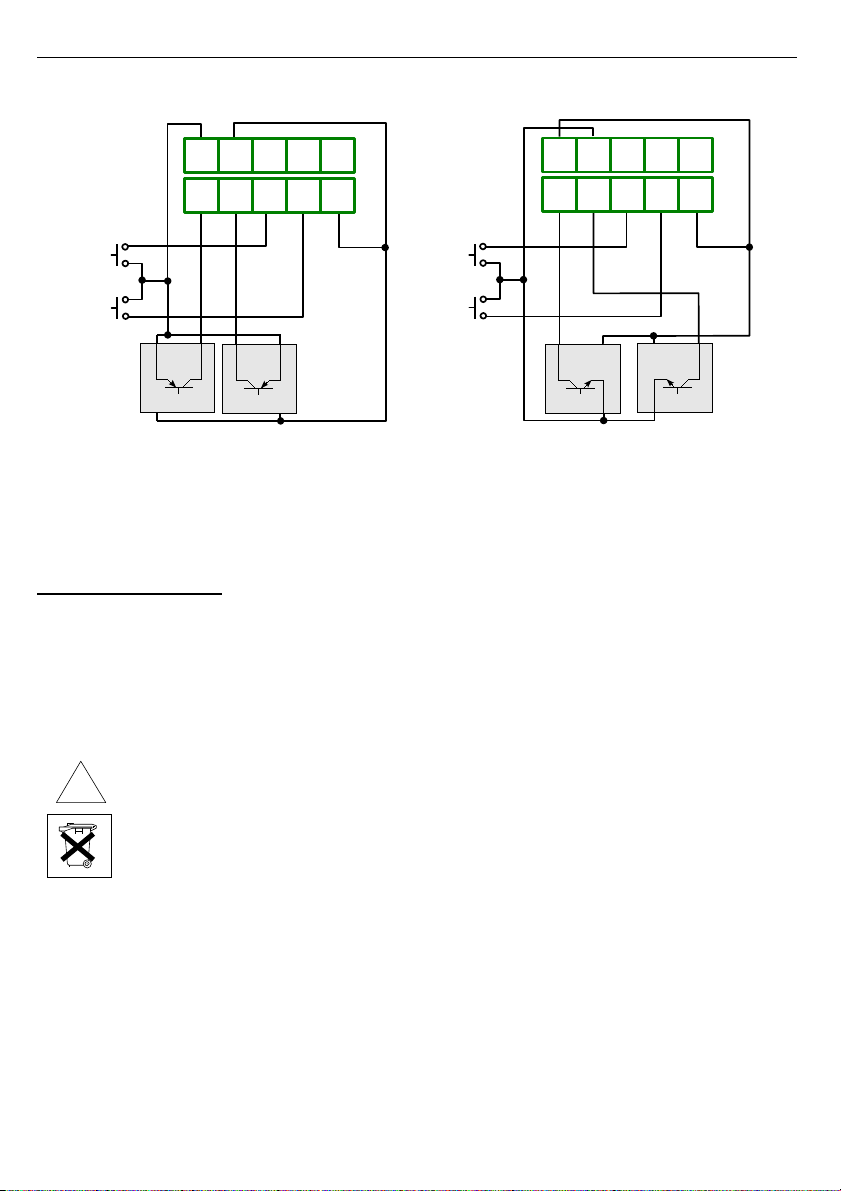
Construction of counter's inputs allows connecting of pulser with common earth (Figure 4.10
a) or common plus (Figure 4.10 b), without additional intermediary circuits (sensor with NPN
or PNP type output); for outputs of push-pull type kind of connection it has no matter.
11
89 8$
% 1
768
#= =#
+
voltage input
4 V
-
Logic controller
89 8$
% 1
768
#=
=#
/*/
-80
!
% 1 % 1
!
User manual for universal counter with batching function SLIK-73
a) b)
Fig re 4.10. An example of p lser connection:
a) with common earth, b) with common pl s.
4.4. MAINTENANCE
The unit does not have any internal replaceable or adjustable components available to
the user. Pay attention to the ambient temperature in the room where the unit is operating.
Excessively high temperatures cause faster ageing of the internal components and shorten the
fault-free time of unit operation.
In cases where the unit gets dirty do not clean with solvents. For cleaning use warm water with
small amount of detergent or in the case of more significant contamination ethyl or isopropyl
alcohol.
Using any other agents can cause permanent damage to the housing.
Product marked with this symbol should not be placed in municipal waste. Please
check local regulations for disposal and electronic products.
12
!
89 8$ 8: 8; /0
9 $ : ; 80
=#
-
67
5
+
+
- -
Pulsers
&
&7@ 6
89 8$ 8: 8; /0
9 $ : ; 80
-67
5
++
--
Pulsers
#=
6
&
&7@

User manual for universal counter with batching function SLIK-73
5. FRONT PANEL DESCRIPTION
Symbols and functions of push-buttons:
Symbol used in the manual:E6DF
Functions:
• Enter to main menu ( press and hold by at least sec.)
• Exit the current level and Enter to previous menu (or measure mode)
• Cancel the changes made in parameter being edited
Symbol used in the manual:E&F
Functions
• Start to edit the parameter
• Enter to the sub-menu,
• Confirmation of changes made in parameter being edited
Symbol used in the manual:EGF
Functions
• Change of the present menu,
• Modification of the parameter value,
• Monitoring of current thresholds and offset,
Symbol used in the manual:EF
Functions
• Change of the present menu,
• Modification of the parameter value,
Symbol used in the manual:E&F
Functions:
• zeroing the counter (see: „rESEt” option, page: 5), the reset must be
confirmed by E&Fbutton.
13
6
&
&
6 &
8
/
C
&
display
Inactive LEDs (R2,F)
Threshold exceeding LED
indicator (R1)
programming p shb ttons

User manual for universal counter with batching function SLIK-73
6. PRINCIPLE OF OPERATION
After turning the power supply on, device ID and software version are showed on the
display, next the data '!!! are restored and device goes to the
selected operation mode.
6.1. MEASUREMENT MODE
In the counting mode (normal mode), the device counts pulses “delivered” to counting
inputs A and B (Figure 6.1) depends on selected function. There are available four functions:
addition of pulses from A and B inputs (“C”=”H”), subtraction of pulses from A and B
inputs (“C” = ”##”), quadrature counting with standard resolution (“C” =”2'#8”) ,
quadrature counting with increased resolution (“C” =”2'#1”).
a)
b)
Fig re 6.1. The co nting principle of the SLIK co nters
(parameters: muL=”1”, div=”1”, oFFSEt=”0”):
a) modes ”A+B”, ”A-B”; b) modes ”quAd-4”, ”quAd-1”
14
A input
B input
A + B
A - B
0 1 3 4 5 7 9 10 11
0 1 1 1 1 1 0 -1
Display result
for mode:
A input
B input
quAd-4
quAd-1
0 1 3 4 5 6 7 8 9 10 11 10 9 8 7 6 5 4 3
0 1 3 1
Display result
for mode:

User manual for universal counter with batching function SLIK-73
Counter recalculates result using three parameters - , 'and( and shows it on the
display. If the result is out of permissible counter range (from“-99999” to “999999”), special
warning is displayed in place of the result. The warning type depends on the result and can be:
–I#J#K - if the result is higher than “999999”,
–I##K -if the result is lower than“-99999”,
Any time the counter can be zeroed at by:
–pressing of the E&F push-button and the confirmation of the E&Fbutton,
–activating the external reset input (see: “rESEt” menu),
–presets of the internal registers via RS-485 interface.
After zeroing, the result equal to the “oFFSEt“ parameter is displayed. (see: “PrESCA”
menu).
In the measurement mode user can check main thresholds values. After pressing EGF
button, name of the threshold (e.g. K@8K) and it's value will be displayed on the display in
alternating mode. When the batcher mode is active, additionally the KCCKparameter can
be checked. If EGF or EFwill be pressed in 5 sec again, the next threshold or offset will be
displayed, else the device comes back to the measurement mode. If a thresholds values
free access is enabled or thresholds and offset values free access is enabled (see: ”SECu”
menu), user can change the value of particular parameter pressing button E&F (see:
PARAMETERS EDITION).
All accessible parameters can be changed by entering the menu (see: DEVICE
PROGRAMMING). Use the local keyboard or the remote controller to do it. (Note: all
parameters can be remote changed via RS-485 interface).
Counting and relays controlling are independent of operation mode of the counter.
They are continued (in background) even in menu mode, but in such case maximal
input frequency should be not greater than 8 kHz.
6.2. BATCHER FUNCTION
To use counter "#$% as a batcher, proper connection to controlled circuit must be
done (e.g. valves and flow detector) and parameter ICCK must be set to “on” option (see
description of ”SECu” menu). In example showed on page 16 producer assumes use of one
valve.
To use the counter as a batcher (it means to counter displays how much of some fluid should
be poured to fill tank) parameter KCKshould be set to option allowed subtraction of pulses
delivered to counting inputs. If programmable input 364 is used to change direction of
counting (see description of ”Pr inP” parameter), state of this input must be taken into
consideration.
15
i

User manual for universal counter with batching function SLIK-73
Allowable connection methods and counter configurations are showed in table 6.1.
used
counting input
”Funct”
parameter
“Pr inP”
parameter
state of
”C” input
B ”A - B” ”dirEct” no active
B ”A - B” other than ”dirEct” any
A ”A - B” ”dirEct” active
A or B ”A + B” ”dirEct” active
A and B ”quAd 1” or ”quAd 4” ”dirEct” no active
A and B ”quAd 1” or ”quAd 4” other than ”dirEct” any
B and A ”quAd 1” or ”quAd 4” ”dirEct” active
Tab. 6.1. Possible config rations while se device as a batcher
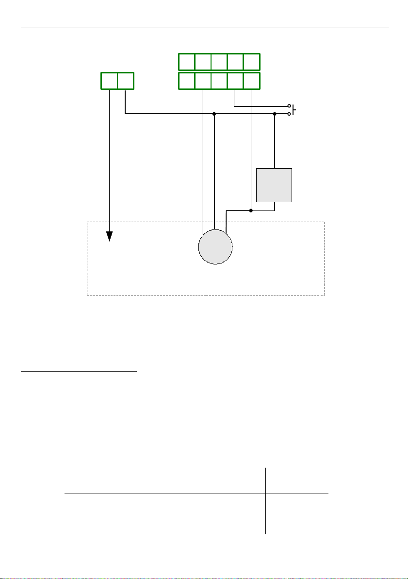
Amount of poured fluid can be changed by parameter ICCK, which is showed first in
quick view mode, while parameter ICCKLIK (see page 30). Proposed in example
system is showed in Figure 6. , and proposed circuit diagram in Figure 6.3.
More details of this example are described on page 33.
Fig re 6.2. Proposed system
16
Flow detector main valve,
controlled by relay R1
pulses to „B” input tank
User manual for universal counter with batching function SLIK-73
Fig re 6.3. Proposed circ it diagram
6.3. THE DIGITAL FILTER
To enable the connection of the simple switches as detectors, special digital filter has
been build into the device. This filter allows the counter to proper counting pulses regardless of
the vibration of the contacts of the switches.
The condition of proper counting is providing of time periods of the pulses. The filter can
be set to blocking frequencies higher than 10, 0, 30, 40, 50 ,60 ,70, 80 and 90Hz. The time
periods of stable states "0" (t0) and "1" (t1) of pulses must be not shorter than 1/ F, where F
the filtered frequency in Hz. See the table below (Tab. 6. ) to check proper periods for all
frequencies.
filter setting (F) t0, t1
input signal
frequency input type
OFF 50,0 µs /
100,0 µs
10 kHz /
5 kHz
electronic
input
10 50,0 ms 10 Hz
17
67
=
#
89 8$ 8: 8; /0
&&
!
Supply
4V DC
5 -
Controlled system
5
=
Main
valve
Flow
detector
% 1 9 $ : ; 80
8
#
User manual for universal counter with batching function SLIK-73
filter setting (F) t0, t1
input signal
frequency input type
0 5,0 ms 0 Hz
30 16,7 ms 30 Hz electronic
40 1 ,5 ms 40 Hz or contact
50 10,0 ms 50 Hz input
60 8,3 ms 60 Hz
70 7, ms 70 Hz
80 6,3 ms 80 Hz
90 5,6 ms 90 Hz
Tab. 6.2. Time periods t0 ,t1 depend on filtered freq ency.
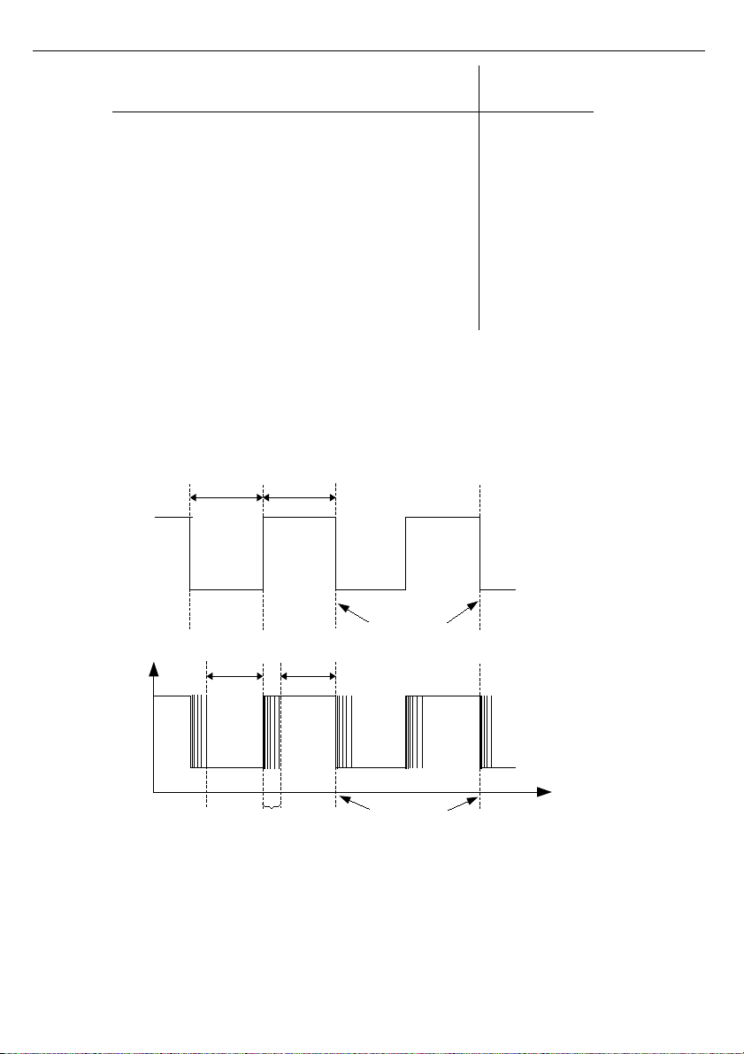
When the filter is turned off , time periods t0 i t1 must be longer than 50 µs (see Figure 6.4),
and maximum counted frequency is equal 10 kHz.
a)
b)
Fig re 6.4. The traces of signals:
a) witho t contacts oscillations, b) with contacts oscillations
1
Moments of pulses counting
t0 t1
Moments of pulses counting
t0 t1
oscillations

User manual for universal counter with batching function SLIK-73
6.4. CONTROL OF THE RELAY OUTPUTS
The control of the object (measured signal) is realized via relay outputs. Front panel LEDs
named „” indicates the state of particular relay output.
Modes of the control can be changed depend on the values of parameters I@K, IK,
IKand I'K (additional number defines particular relay).
Figure 6.5 presents the principle of relay outputs operation for example values of
parameters.
Description:
(5(6(-((C(< - time points where result exceeds thresholds value,
(6((<- time while counter keeps result at least equal to threshold value
- time between subsequent exceeds of threshold value (shorter than value of IKparameter )
M- delay of relay reaction
Fig re 6.5. Principle of relay o tp ts operation
Parameter I@K defines threshold of relay (trace: a). While normal operation of
counter, relay output can change its state to active counter value reaches (or exceeds)
the threshold (for „up” counting points A, C, E, G ). The active state of the relay (closed or
open) is defined by parameter I'K. Relay R1 reacts to counter value changes
immediately. Other relays (if available) need that counter value be same or greater than
particular threshold during at least 0 ms, to change the relay state.
19
I@Kparameter
(threshold value)
current
counter
value
displayed result
time
time
56
-
relay state
(' =
= 0)
relay state
(' =
> 0)
<
relay state
(' =CC
= 0)
relay state
(' =CC
> 0)
time
time
closed
open
a)
b)
c)
d)
e)
open
closed
open
open
closed
closed
IK
C
<
tZ
6
IK IK
time
IK IK IK

User manual for universal counter with batching function SLIK-73
It is possible to set AUTORESET function for relay R1. This function enables automatic
zeroing of the counter, after its value reaches relay R1 threshold. After zeroing, counter's
value equals to ICCK parameter.
If AUTORESET function is active, then relays other than R1 (if available) can be activated if
their thresholds are not greater than relay R1 threshold.
Maximum delay between the moment when result reaches the particular threshold and
switching on the relay output equals 15ms for OC type output and 0ms for electromechanical
relays.
If AUTORESET function is active, and counter changes its value with high speed,
relays other than R1 (if available) can not change it's states to active, because the
time between moments when counter reaches their thresholds and threshold value
of relay R1 (greater than for other relays thresholds) is to short.
Avoid of setting the „CC” parameter higher than autoreset threshold (relay R1
threshold) while AUTORESET function is active. In such case counter can work
improperly or can't work at all.
Parameter IK defines how long relay stay active after its activation by counter value (after
moment when counter has reached particular threshold).
•If parameter IK is set to I0K(thanrelay stays in active state (periods: tA ,tC ,tE ,tG) as
long as counter value is equal or higher than threshold value. (traces: b, c).
• If parameter IK is set to value different from I0K, than relay stay active during defined
time regardless of counter value (traces: d, e). In case when period (tX) between
successive exceeding of threshold value (e.g. between points B and C) is shorter than
period defined by parameter IK, activation period of relay is prolonged by IK
(every time when counter value goes up and reaches threshold).
If parameter I8K = I0K and AUTORESET function is active, relay R1 will not
change it's state to active or will be activated on very short time because of delays. If
user wants to not use particular relay (especially relay R1), its mode of operation
should be set to ”” (e.g. „'8” =””).
Parameter I'K can be set to value “modbuS”. In such case it is possible to drive
relays via RS-485 interface. In this case relays are independent on counter value, and „”
and „@” settings, and change of it's state can be done exclusively via RS-485 interface, as
presets of holding registers (see: LIST OF REGISTERS) . While parameter I'K is set to
value ”on” or ”oFF”, presets of these registers do not causes any reaction, and reading of
these registers show actual state of particular relays.
If I'Kmode is active, than after power down and up relays are inactive.
All parameters corresponding to relay outputs are described in details in chapter
”rELAy” menu.
20
i
i
i
Table of contents
Other Simex Cash Counter manuals


