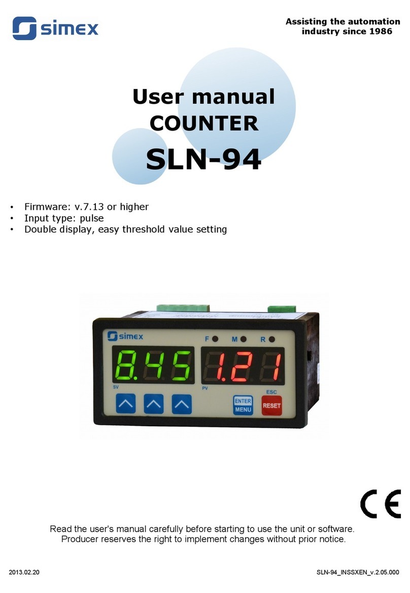
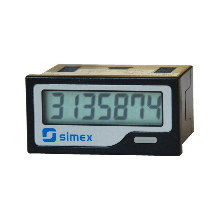
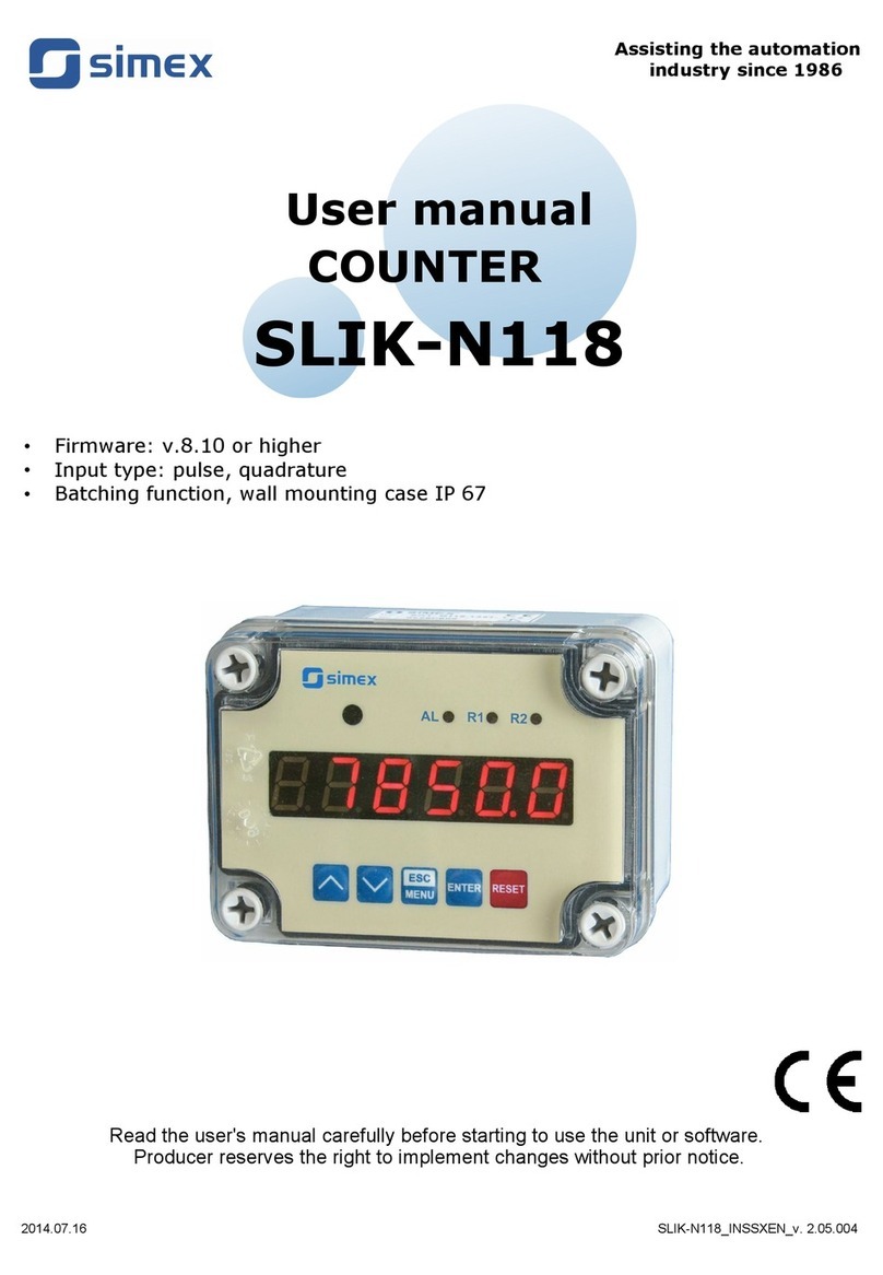
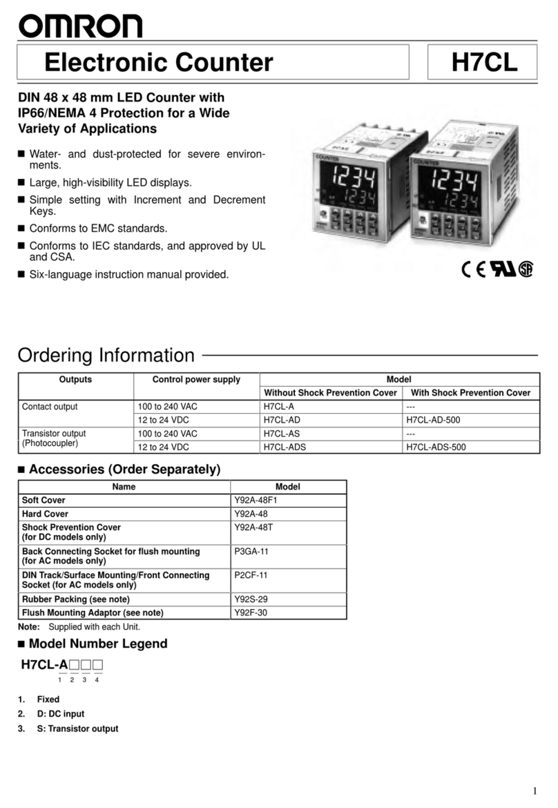
Simex SLIK-638 User manual

Assisting the automation
industry since 1986
User manual
COUNTER
SL K-638
•Firmware: v.1.00 or higher
•Input type: pulse, quadrature
•Batching function
Read the user's manual carefully before starting to use the unit or software.
Producer reserves the right to implement changes without prior notice.
2018.12.20 LIK-638_IN XEN_v.1.04.001

User manual - COUNTER SLIK-638
CONTENTS
1. BASIC REQUIREMENTS AND USER SAFETY........................................................................................3
2. GENERAL CHARACTERISTICS................................................................................................................4
3. TECHNICAL DATA......................................................................................................................................4
4. DEVICE INSTALLATION............................................................................................................................6
4.1. UNPACKING.......................................................................................................................................6
4.2. ASSEMBLY........................................................................................................................................6
4.3. CONNECTION METHOD...................................................................................................................7
4.4. MAINTENANCE................................................................................................................................14
5. FRONT PANEL DESCRIPTION................................................................................................................15
6. PRINCIPLE OF OPERATION...................................................................................................................16
6.1. MEASUREMENT MODE..................................................................................................................16
6.2. BATCHER FUNCTION.....................................................................................................................17
6.3. AUTOPRESCALER .........................................................................................................................19
6.4. THE DIGITAL FILTER......................................................................................................................20
6.5. CONTROL OF THE RELAY OUTPUTS..........................................................................................22
7. DEVICE PROGRAMMING.........................................................................................................................24
7.1. PROGRAMMING MENU..................................................................................................................24
7.2. PARAMETERS EDITION.................................................................................................................25
7.2.1. N meric parameters (digit change mode)...............................................................................25
7.2.2. N meric parameters (slide change mode)..............................................................................25
7.2.3. Switch parameters (“LIST” type).............................................................................................25
7.3. MENU DESCRIPTION.....................................................................................................................26
7.3.1. “rELAy” men ..........................................................................................................................26
7.3.2. “F nct” parameter....................................................................................................................28
7.3.3. “Pr inP” parameter...................................................................................................................28
7.3.4. “rESEt” parameter...................................................................................................................28
7.3.5. “ArESEt” parameter.................................................................................................................29
7.3.6. “FiLtEr” parameter...................................................................................................................29
7.3.7. “PArUPd” parameter................................................................................................................29
7.3.8. ”PrESCA” men .......................................................................................................................30
7.3.9. ”rS-485” men .........................................................................................................................31
7.3.10. ”SEC ” men .........................................................................................................................32
7.3.11. ”briGHt” parameter................................................................................................................34
7.3.12. ”Edit” parameter....................................................................................................................34
7.3.13. ”dEFS” parameter..................................................................................................................34
7.4. MENU STRUCTURE........................................................................................................................35
8. E AMPLES OF PRESCALER PARAMETERS CALCULATION............................................................37
9. THE MODBUS PROTOCOL HANDLING.................................................................................................38
9.1. LIST OF REGISTERS......................................................................................................................38
9.2. TRANSMISSION ERRORS DESCRIPTION....................................................................................42
9.3. EXAMPLES OF QUERY/ANSWER FRAMES.................................................................................42
10. DEFAULT AND USER'S SETTINGS LIST.............................................................................................45
2

User manual - COUNTER SLIK-638
Explanation of symbols used in the manual:
- This symbol denotes especially important g idelines concerning the installation and
operation of the device. Not complying with the g idelines denoted by this symbol
may ca se an accident, damage or eq ipment destr ction.
IF THE DEVICE IS NOT USED ACCORDING TO THE MANUAL THE USER IS
RESPONSIBLE FOR POSSIBLE DAMAGES.
- This symbol denotes especially important characteristics of the nit.
Read any information regarding this symbol caref lly
1. BASIC REQUIREMENTS AND USER SAFETY
-
- Installation should be conducted by qualified personnel . During installation all
available safety requirements should be considered. The fitter is responsible for
executing the installation according to this manual, local safety and EMC
regulations.
- GND input of device should be connected to PE wire;
- The unit must be properly set-up, according to the application. Incorrect
configuration can cause defective operation, which can lead to unit damage or
an accident.
-
-
- Neighbouring and connected equipment must meet the appropriate standards
and regulations concerning safety and be equipped with adequate overvoltage
and interference filters.
-
- Do not use the unit in areas threatened with excessive shocks, vibrations, dust,
humidity, corrosive gasses and oils.
- Do not use the unit in areas where there is risk of explosions.
3
!
i
!
!

User manual - COUNTER SLIK-638
- Do not use the unit in areas with significant temperature variations, exposure to
condensation or ice.
- Do not use the unit in areas exposed to direct sunlight.
- Make sure that the ambient temperature (e.g. inside the control box) does not
exceed the recommended values. In such cases forced cooling of the unit must
be considered (e.g. by using a ventilator).
2. GENERAL CHARACTERISTICS
Universal programmable counter type !"#$%& is equipped with many modern features
required in simple and advanced automatic control systems. The counter had been designed
for hard environment conditions, and increased usefulness.
The unit is assembled in panel mounted case with programming keyboard on front panel,
and terminals on back panel. User can use local keyboard to set all necessary parameters due
to his own requirements. Build in R -485 communication interface enables controlling of all
settings by host, and allows use of unit in advanced network systems.
Two counting inputs (pulse inputs) can operate in few different modes (as two
independent pulse inputs or single quadrature input). Additional programmable input can
change basic function of counting inputs (addition or subtraction of pulses from inputs,
change the direction of counting) or to stop counting without clearing.
Counter type !"#$%& is equipped with independent clearing input. The device can be
equipped with two or four relay (or OC type) outputs with independent thresholds, which can
be used to control external devices. The counters !"#$%&are designed for cooperation with
electronic (PNP and NPN) detectors, and mechanical detectors – switches (build in digital
filter allows connectors denouncing). All inputs are separated from ground of counter, and
power supply.
3. TECHNICAL DATA
Power supply voltage
(depending on version)
External fuse (required)
Power consumption
85...'%(...260V AC/DC; 50 ÷ 60 Hz (separated)
or 19...')...50V DC and 16...')...35V AC (separated)
T - type, max. 2 A
max. 29 VA @ 85 ÷ 260V AC/DC
max. 13 VA @ 16V ÷ 35V AC
max. 8.683 W @ 19V ÷ 50V DC
Pulse inputs
A and B inputs
C input
D input
COM
counting (terminal no. 18,19)
programmable (terminal no. 20)
reset counter (terminal no. 21)
common terminal (terminal no. 22)
4
!
!

User manual - COUNTER SLIK-638
Input levels
low level:
high level:
0V ÷ 1V
10V ÷ 30V
Max. input frequency
electronic - standard counter: 10 kHz
electronic - quadrature counter: 5 kHz
contact: 90 Hz (adjustable filter)
Display range -99999 ÷ 999999, plus decimal point
Outputs
relay:
or OC-type:
sensor power supply:
1, 2 or 4 NO 1A/250V AC (cos j = 1)
1, 2 or 4 30mA / 30VDC / 100mW
24V +5%, -10% / max. 100 mA, stabilized
Communication interface R 485, 8N1 and 8N2, Modbus RTU, not separated
Baud rate 1200 bit/s ÷ 115200 bit/s
Display LED, 6 digit, 38 mm height, red (l = 660 nm)
LED, 6 digit, 38 mm height, pure green (l = 520 nm)
LED, 6 digit, 38 mm height, blue (l = 470 nm)
Data memory non-volatile memory, EEPROM type
Protection level of device IP 67
Housing type
Housing material
Wall mounted, T-type
AB + fibreglass
Operating temperature
(depending on version)
0°C to +50°C
or -20°C to +50°C
torage temperature
(depending on version)
-10°C to +70°C
or -20°C to +70°C
Humidity
Altitude
5 to 90% no condensation
up to 2000 meters above sea level
crews tightening max. torque 0,5 Nm
Max. connection leads diameter 2,5 mm2
afety requirements according to: PN-EN 61010-1
installation category: II
pollution degree: 2
voltage in relation to ground: 300V AC
insulation resistance: >20MW
insulation strength between power supply and
input/output terminal: 1min. @ 2300V
insulation strength between relays terminal:
1min. @ 1350V
EMC according to: PN-EN 61326-1
5
Table of contents
Other Simex Cash Counter manuals
