Simlatus HD-212 User manual

Simlatus Corporation
175 Joerschke Drive, Suite A
Grass Valley, CA 95945
hone: 530-205-3437 Fax: 530-273-8482
sales@simlatus.com
www.simlatus.com
HD
HDHD
HD-
--
-212
212212
212
2 x
2 x 2 x
2 x 2
22
2
Digital
Digital Digital
Digital rotection
rotectionrotection
rotection
Switch
SwitchSwitch
Switch

Statement of Warranty
Statement of WarrantyStatement of Warranty
Statement of Warranty
Simlatus Corporation warrants its products for a period of three (3) years from
the date of shipment to be free from defects in materials and workmanship and
meets applicable published specifications. Equipment which has been operated
within its ratings and has not been sub ected to mechanical or other abuse or
modification by the purchaser, its agents, and/or employees, will, at the option of
Simlatus, be replaced or repaired if it is returned, freight prepaid, to Simlatus.
Equipment that fails under conditions other than described herein will be repaired
at the price of components and labor in affect at the time of repair.
This warranty is in lieu of all other warranties, expressed or implied, with respect
to the condition or performance of any Simlatus product, its merchantability or
fitness for a particular purpose. Simlatus Corporation is not liable for any
consequential damages.
FCC Compliance
FCC ComplianceFCC Compliance
FCC Compliance
This equipment has been tested and found to comply with the limits for a Class A
digital device pursuant to Part 15 of the FCC Rules. These limits are designed to
provide reasonable protection against harmful interference when the equipment
is operated in a commercial environment. This equipment generates, uses, and
can radiate radio frequency energy and, if not installed and used in accordance
with the instruction manual, may cause harmful interference to radio
communications. Operation of this equipment in a residential area could cause
harmful interference in which case the user will be required to correct the
interference at his own expense.
Copyright
CopyrightCopyright
Copyright
© 2016 Simlatus Corporation
Contents of this publication may not be reproduced in any form without the
written permission of Simlatus Corporation. Reproduction or reverse engineering
of copyrighted software is prohibited.
May 2016
Part Number 71
7171
71-
--
-00
0000
003
33
38
88
8

Table of Contents
Table of ContentsTable of Contents
Table of Contents
Introduction
IntroductionIntroduction
Introduction
Important Safeguards and Notices ............................................................................i
Important Warnings and Cautions ............................................................................ ii
Warnings ............................................................................................................ ii
Cautions ............................................................................................................ iii
North American Power Supply Cords ................................................................ iv
Section I
Section ISection I
Section I
eneral Description ................................................................................................ 1
Section II
Section IISection II
Section II
Specifications .......................................................................................................... 3
Section III
Section IIISection III
Section III
Installation ............................................................................................................... 4
Switches and jumpers ....................................................................................... 4
Ethernet Processor reset ................................................................................... 5
Section IV
Section IVSection IV
Section IV
Circuit Description ................................................................................................... 6
Video Path ......................................................................................................... 6
Logic ................................................................................................................. 6
Status Output .................................................................................................... 6
Power Supply/Regulators .................................................................................. 7
Section V
Section VSection V
Section V
Diagrams ................................................................................................................. 8
External Control Connector Pin Assignment ...................................................... 9
Section VI
Section VISection VI
Section VI
Ethernet Interface .................................................................................................. 10
i
Important Safeguards and Notices
Important Safeguards and NoticesImportant Safeguards and Notices
Important Safeguards and Notices
Information on the following pages provides important safety
guidelines for both Operator and Service personnel. Specific
warnings and cautions will be found throughout the manual
where they apply, but may not appear here. Please read and
follow the important safety information, noting especially those
instructions related to risk of fire, electric shock or injury to
persons.
ARNING
ARNINGARNING
ARNING
Any instructions in this manual that require opening the
Any instructions in this manual that require opening the Any instructions in this manual that require opening the
Any instructions in this manual that require opening the
equipment cover or encl
equipment cover or enclequipment cover or encl
equipment cover or enclosure are for use by qualified service
osure are for use by qualified service osure are for use by qualified service
osure are for use by qualified service
personnel only. To reduce the risk of electric shock, do not
personnel only. To reduce the risk of electric shock, do not personnel only. To reduce the risk of electric shock, do not
personnel only. To reduce the risk of electric shock, do not
perform any servicing other than that contained in the
perform any servicing other than that contained in the perform any servicing other than that contained in the
perform any servicing other than that contained in the
operating instructions unless you are qualified to do so.
operating instructions unless you are qualified to do so.operating instructions unless you are qualified to do so.
operating instructions unless you are qualified to do so.
Symbols and Their Meaning in This Man
Symbols and Their Meaning in This ManSymbols and Their Meaning in This Man
Symbols and Their Meaning in This Manual
ualual
ual
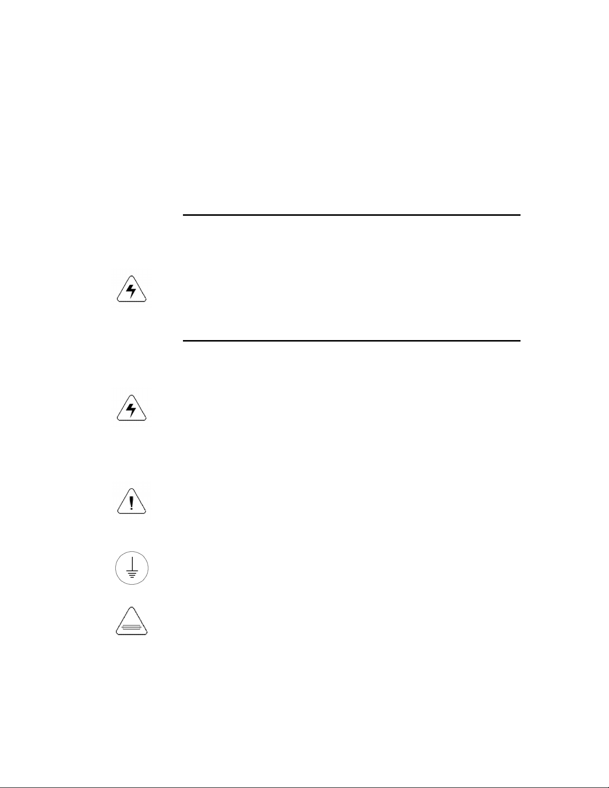
The lightning flash with arrowhead symbol, within an
equilateral triangle, alerts the user to the presence of
“dangerous voltage” within the product’s enclosure that may be
of sufficient magnitude to constitute a risk of electric shock to
persons.
The exclamation point within an equilateral triangle alerts the
user to the presence of important operating and maintenance
(servicing) instructions in the literature accompanying the
appliance.
This symbol represents a protective grounding terminal. Such
a terminal must be connected to earth ground prior to making
any other connections to the equipment.
The fuse symbol indicates that the fuse referenced in text must
be replaced with one having the ratings indicated.

ii
Important arnings and
Important arnings andImportant arnings and
Important arnings and
Cautions
CautionsCautions
Cautions
arnings
arningsarnings
arnings
•Heed all warnings on the unit and in the operating instructions.
•Do not use this product in or near water.
•Disconnect ac power before installing any options.
•This product is grounded through the grounding conductor of
the power cord. To avoid electrical shock, plug the power cord
into a properly wired receptacle before connecting the product
inputs or outputs.
•Route power cords and other cables so that they are not likely
to be damaged.
•Disconnect power before cleaning. Do not use liquid or aerosol
cleaners; use only a damp cloth.
•Dangerous voltages exist at several points in this product. To
avoid personal injury, do not touch exposed connections and
components while power is on.
•Do not wear hand jewelry or watches when troubleshooting high
current circuits, such as the power supplies.
•During installation, do not use the door handles or front panels
to lift the equipment as they may open abruptly and injure you.
•To avoid fire hazard, use only the specified correct type, voltage
and current rating as referenced in the appropriate parts list for
this product. Always refer fuse replacements to qualified service
personnel.
•To avoid explosion, do not operate this product in an explosive
atmosphere unless it has been specifically certified for such
operation.
•Have qualified personnel perform safety checks after any
completed service.

iii
arnings (continued)
arnings (continued)arnings (continued)
arnings (continued)
•If equipped with redundant power, this unit has two power
cords. To reduce the risk of electrical shock, disconnect both
power supply cords before servicing.
•This equipment may employ laser(s). If it does, they comply
with the current construction requirements of the code of
Federal regulations, title 21, chapter I, subchapter J, sections
1010.2 and 1010.3 and sections 1040.10 and 1040.11.
•Do not attempt to view light output of the laser transmitter, eye
damage may result. Always use an optical power meter to verify
laser output.
•To prevent injury:
Never install telephone wiring during a lightning storm.
Never install telephone jacks in wet locations unless the jack is
specifically designed for wet locations.
Never touch uninsulated telephone wires or terminals unless the
telephone line has been disconnected at the network interface.
Use caution when installing or modifying telephone lines.
Cautions
CautionsCautions
Cautions
•hen installing this equipment, do not attach power cord to
building surfaces.
•To prevent damage to equipment when replacing fuses, locate
and correct the trouble that caused the fuse to blow before
applying power.
•Verify that all power supply lights are off before removing power
supply or servicing equipment.
•Use only specified replacement parts.
•Follow static precautions at all times when handling this
equipment.

iv
Cautions (continued)
Cautions (continued)Cautions (continued)
Cautions (continued)
•Leave the back of the frame clear for air exhaust cooling and to
allow room for cabling. Slots and openings in the cabinet are
provided for ventilation. Do not block them.
•Front door is part of fire enclosure and should be kept closed
during normal operation.
•This product should be powered on as described in the manual.
To prevent equipment damage select the proper line voltage at
the ac input connector as described in the Installation
documentation.
•To prevent damage to this equipment read the instructions in
this document for proper input voltage range selection.
•To reduce the risk of electric shock, ensure that the two power
supply cords are each plugged into a separate branch circuit.
•Circuit boards in this product are densely populated with surface
mount and ASIC components. Special tools and techniques are
required to safely and effectively troubleshoot and repair
modules that use SMT or ASIC components. For this reason,
service and repair of RJM products incorporating surface mount
technology are supported only on a module exchange basis.
Customers should not attempt to troubleshoot or repair modules
that contain SMT components. RJM assumes no liability for
damage caused by unauthorized repairs. This applies to both
in- and out-of-warranty products.
North American Power Sup
North American Power SupNorth American Power Sup
North American Power Supply Cords
ply Cordsply Cords
ply Cords
This equipment is supplied with molded grounding plug (NEMA 5-
15P) at one end and molded grounding connector (IEC 320-C13) at
the other end. Conductors are CEE color coded, light blue (neutral),
brown (line) and green/yellow (ground).
Operation of this equipment at voltages exceeding 130 VAC will
require power supply cords which comply with NEMA
configurations.

v
Note:
Note:Note:
Note:
This equipment has been tested and found to comply with the limits
for a class A digital device, pursuant to Part 15 of the FCC Rules.
These limits are designed to provide reasonable protection against
harmful interference when the equipment is operated in a
commercial environment. This equipment generates, uses, and can
radiate radio frequency energy and, if not installed and used in
accordance with the instruction manual, may cause harmful
interference, in which case the user will be required to correct the
interference at his own expense.

SECTION 1
HD-212
General description
The Simlatus HD-212 functions as an input transfer system that can switch
between two high definition or SDI digital video input signals, and B. This is
accomplished automatically using the internal signal detect, or manually using
either the local or remote select /B switch. transfer module occupies one-half
of a 1RU frame. The 1RU frame is designed to house a maximum of two RTU
units. Each unit operates independently from the other. They do share a common
power supply.
The frame has space for two power supplies for redundancy, with the output of
the supply voltage diode OR’d on the main module with the output of the other
supply. Each supply has its own C line connection. If either supply fails or its
C line fails, then the other supply will keep the unit running.
The switchover is determined by the presence of video on the in-use video input.
If video is interrupted on the selected (in-use) input and if video is present on the
non-selected input, then a switch to the non-selected input will occur. If no video
is present on the non-selected input then no switch will occur. In the digital HD-
212 loss of video is not the loss of the data stream, but actually the loss of the
SMPTE TRS (E V-S V). The presence/absence detector can be set to SD-only,
HD-only or UTO detection of either. When in the UTO mode, the unit will also
detect DVB- SI.
toggle switch is provided on the module to allow the unit to operate in either
automatic or manual mode. The unit can be operated manually at any time by
pushing the red button located inside the hole in the front cover, or by providing
an external GPI closure to ground.
Once a switchover has been completed from one input to the other, the system
will not automatically return to the first input upon restoration of signal. If it is
desired that the unit be operated from that first source, then the return must be
accomplished manually. This is true if the switch has occurred from the B input to
the input. If the switch has occurred from input to input B, then there is an
additional feature that allows the unit to return-to- upon re-activation of the
signal.
Upon loss of power to the changeover unit or the removal of the processor
module, relays are provided that will allow the Input signal to be re-routed to
the #1 On-Line output, thereby bypassing the changeover function.
The video inputs terminate in 75 ohms.

2
When power is applied, the signal input is selected as the default mode.
The output of the HD-212 can be either the or B input. There are three 75Ω
BNC connectors for the On-Line output and one BNC connector for the Off-Line
output.
There is an EXT CONTROL connector, which is a female 9 pin ‘D’. The External
Control provides for external /B transfer and also /B signal and power supply
health monitoring of the HD-212. Refer to page 9 for the proper pinout.
second EXT CONTROL connector is provided, which is an RJ-45. This
connector is only utilized if the optional Ethernet Interface module is included.
The connector provides a path from the interface module to an external network
connection.

3
SECTION II
SECTION IISECTION II
SECTION II
HD
HDHD
HD-
--
-212
212212
212
Specifications
SpecificationsSpecifications
Specifications
Video:
Video:Video:
Video:
Inputs:
Number 2
Input type 75Ω, BNC per IEC 169-8
Signal level 800mV ±10%
Return loss >13dB at 270Mb
Data rate 270Mb or 1.485Gbps
Equalization utomatic
>300 meters Belden 1694 @270Mb
>100 meters Belden 1694
@1.485Gbps
Outputs:
Number 3 – On-line
1 – Off-line
Impedance 75Ω, BNC
Signal level 800mV ±10%
Return loss >15dB at 270Mb
Specifications:
Jitter HD – 125ps
SDI – 150ps
Temperature:
Temperature:Temperature:
Temperature:
Performance 0 to 40 degrees centigrade
Operating 0 to 50 degrees centigrade
Humidity 90% non-condensing
Power requirements
Power requirementsPower requirements
Power requirements:
::
:
115/230V C, 50/60 Hz, 20W
Size
SizeSize
Size:
::
:
1.75” x 19” x 10”
Weight
WeightWeight
Weight:
::
:
≈7 lbs 3 kg
* Specifications and design are subject to change without notice.

4
SECTION III
SECTION IIISECTION III
SECTION III
HD
HDHD
HD-
--
-212
212212
212
Installation
InstallationInstallation
Installation
The HD-212 input transfer unit is a one rack-unit frame designed to be mounted
in a standard 19” equipment rack. There are no special cooling requirements
though care should be taken to ensure that extremely hot equipment not be
installed directly beneath. It is also recommended that, if possible, one rack-unit
of space be left above the unit.
Unless specified at the time of order, the HD-212 is shipped from the factory for
nominal 117V C 60Hz power. The unit comes shipped with a 120V type C
plug. If it is desired to operate at 230V C 50Hz, a selector switch must be set on
the power supply. The supply is removed from the frame, the switch set to
230V C, and the supply replaced in the frame.
The two HD/SDI video inputs and B are internally terminated at 75Ω. The On-
Line and Off-Line outputs are 75Ω. Unused outputs should be terminated with
precision 75Ω terminations.
Switches and jumpers
Switches and jumpersSwitches and jumpers
Switches and jumpers
When the unit is in the automatic mode, if the signal fails on the input the unit
switches to the B input. rotary switch (SW4)
(SW4)(SW4)
(SW4) is provided on the module to allow
the user to define whether the unit returns to the input upon return of the
signal or that the unit remains on the B input until it is manually returned to the
input. The return-to- -signal mode can be delayed by an adjustment of this
switch from position 1 to 5 to allow from 1 to 5 seconds after the return of the
signal before the unit switches back to the input. The zero (0) position of the
switch defeats the return function and dictates that the signal remain-on-B after a
switchover. The switch is set at the factory for 0 (do not return) operation.
toggle switch (SW2)
(SW2)(SW2)
(SW2) is located near the front of the module. This switch
permits selection of the unit in either the automatic ( UTO) or manual (M N)
mode of operation. Placing the switch in the DOWN position places the module
in the UTOM TIC mode of operation. Placing the toggle switch in the UP
position places the module in the M NU L mode.

5
The HD-212 can automatically detect whether the input signals are HD or SDI.
4-pin jumper
(JP1)
(JP1) (JP1)
(JP1) is provided to
allow the unit to automatically or manually set
the standard. If the jumper is placed between pins 1 & 2, the standards detection
will be automatic. Placing the jumper between pins 2 & 3 will set the unit to SD
only and placing the jumper between pins 3 & 4 will set the unit to HD only. The
jumper is set at the factory to UTO.
The 6-pin header (JP2)
(JP2)(JP2)
(JP2) is for factory use only.
LED lamps are provided on the module to provide certain operating indications.
Each LED block contains three lamps. In all cases the center lamp is not used.
D301 indicates the presence of the signal and the B signal. It can be viewed
through light pipes in the front cover of the frame. D302 indicates whether the
input or the B input is on-line. This also can be viewed through light pipes in the
front cover of the frame. Elements of D303 indicates the presence of +5 volts
from each of the two on-board +5V regulators. The front cover must be removed
to observe these LEDs.
Reset Default Settings
Reset Default SettingsReset Default Settings
Reset Default Settings
The Ethernet Processor module can be restored to factory default settings. To
accomplish this, proceed as follows:
1. Remove the RTU module from the frame.
2. long the left-hand side of the module, locate the black jumper at JP1
JP1JP1
JP1.
3. Remove the jumper.
4. Just to the left of the Ethernet Processor sub-module, locate a 2-pin
header JP3
JP3JP3
JP3.
5. Place the black jumper on JP3
JP3JP3
JP3.
6. Re-insert the RTU module in the frame and allow it to power up.
7. Remove the module and remove the jumper from JP3
JP3JP3
JP3.
8. Replace the jumper on JP1
JP1JP1
JP1.
9. Replace the RTU module in the frame.
10. The IP address will return to the default number. The processor must be
re-programmed with the appropriate IP address.

6
SECTION
SECTIONSECTION
SECTION
IV
IVIV
IV
HD
HDHD
HD-
--
-212
212212
212
Circuit Description
Circuit DescriptionCircuit Description
Circuit Description
Video Path:
Video Path:Video Path:
Video Path:
Each of the two inputs ( & B) connects to an automatic cable equalizer (U101 &
U201), which compensates for high frequency cable attenuation. Each equalizer
output connects to the input of two Gennum 1560 de-serializers (U103 & U203).
Each 1560 has two inputs; one from each of the equalizers. The 1560 locks an
oscillator (U102 & U202) to the input data stream, and also detects and locks to
SMPTE TRS framing words in the signal. It then outputs a LOCK signal when a
valid input signal is present. The 1560 also re-clocks the serial data and outputs
a regenerated serial stream.
One 1560 drives the on-line output drivers (U1 & U2) and the other drives the off-
line output driver (U3).
Logic:
Logic:Logic:
Logic:
Xilinx CPLD (U205) contains all logic to switch the Gennum 1560 inputs to the
proper output, based on the LOCK (video present) signals. The CPLD outputs
status information to the front panel LEDs, the remote control connector and the
Ethernet interface, if installed.
Status Outputs:
Status Outputs:Status Outputs:
Status Outputs:
Status is available for different functions on the External Control GPI connector.
Each output is an open collector output. There are five such outputs. The first
one is input health and video present, which will go to a high state if input
health is bad or video is not present. The second output is the same as the first
but for the B input health and B video present. The third output indicates the
health of the power supplies in the frame. If either supply goes down then the
output goes high. The fourth status output is for switch selection status. low on
this output indicates that the input is selected and a high indicates that the B
input is selected. The final output indicates that a switchover has occurred. It
provides a momentary low. n external alarm can be connected to this output.

7
Power Supply / Regulators:
Power Supply / Regulators:Power Supply / Regulators:
Power Supply / Regulators:
The unregulated voltage to the voltage regulators on the main board comes from
either of two power supplies that can be removed at the front of the RTU frame
for service and replacement. Each unregulated supply has an input fuse and a
115/230V C selector switch, and contains the circuitry that monitors the positive
output. dual color LED on the front of the power supply displays its health.
Green indicates normal operation, or healthy condition. Red indicates either no
C present, or a problem with that supply. The output of the supply is diode OR’d
to its respective supply bus.
There are four regulators on the main board. U401 regulates the +5 volts from
power supply , U402 the +5 volts from power supply B. The two outputs are
diode OR’d to provide the main +5 volts to the module. U403 regulates the +3.3
volts and U404 regulates the +1.8 volts.
The outputs of U401 and U402 are fed to separate voltage monitors, U405 and
U406. The outputs of these monitors are connected together and provide the PS
Health signal to the External Control connector.

8
SECTION V
SECTION VSECTION V
SECTION V
HD
HDHD
HD-
--
-212
212212
212
Diagrams
DiagramsDiagrams
Diagrams
External Control Connector Pin ssignments

9
HD
HDHD
HD-
--
-212
212212
212
EXTERN L CONTROL CONNECTOR
EXTERN L CONTROL CONNECTOREXTERN L CONTROL CONNECTOR
EXTERN L CONTROL CONNECTOR
9
99
9-
--
-PIN ‘D’
PIN ‘D’PIN ‘D’
PIN ‘D’
1 Power Supply Health (Low = Healthy)
2 Input B Video Present/Input Health
(Low = Video Present and Input Healthy)
3 Switch-occurred larm (Momentary Low)
4 Select Input ( ctive Low, Momentary Pulse)
5 GND
6 Input Video Present/Input Health
(Low = Video Present and Input Healthy)
7 Input Selection Status (Low = Input Selected)
8 n/c
9 Select Input B ( ctive Low, Momentary Pulse)

10
SECTION VI
SECTION VISECTION VI
SECTION VI
HD
HDHD
HD-
--
-212
212212
212
Ethernet Interface
Ethernet InterfaceEthernet Interface
Ethernet Interface
core processor is included to allow the HD-212 to communicate through an
Ethernet interface to an external control device. This communication allows for
status monitoring and switchover control.
The installation consists of installing the processor sub-module into the mating
connector on the HD-212 with the RJ-45 facing forward. Then connect the
supplied cable between the RJ-45 connector on the processor sub-module and
the RJ-45 connector on the HD-212.
The jumper (JP3)
(JP3)(JP3)
(JP3) is provided to reset the processor to the default parameters.
To reset, remove the module from the frame, short the two pins on JP3 and plug
the module into the frame. This will reset the processor. Remove the module and
remove the short to return to normal operation.
Table of contents


