manuals.online logo
Brands
  1. Home
  2. •
  3. Brands
  4. •
  5. SMC Networks
  6. •
  7. Switch
  8. •
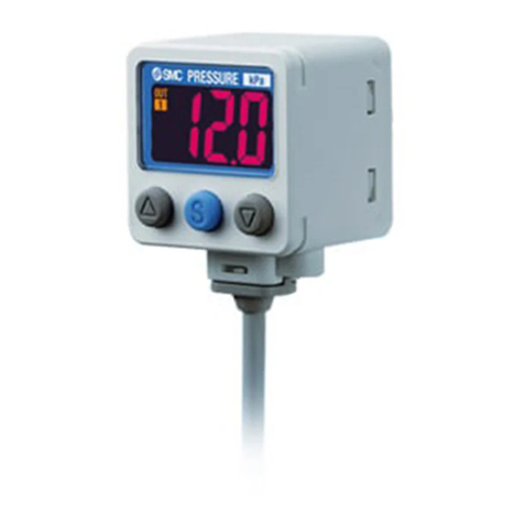
  9. SMC Networks ZSE40A User manual

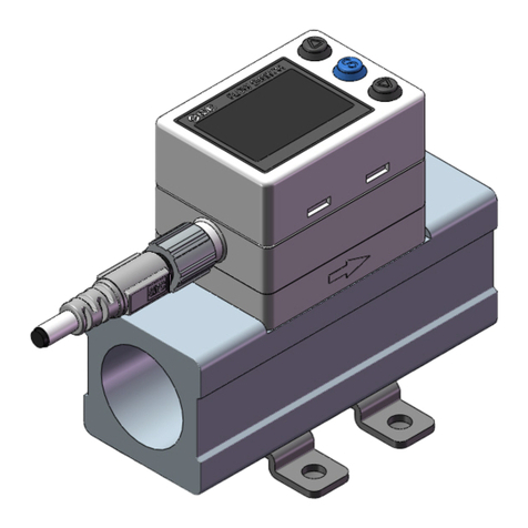
SMC Networks ZSE40A User manual

Other manuals for ZSE40A

4

This manual suits for next models

21

Other SMC Networks Switch manuals

SMC Networks SMC EZ Switch 10/100/1000 SMCGS8P-Smart User manual

SMC Networks

SMC Networks SMC EZ Switch 10/100/1000 SMCGS8P-Smart User manual

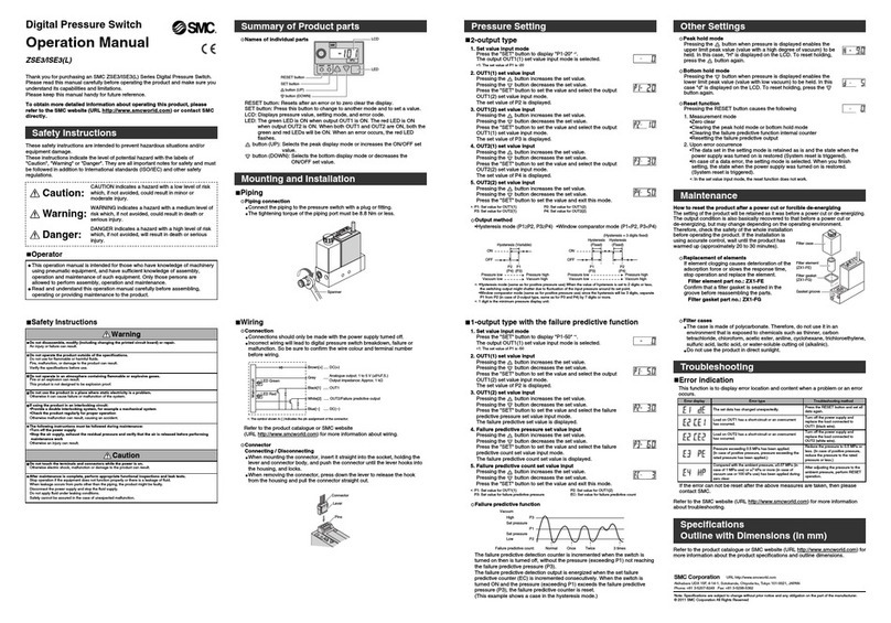
SMC Networks ZSE80 User manual

SMC Networks

SMC Networks ZSE80 User manual

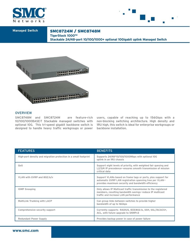
SMC Networks 8724M INT User manual

SMC Networks

SMC Networks 8724M INT User manual

SMC Networks SMCGS10C-Smart Programming manual

SMC Networks

SMC Networks SMCGS10C-Smart Programming manual

SMC Networks Reed Switch Solid State Switches User manual

SMC Networks

SMC Networks Reed Switch Solid State Switches User manual

SMC Networks TigerSwitch 10 User manual

SMC Networks

SMC Networks TigerSwitch 10 User manual

SMC Networks SMC TigerStack 1000 SMC8724M Programming manual

SMC Networks

SMC Networks SMC TigerStack 1000 SMC8724M Programming manual

SMC Networks TigerStack II SMC8848M User manual

SMC Networks

SMC Networks TigerStack II SMC8848M User manual

SMC Networks D-G5BA Series Instruction Manual

SMC Networks

SMC Networks D-G5BA Series Instruction Manual

SMC Networks TigerStack II SMC8926EM User manual

SMC Networks

SMC Networks TigerStack II SMC8926EM User manual

SMC Networks D-R K Series User manual

SMC Networks

SMC Networks D-R K Series User manual

SMC Networks TigerStack II SMC8926EM User manual

SMC Networks

SMC Networks TigerStack II SMC8926EM User manual

SMC Networks 8028L2 Programming manual

SMC Networks

SMC Networks 8028L2 Programming manual

SMC Networks GS24C-SMART User manual

SMC Networks

SMC Networks GS24C-SMART User manual

SMC Networks 6924VF - FICHE TECHNIQUE User manual

SMC Networks

SMC Networks 6924VF - FICHE TECHNIQUE User manual

SMC Networks EZ Switch SMC-EZ1024FDT User manual

SMC Networks

SMC Networks EZ Switch SMC-EZ1024FDT User manual

SMC Networks D-M9K User manual

SMC Networks

SMC Networks D-M9K User manual

SMC Networks EZSwitch SMCGS24C-Smart User manual

SMC Networks

SMC Networks EZSwitch SMCGS24C-Smart User manual

SMC Networks PFMC7-L Series User manual

SMC Networks

SMC Networks PFMC7-L Series User manual

SMC Networks TigerStack II SMC8848M User manual

SMC Networks

SMC Networks TigerStack II SMC8848M User manual

SMC Networks ZSE10F Series User manual

SMC Networks

SMC Networks ZSE10F Series User manual

SMC Networks EZ 10/100 User manual

SMC Networks

SMC Networks EZ 10/100 User manual

SMC Networks PF3A801H-L User manual

SMC Networks

SMC Networks PF3A801H-L User manual

SMC Networks 8748L2 - annexe 1 User manual

SMC Networks

SMC Networks 8748L2 - annexe 1 User manual

Popular Switch manuals by other brands

Aeotec ZWA003-S operating manual

Aeotec

Aeotec ZWA003-S operating manual

TRENDnet TK-209i Quick installation guide

TRENDnet

TRENDnet TK-209i Quick installation guide

Planet FGSW-2022VHP user manual

Planet

Planet FGSW-2022VHP user manual

Avocent AutoView 2000  AV2000BC AV2000BC Installer/user guide

Avocent

Avocent AutoView 2000 AV2000BC AV2000BC Installer/user guide

Moxa Technologies PT-7728 Series user manual

Moxa Technologies

Moxa Technologies PT-7728 Series user manual

Intos Electronic inLine 35392I operating instructions

Intos Electronic

Intos Electronic inLine 35392I operating instructions

Cisco Catalyst 3560-X-24T Technical specifications

Cisco

Cisco Catalyst 3560-X-24T Technical specifications

Asante IntraCore IC3648 Specifications

Asante

Asante IntraCore IC3648 Specifications

Siemens SIRIUS 3SE7310-1AE Series Original operating instructions

Siemens

Siemens SIRIUS 3SE7310-1AE Series Original operating instructions

Edge-Core DCS520 quick start guide

Edge-Core

Edge-Core DCS520 quick start guide

RGBLE S00203 user manual

RGBLE

RGBLE S00203 user manual

Thrustmaster FLIGHT SIMULATOR X quick guide

Thrustmaster

Thrustmaster FLIGHT SIMULATOR X quick guide

Southwire SURGE GUARD 41390 RVC troubleshooting guide

Southwire

Southwire SURGE GUARD 41390 RVC troubleshooting guide

Buhler Nivotemp NT 61 Brief instructions

Buhler

Buhler Nivotemp NT 61 Brief instructions

Kramer VS-41HDCP user manual

Kramer

Kramer VS-41HDCP user manual

Techly IDATA AU-270 user manual

Techly

Techly IDATA AU-270 user manual

Belkin F1U109 user manual

Belkin

Belkin F1U109 user manual

Emerson Rosemount 2521 Series quick start guide

Emerson

Emerson Rosemount 2521 Series quick start guide

manuals.online logo
manuals.online logoBrands
  • About & Mission
  • Contact us
  • Privacy Policy
  • Terms and Conditions

Copyright 2025 Manuals.Online. All Rights Reserved.

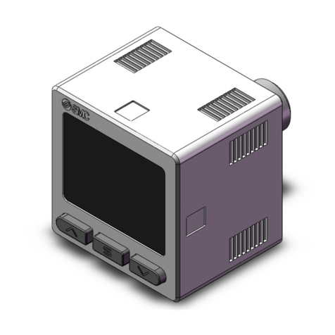
Series ZSE40A(F)/ISE40A
2-Color Display High Precision
Digital Pressure Switch
The settings of the master pressure switch (source of copy) can be copied
to the slave pressure switches.
쎲
Reduction in setting work
쎲
Prevention of mistakes in setting
Easy handling!Easy handling!
123
Push
Push
Air, Non-corrosive gas, Non-flammable gasAir, Non-corrosive gas, Non-flammable gasAir, Non-corrosive gas, Non-flammable gas
CopyCopyCopy
Easy handling!
Raised rubber switch
buttons for easy and
comfortable operation
See abnormal values at a glance.See abnormal values at a glance.See abnormal values at a glance.
IP65
compliant
RoHS
compliant
Applicable
fluid
CanCan copycopy to up toto up to
1010
switches simultaneously.switches simultaneously.
Can copy to up to
10
switches simultaneously.
Master pressure switch
(source of copy)
1 switchSlave
pressure
switch
3-step setting-step setting3-step setting 2-color display-color display2-color display
Adjust to the set-value
by the or button.
Completion
of setting
2 switches 10 switches
CAT.NAS100-79A
Piping Variations
Series
Mounting Variations
Space-saving
Rated pressure
range
Series
–14.5 to 145.0 psi
145 psi
0
–14.5 psi
ISE40A
(positive pressure)
0.00 to –14.69 psi
–14.69 psi
0
ZSE40A
(vacuum pressure)
–14.50 to 14.50 psi
–14.5 psi
14.5 psi
0
ZSE40AF
(compound pressure)
0.1 psi0.02 psi
Withstand
pressure
Min. unit setting
218 psi72.5 psi72.5 psi
0.01 psi
Output
R1/8, NPT1/8 (With M5 female thread), Rc1/8, G1/8, M5 female thread
ø4, ø6 one-touch fitting
Piping
Set pressure
range
–15.2 to 152.3 psi
–15.22 to 15.22 psi
1.45 to –15.23 psi
(Only the displayed value is changed,
and there is no effect on the accuracy.)
The value disappears
and decimal points
start flashing.
∗The set-value can be checked while the keys are locked.
OUT
OUT
1
2
1/1000 1/100
OUT
OUT
1
2
OUT
OUT
1
2
OUT
OUT
1
2
OUT
OUT
1
2
An optional 3-digit
value is entered.
Secret code setting function
A function to prevent operation by anyone other than the
designated operator while the keys are locked.
Power-saving function
The display can be turned off to save the power consumption.
(Power consumption reduced by max. 20%)
Resolution conversion function
The flickering on the display can be eliminated.
MPa/kPa switching function
The indication unit for vacuum, compound pressure and
positive pressure can be integrated into either MPa or kPa.
OUT
OUT
1
2
Panel mounting
Bracket ABracket BBracket D
R1/8, NPT1/8
M5 x 0.8 Rc1/8, G1/8
Rc1/8, G1/8
ø4, ø6
one-touch fitting M5 x 0.8
Interchangeable with the ZSE40/ISE40 series for mounting
44
40.240.240.2
New
Series ZSE/ISE40A
Series ZSE/ISE40
• NPN or PNP open collector 2 outputs + Copy function
• NPN or PNP open collector 2 outputs +
Analog output (voltage or current)/Auto-shift input
Direct mounting
(Wall mounting)
Stick the
label (enclosed
with the product)
of a desired unit
seal.
Features 1
How to Order
Series
ZSE40A(F)/ISE40A
2-Color Display High Precision
Digital Pressure Switch
®
ISE40A 01 X P
ZSE40A 01 Y P
Rated pressure range
ISE40A –14.5 to 145.0 psi
Output specifications
NPN open collector 2 outputs + Analog voltage/Auto-shift switching
PNP open collector 2 outputs + Analog voltage/Auto-shift switching
NPN open collector 2 outputs + Analog current/Auto-shift switching
PNP open collector 2 outputs + Analog current/Auto-shift switching
NPN open collector 2 outputs + Copy function
PNP open collector 2 outputs + Copy function
R
T
S
V
X
Y
Bracket A
Bracket B
Bracket D
Panel mount adapter
ZS-24-A
ZS-24-B
ZS-24-D
ZS-35-C
ZS-35-D
ZS-35-F
ZS-35-G
Panel mount adapter +
Front protective cover
A
B
D
E
F
01 N01 W1
WF1
M5 C4 C6
Option 1
Description
Symbol
Part no.
Piping
Part no. Option
Rated pressure range
ZSE40A
ZSE40AF
0.00 to –14.69 psi
–14.50 to 14.50 psi
Made to Order
Option 2
Symbol
Nil
K
Calibration certificate
Symbol
X501
X531
Specifications/Description
Lead wire length 3 m
M12 4-pin pre-wired
connector
(Lead wire length 100 mm)
Unit specifications
Option 1∗
Combination of piping specifications with option 1 and part numbers of options
None
Bracket A
A
Bracket B
B
Bracket D
D
Panel mount adapter
01/N01
W1/WF1/M5/C4/C6
W1/WF1/M5/C4/C6
Panel mount adapter +
Front protective cover
E
F
Nil
Piping
specifications
01
N01
W1
WF1∗
M5∗
C4∗
C6∗
01/N01
∗Some options are unavailable depending on the piping specifications.
Refer to “Combination of piping specifications with option 1 and part
numbers of options”.
When optional parts are required separately,
use the following part numbers to place an order.
Refer to page 17 for details.
∗Made to Order
For vacuum/
compound pressure
For positive pressure
R1/8
(With M5 female thread)
NPT1/8
(With M5 female thread)
Rc1/8
G1/8
M5 x 0.8
(Female thread)
ø4 one-touch fitting
ø6 one-touch fitting
ZS-24-A
ZS-24-B
ZS-24-D
ZS-35-C
ZS-35-D
ZS-35-F
ZS-35-G
Bracket A With 2 mounting screws of each M3 x 5L, M4 x 5L
Bracket B With 2 mounting screws M4 x 5L
Bracket D With 2 mounting screws of each M3 x 5L, M4 x 5L
Panel mount adapter (Piping: For 01/N01)
Panel mount adapter
(Piping: For W1/WF1/M5/C4/C6)
Panel mount adapter + Front protective cover
(Piping: For 01/N01)
Panel mount adapter + Front protective cover
(Piping: For W1/WF1/M5/C4/C6)
Options/Part No.
With unit switching function Note 1)
Fixed SI unit Note 2)
With unit switching function Note 1)
(Initial value psi)
Nil
M
P
Note 1) Under the New Measurement
Law, sales of switches with the
unit switching function are not
allowed for use in Japan.
Note 2) Fixed unit:
For vacuum/compound
pressure: kPa
For positive pressure: MPa
M5 x 0.8
ø4, ø6 one-touch fitting
Rc1/8, G1/8
Rc1/8, G1/8
R1/8, NPT1/8
M5 x 0.8
1
Specifications
Piping Specifications
Part no. 01 N01 W1 WF1
78 g 79 g 97 g 104 g 101 g
M5 C4 C6
ø6 one-touch
fitting
ø4 one-touch
fitting
ZDC2, POM, Stainless steel 304,
C3604 (Electroless nickel plated)
O-ring: HNBR
M5 x 0.8
female thread
G1/8
Silicon
Rc1/8
ZDC2
O-ring: HNBR
NPT1/8
(With M5
female thread)
R1/8
(With M5
female thread)
C3602 (Electroless nickel plated)
O-ring: HNBR
Port size
Sensor pressure
receiving area
Model ZSE40A (vacuum pressure)
0.00 to –14.69 psi
1.45 to –15.23 psi
72.5 psi
0.01 psi
–14.50 to 14.50 psi
–15.22 to 15.22 psi
72.5 psi
0.02 psi
Air, Non-corrosive gas, Non-flammable gas
12 to 24 VDC ±10%, Ripple (p-p) 10% or less (with power supply polarity protection)
45 mA or less
NPN or PNP open collector 2 outputs (Selectable)
80 mA
28 V (at NPN output)
1 V or less
2.5 ms (with anti-chattering function: 20, 100, 500, 1000, 2000 ms)
Yes
±0.2% F.S. ±1 digit
Variable (0 or above) Note 1)
1 to 5 V ±2.5% F.S.
4 to 20 mA ±2.5% F.S.
Maximum load impedance: 300 Ω(Power supply voltage 12 V)
600 Ω(Power supply voltage 24 V)
Minimum load impedance: 50 Ω
Oilproof heavy-duty vinyl cable
ø3.5, 2 m Conductor area: 0.15 mm2(AWG26) Insulator O.D.: 0.95 mm
0.6 to 5 V ±2.5% F.S.
2.4 to 20 mA ±2.5% F.S.
–14.5 to 145.0 psi
–15.2 to 152.3 psi
218 psi
0.1 psi
Rated pressure range
Display/Set pressure range
Withstand pressure
Display/Minimum unit setting
Applicable fluid
Power supply voltage
Current consumption
Switch output
Repeat accuracy
Hysteresis
Maximum load current
Maximum applied voltage
Residual voltage
Response time
Short circuit protection
Hysteresis mode
Window comparator mode
Voltage
output
Analog
output
Current
output
Output voltage
(Rated pressure range)
Linearity
Output impedance
Output current
(Rated pressure range)
Linearity
Load impedance
Enclosure
Operating temperature range
Operating humidity range
Withstand voltage
Insulation resistance
Vibration resistance
Impact resistance
ZSE40AF
(compound pressure)
ISE40A (positive pressure)
Note 1) If the applied voltage fluctuates around the set-value, the hysteresis must be set to a value more than the fluctuating width, otherwise chattering will occur.
Note 2) When the analog voltage output is selected, the analog current output cannot be selected.
Note 3) When the analog current output is selected, the analog voltage output cannot be selected.
Note 2)
Note 3)
±1% F.S. or less
Approx. 1 kΩ
±1% F.S. or less
Non-voltage input (Reed or Solid state), Low level: 0.4 V or less, 5 ms or longer input
3 1/2-digit, 7-segment, 2-color LCD (Red/Green)
±2% F.S. ±1 digit (Ambient temperature of 77 ±5°F)
Lights up when output is turned ON. OUT1, OUT2: Orange
IP65
Operating: 23 to 122°F, Stored: 14 to 140°F (No freezing or condensation)
Operating/Stored: 35 to 85% RH (No condensation)
1000 VAC for 1 minute between live parts and case
50 MΩor more between live parts and case (at 500 VDC Mega)
10 to 150 Hz at whichever is smaller of 1.5 mm amplitude or 20 m/s2acceleration,
in X, Y, Z directions, for 2 hours each (De-energized)
100 m/s2in X, Y, Z directions, 3 times each (De-energized)
±2% F.S. (Based on 77°F)
CE marking, UL (CSA), RoHS compliance
Auto-shift input
Display
Display accuracy
Indicator light
Temperature characteristics
Lead wire
Standards
Environment
resistance
Material
of parts
in contact
with fluid
Weight
Piping port
2
Series ZSE40A(F)/ISE40A
Range
For vacuum pressure
For compound pressure
For positive pressure
Rated pressure range
0.00 to –14.69 psi
–14.50 to 14.50 psi
–14.5 to 145.0 psi
A
1.47 psi
—
–14.5 psi
B
0
–14.50 psi
0
C
–14.69 psi
14.50 psi
145.0 psi
Analog Output
Descriptions
Voltage output
1
0.6
Pressure
Analog output [V]
5
BA C
Current output
4
2.4
Pressure
Analog output [mA]
20
BA C
Displays the current pressure, set mode, selected
display unit, and error code. Always use red or
green display; or switch between green and red
according to the output. Four different display
settings are available.
Lights up when OUT1 is turned ON.
Output (OUT1) display (Orange)
Lights up when OUT2 is turned ON.
Output (OUT2) display (Orange)
Use this button to change the mode or confirm the
set-value.
SET button
Use this button to select the mode or increase the
ON/OFF set-value. It is also used for switching to
the peak display mode.
button
Use this button to select the mode or decrease the
ON/OFF set-value. It is also used for switching to
the bottom display mode.
LCD
button
Series ZSE40A(F)/ISE40A
2-Color Display High Precision
Digital Pressure Switch
3
Internal Circuits and Wiring Examples
Load
Load
Brown DC (+)
Blue DC (–)
Main circuit
Load
Load
Load
Brown DC (+)
OUT1
Blue DC (–)
OUT2
Main circuit
Gray
-S
NPN (2 outputs) +
Analog current output
Max. 28 V, 80 mA
Residual voltage 1 V or less
Max. 80 mA
Residual voltage 1 V or less
Load
Load
Load
Brown DC (+)
OUT1
Blue DC (–)
OUT2
Main circuit
Max. 80 mA
Residual voltage 1 V or less
-T
PNP (2 outputs) +
Analog voltage output
-T/-V
PNP (2 outputs) +
Auto-shift input
Load
Load
Brown DC (+)
OUT1
Blue DC (–)
OUT2
Gray
Copy terminal
Main circuit
Max. 80 mA
Residual voltage 1 V or less
-Y
PNP (2 outputs) +
Copy function
12 to
+
24 VDC
12 to
24 VDC
–
+
–
Load
Load
Load
Brown DC (+)
Black
OUT1
Blue DC (–)
White
Black
White
Black
White
OUT2
Gray
Analog output
12 to
+
24 VDC
–
12 to
+
24 VDC
–
12 to
+
24 VDC
–
Black
Black
White
White
Black
White
Gray
Analog output
Copy terminal
12 to
+
24 VDC
–
12 to
+
24 VDC
–
Black
White
Gray
Analog output
Gray
Auto-shift input
Analog output
12 to
24 VDC
+
–
Auto-shift input
Main circuit
-R
NPN (2 outputs) +
Analog voltage output
Max. 28 V, 80 mA
Residual voltage 1 V or less
Load
Load
Brown DC (+)
OUT1
Blue DC (–)
OUT2
Gray
Main circuit
-X
NPN (2 outputs) +
Copy function
Max. 28 V, 80 mA
Residual voltage 1 V or less
Load
Load
Brown DC (+)
OUT1
Blue DC (–)
OUT2
Gray
Main circuit
-R/-S
NPN (2 outputs) +
Auto-shift input
Max. 28 V, 80 mA
Residual voltage 1 V or less
Load
Load
Load
Brown DC (+)
OUT1
Black
OUT1
Blue DC (–)
OUT2
White
OUT2
Main circuit
-V
PNP (2 outputs) +
Analog current output
Max. 80 mA
Residual voltage 1 V or less
4
Series ZSE40A(F)/ISE40A
30
10
30
ø3.5
240.2
26.2 4.5
Piping port
01: R1/8
N01: NPT1/8
2 x M3 x 0.5
thread depth 4
M5 x 0.8 thread depth 5 20
20
Width across flats 12
8.8
Atmospheric vent port ø2.6
14.7
30
3010
ø3.5
8.8 Atmospheric vent port ø2.6
W1: Rc1/8
WF1: G1/8
12
14.76
238.2
26.2 4
19 7
2 x M4 x 0.7
thread depth 4 20 W1: Rc1/8
WF1: G1/8
R6.5
20
Dimensions
ZSE40A(F)/ISE40A-01
ZSE40A(F)/ISE40A-N01
ZSE40A(F)/ISE40A-W1
ZSE40A(F)/ISE40A-WF1
5
Series ZSE40A(F)/ISE40A
2-Color Display High Precision
Digital Pressure Switch
-M5
2 x 4.5
20
30
32.3
30
10
22.15
28.15
44.3
14.7
28.2
41.2
7
8.5
One-touch fitting ø4, ø6
M5 x 0.8 thread depth 5
12.8
8
19
25.4
Dimensions
ZSE40A(F)/ISE40A-C4
ZSE40A(F)/ISE40A-C6
6
Series ZSE40A(F)/ISE40A
4.5
6.5
20
4.5
11.5
15
43.2
40
20
30
20
55
1.6
4.5
7.5
22
7.2
4.2
11.5
15
43.2
40
20
30
20
55
1.6
35
ZSE40A(F)/ISE40A-01--A
ZSE40A(F)/ISE40A-N01--A
With bracket
ZSE40A(F)/ISE40A-01--D
ZSE40A(F)/ISE40A-N01--D
With bracket
Dimensions
7
Series ZSE40A(F)/ISE40A
2-Color Display High Precision
Digital Pressure Switch
11.5
20
4.5
6.5
15
47.2
4.5
1.6
40
30
55
12.1
44.3
1.6
45
4.5
20
6.5
4.5
4.5
30
30
ZSE40A(F)/ISE40A-W1--A
ZSE40A(F)/ISE40A-WF1--A
With bracket
ZSE40A(F)/ISE40A-W1--B
ZSE40A(F)/ISE40A-WF1--B
With bracket
Dimensions
8
Series ZSE40A(F)/ISE40A