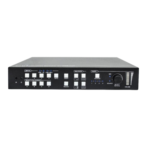
Milestone MP-SC-5D User manual

MP-SC-5D
Compact Scaler Switcher
All Rights Reserved
Version: MP-SC-5D_2016V1.0
User Manual

Compact Scaler Switcher
Safety Operation Guide
In order to guarantee the reliable operation of the equipment and safety of the staff,
please abide by the following proceeding in installation, using and maintenance:
1) The system must be earthed properly. Please do not use two blades plugs and
ensure the alternating power supply ranged from 100v to 240v and from 50Hz to
60Hz.
2) Do not put the device in a place of too hot or too cold.
3) As the power generating heat when running, the working environment should be
maintained fine ventilation, in case of damage caused by overheat.
4) Cut off the general power switch in humid weather or left unused for long time.
5) Before following operation, ensure that the alternating current wire is pull out of the
power supply:
Take off or reship any components of the equipment.
Take off or rejoin any pin or other link of the equipment.
6) As to non-professional or without permission, please DO NOT try to open the
casing of the equipment, DO NOT repair it on your own, in case of accident or
increasing the damage of the equipment.
7) DO NOT splash any chemistry substance or liquid in the equipment or around.

Compact Scaler Switcher
Table of Contents
1. Introduction.................................................................................................................1
1.1 Introduction to MP-SC-5D..................................................................................1
1.2 Features ............................................................................................................1
1.3 Package Contents.............................................................................................1
2. Product Appearance of MP-SC-5D.............................................................................2
2.1 Front Panel........................................................................................................2
2.2 Rear Panel.........................................................................................................3
3. System Connection.....................................................................................................4
3.1 Usage Precautions............................................................................................4
3.2 System Diagram................................................................................................5
3.3 Connection Procedure.......................................................................................5
3.4 Connection of Microphone.................................................................................5
3.5 Application.........................................................................................................7
4. System Operations .....................................................................................................7
4.1 Operations of Buttons........................................................................................7
4.1.1 Resolution Adjusting................................................................................7
4.1.2 Switching Operations...............................................................................8
4.1.3 Software Updating...................................................................................9
4.1.4 Volume Adjusting.....................................................................................9
4.1.5 Operations in OSD Menus.......................................................................9
4.2 Operations of IR ..............................................................................................10
4.2.1 IR Remote .............................................................................................10
4.3 Operations of CEC Function............................................................................11
4.4 Operations of RS232 Control...........................................................................11
4.4.1 Installation/ uninstallation of RS232 Control Software...........................12
4.4.2 Basic Settings........................................................................................12
4.4.3 RS232 Communication Commands ......................................................13
4.5 Operations in OSD Menu.................................................................................20
4.5.1 Option....................................................................................................20
4.5.2 Picture ...................................................................................................22
4.5.3 Sound....................................................................................................23
Compact Scaler Switcher
4.5.4 Setup.....................................................................................................23
4.6 Instructions of VGA Converting Cable .............................................................24
5. Specification .............................................................................................................26
6. Panel Drawing ..........................................................................................................27
7. Troubleshooting & Maintenance ...............................................................................28
8. After-sales Service....................................................................................................30

Compact Scaler Switcher
1
1. Introduction
1.1 Introduction to MP-SC-5D
MP-SC-5D is a compact mini scaler switcher with 5 video inputs (3 HDMI, 2 VGA) and 6
audio inputs (3 HDMI audio & 2 VGA audio: switched following the video; 1 MIC audio
input). As the VGAinput supports VGA, YPbPr and C-video, so the scaler switcher is
compliant with multiple video signals.
MP-SC-5D scales & switches any video signal to HDMI output. MP-SC-5D supports
various control methods including front panel control, IR control and RS232 command
control.
1.2 Features
Compliant with HDCP.
Supports CEC, with commands to enable/disable this function.
Supports video source auto-switching function.
Output resolutions selectable to assure preferred output, and supports various
output resolutions, such as 1920x1200, 1920x1080, 1600x1200, 1360x768,
1280x800, 1280x720, 1024x768.
VGA video supports C-video, YPbPr and VGA.
Supports online software upgrading.
48V phantom power to support condenser microphone.
MIC port supports balance/unbalance signal, suppress the external noise effectively.
3-level MIC inputs, supports condenser microphone, dynamic microphone and
wireless microphone.
Controllable via button, IR & RS232.
Powerful OSD operations.
1.3 Package Contents
1 x MP-SC-5D
2 x Mounting ears (separate from MP-SC-5D)
8 x Screws (for mounting ears)
7 x Captive screw connectors
2 x VGA to YPbPr cables
1 x IR receiver
1 x RS232 cable
4 x Plastic cushions

Compact Scaler Switcher
2
1 x Power Adapter (DC 12V)
1 x IR remote
1 x Warranty Card
1 x Conformity Certificate
1 x User Manual
Notes:Please confirm if the product and the accessories are all included, if not, please
contact with the dealers.
2. Product Appearance of MP-SC-5D
2.1 Front Panel
①Power indicator
Turn red when power on, turn green when in standby mode.
②LCD screen
Show the real-time system working status.
③SOURCE/AUTO
Use as video source selection button, press to select one source, press again to
select next source, switching circularly between HDMI1, HDMI2, HDMI3, VGA1
and VGA2. The LCD screen will show the name of selected source.
Use as switching mode selection button, press and hold on for 7 seconds or
more to enter in Auto-switching mode, press and hold on for 7 seconds or more
again to enter in Manual-switching mode.
Note: Setting any VGA port to AV or YPbPr in Manual-switching mode, the system will
not be able to enter in Auto-switching mode. While in Auto-switching mode, setting any
VGA port toAV or YPbPr will force the system to enter in Manual-switching mode with
LCD screen and RS232 control software prompting “Not support!”.
④ENTER
Press to confirm selection in menu.
⑤RESO/AUTO
RESO / AUTO
SOURCE / AUTO
MENU
ENTER
MENU
VOL - VOL +
SYSTEM MONITOR
MP-SC-5D
FW UPDATE
MIC +
MIC -
① ② ③ ④
⑤ ⑥ ⑦ ⑧⑨
⑩

Compact Scaler Switcher
3
Manual-switching mode: Press this button to select the resolution of HDMI output
manually. The resolution can be selected among 1360x768, 1280x800,
1280x720, 1024x768, 1920x1200, 1920x1080 and 1600x1200.
Auto-switching mode: Press and hold this button for 7 seconds or more to enter
this mode. This Scalar Switcher will automatically select the highest resolution of
HDMI display device.
Press and hold for 7 seconds or more again can back to Manual-switching mode.
⑥MENU/FWUPDATE
Use as menu button, press it to enter in OSD menu.
Use as software updating button, press and hold on for 7 seconds or more to
enter in software updating procedure.
⑦VOL-
Volume down button, press it to turn down the volume
Use as direction button NEXT when in menus.
⑧MIC+
MIC volume up button, press it to turn up the volume of the microphone.
Use as direction button MOVE UP when in menus.
⑨VOL+
Volume up button, press it to turn up the volume.
Use as direction button PREVIOUS when in menus.
⑩MIC-
MIC volume down button, press it to turn down the volume of the microphone.
Use as direction button MOVE DOWN when in menus.
2.2 Rear Panel
①AUDIO INPUT
Including 3 HDMI audio & 2 VGAaudio inputs corresponding to the 5 video inputs,
OUTPUTVIDEO INPUT VGA 2
RS232FIRMWARE
HDMI 1
AUDIO INPUT VGA 2
HDMI 1 HDMI 2 HDMI 3
HDMI 2
OUTPUT
RL
HDMI 3 VGA 1
VGA 1
Tx Rx
AUDIO
RL RL RL RL RL
5-input Scaler Switcher
IR EYE
MIC MIC
48V LINE
⑧ ⑨
ab
⑦
① ② ③ ④ ⑤ ⑥

Compact Scaler Switcher
4
users can choose any one audio (embedded HDMI audio or external input audio) for
HDMI audio input by sending RS232 commands.
②AUDIO OUTPUT
1 Audio output port, connect with an amplifier. The audio comes from the input audio
corresponding to the selected video source and mixed with MIC audio.
③IR EYE
Connect with an IR receiver to receive IR signal sent by the IR remote.
④FIRMWARE
USB port, connect with USB flash disk or other storage with update file to update the
system firmware.
⑤RS232
Serial control port, 3p captive screw connector, connect with a control device (such
as a computer) to control MP-SC-5D.
⑥12V DC
Power port, connect with the 12V DC power adapter.
⑦MIC
a) MIC port, connect with microphone
b) MIC Dial switch: 3 levels: 48V phantom power mode (connect with condenser
microphone), MIC mode (connect with dynamic microphone) and LINE mode
(connect with wireless microphone or line audio).
⑧VIDEO INPUT
Video input ports, includes 3 HDMI inputs & 2 VGAinputs. VGAports support YPbPr,
C-video and VGA format. Factory default is VGA format.
⑨OUTPUT
1 HDMI local output, connect with a HDMI displayer.
3. System Connection
3.1 Usage Precautions
1) System should be installed in a clean environment and has a prop temperature and
humidity.
2) All of the power switches, plugs, sockets and power cords should be insulated and
safe.
3) All devices should be connected before power on.

Compact Scaler Switcher
5
3.2 System Diagram
3.3 Connection Procedure
Step1.Connect HDMI source devices (e.g. Blue-ray DVD) to HDMI input ports of
MP-SC-5D with HDMI cable. Connect VGA source devices (e.g. PC) to VGA
input ports of MP-SC-5D with VGA cable.
Step2.Connect the corresponding audio source to the corresponding AUDIO INPUT
port of MP-SC-5D with audio cable accordingly. The audio of HDMI can be set as
embedded or external by sending right commands.
Step3.Connect a HDMI display device to HDMI output port of MP-SC-5D with HDMI
cable.
Step4.Connect speakers, headphones or amplifiers to AUDIO OUTPUT port of
MP-SC-5D.
Step5.Connect control device (e.g. PC) to the RS232 port of MP-SC-5D.
Step6.Select MIC level and connect right microphone to the MIC input port. MIC audio
will be transmitted to AUDIO OUTPUT port and mixed with source audio.
Step7.Connect DC12V power adaptor to the power port.
3.4 Connection of Microphone
MP-SC-5D provides one 3-level microphone input to accommodate different microphone
input modes, including 48V phantom power mode, MIC mode & LINE mode.
48V phantom power input
When switch to “48V” (It has a good frequency characteristic, high input impedance and
high sensitivity in this mode), the MIC input will offer a 48V phantom power. This is only
used for condenser microphone.
Connect the microphone this way: “+” connects to positive, “-” connects to negative and
DVD
Rs232
control panel
PC
HDTV
DV Camera
PC
Laptop
MIC
Projector

Compact Scaler Switcher
6
“ ” to ground.
MIC input
When switch to “MIC” (It has a low frequency characteristics, and wide frequency
response in this mode), the microphone input is used for connecting with dynamic
microphone. There are two different connections:
1) Unbalanced connection:
“+” and “ ” connect to ground, and “-” connects to signal.
“-”and “ ” connect to ground, and “+” connects to signal.
2) Balanced connection:
“+” connects to positive, “-” connects to negative and “ ” connects to ground.
LINE input
When switch to “LINE” (It has a low frequency characteristics, and wide frequency

Compact Scaler Switcher
7
response in this mode), the microphone input is used for connecting with line audio or
wireless microphone output. There are two different connections:
1) Unbalanced connection:
“+” and “ ” connect to ground, and “-” connects to signal.
“-”and “ ” connect to ground, and “+” connects to signal.
b) Balanced connection:
“+” connects to positive, “-” connects to negative and “ ” connects to ground.
3.5 Application
MP-SC-5D has a good application in various occasions, such as computer realm,
monitoring, conference room, big screen displaying, television education, command &
control center and smart house etc.
4. System Operations
4.1 Operations of Buttons
The buttons can be used for output resolution adjusting, switching operations, software
updating, volume adjusting and operations in menus.
4.1.1 Resolution Adjusting
Support auto-adjusting and manual-adjusting. Press and hold on RESO/AUTO button
for 7 seconds or more to enter in auto-adjusting/manual-adjusting mode.
Notice:

Compact Scaler Switcher
8
1. In auto-adjusting mode, MP-SC-5D will choose the resolution of the display device as
the preferred resolution.
2. In auto-switching mode, front panel button control is not available, but IR and RS232
control is able to switch modes.
4.1.2 Switching Operations
Support auto-switching and manual-switching. Press and hold on SOURCE/AUTO
button for 7 seconds or more to enter in auto-switching/manual-switching mode.
The display result is showed as below:
The display result will be showed for 2 seconds.
The auto-switching mode follows the listed principles:
New input principle
Once detecting a new input signal, MP-SC-5D would switch to this new signal
automatically.
Power rebooting principle
MP-SC-5D offers the function to remember the signal last displayed when rebooting.
Once rebooting, MP-SC-5D will automatically enter in auto-switching mode, and
then detect all inputs and memorize their connection status for future rebooting
using.
And if the signal last displayed is still available, then MP-SC-5D will output the signal.
If not, there will be no signal on outputs.
Signal removing principle
Once removing the current display signal, MP-SC-5D will detect all input signals with
priority (from INPUT 1 to INPUT 5). It will output the signal firstly detected to be
available.
Notice: Auto-switching function works only when there is new input signal, or when
users remove a signal or power rebooting. With any VGAport set to AV or YPbPr, the
system will be not able to enter in Auto-switching mode.
Operation Examples:
Connect the INPUT 2, INPUT 4, and INPUT 5 ports to the source devices, select
INPUT 4 to outputs.
Press and hold on the front key SOURCE/AUTO for 7 seconds or more to enter in
IN: HDMI1 AUTO
1280 X 720
IN: HDMI1 MANUAL
1280 X 720
Auto-switching function

Compact Scaler Switcher
9
auto-switching mode.
With no signal removing or new input, MP-SC-5D just works in auto-switching mode,
and take no action (Output from INPUT 4).
Connect INPUT 3 with a source device, and then it will choose INPUT 3 to output.
Remove the signal of INPUT 3, MP-SC-5D will detect from INPUT 1 to INPUT 5. And
when it detects that input 2 is available, it will choose INPUT 2 to output.
Cut off the power of MP-SC-5D, then reboot.As MP-SC-5D is in auto-switching
mode, then it will choose INPUT 2 to output.
4.1.3 Software Updating
Software updating means to update the inside program of this scaler switcher.
MP-SC-5D supports software updating via USB flash disk. The Operation is:
1) Copy the file “MERGE_51D.bin” to the root directory of a USB flash disk. (Make sure
the file is copied to the root directory for normal use.
2) Plug the USB flash disk to the MP-SC-5D USB port on its front panel.
3) Press the button “MENU” for 7 seconds or more to update the software
automatically.
Or press this button for 1 second to open the OSD menu “Option”Select
“Software Update” to enter in update procedure.
Or send command 50698%to update software.
4.1.4 Volume Adjusting
Not in OSD menu, press VOL -- to decrease line volume, VOL + to increase.
Not in OSD menu, press MIC –to decrease MIC volume, MIC + to increase.
4.1.5 Operations in OSD Menus
Press MENU button to enter in the OSD menu, and use UP, DWON, LEFT, RIGHT
button to select, press ENTER button to confirm selection. MENU button also can be
used to exit present menu level by level until exiting the OSD menu.

Compact Scaler Switcher
10
4.2 Operations of IR
4.2.1 IR Remote
With its CEC function, users are able to control the MP-SC-5D and source devices
synchronously via one IR remote.
①Standby button
To enter in/ exit standby mode.
②Input channel selection buttons
INPUT 1 is for HDMI1, INPUT 2 for
HDMI2…INPUT 5 for VGA2. AUTO button:
Enable/disable auto-switching mode.
③Volume adjusting buttons
MIC-/+: decrease/increase MIC volume
LINE-/+: decrease/increase line volume
MIC MUTE: mute/unmute MIC audio
LINE MUTE: mute/unmute line audio
④Menu operation buttons
MENU: press to enter in OSD menu or used to
return to previous menu. EXIT: exit OSD menu.
OK: confirm button. Navigation buttons:
UP/DWON/LEFT/ RIGHT button, for value setting
or page-turn, Buttons in area a are also able to
work in CEC mode to enter the menu of HDMI
source device. P.P, ZOOM, S.M: shortcut button,
to select display mode.
⑤Resolution selection buttons
Select the resolution by pressing corresponding
button. AUTO is for auto-selecting the best
resolution.
⑥CEC function buttons
These are for HDMI input signal which supports
CEC. Include PLAY, PAUSE, STOP, MENU, REV
(reverse) and FWD (forward).
Buttons in section a work when entered CEC too.

Compact Scaler Switcher
11
4.3 Operations of CEC Function
MP-SC-5D supports CEC and CEC standby functions, and can be enabled/ disabled
through RS232 commands or OSD menu. If the HDMI source device supports CEC and
its CEC is on, and when MP-SC-5D enter in standby/startup mode, then source device
will automatically enter in standby/startup mode.
And due to CEC function, user can control HDMI source device with basic operations
(play, pause, fast forward, fast reverse, menu etc.). So user is able to control MP-SC-5D
and HDMI source device via the IR remote of MP-SC-5D.
Commands for CEC function: “50686%”(enable CEC) and “50687%”(disable CEC).
The working status related to CEC and STANDBY is showed as below:
Situation
Working Status
CEC: on, Standby: on
Press STANDBY button on IR remote, MP-SC-5D enters in
standby mode, so do all HDMI source devices.
Press STANDBY button again on IR remote, MP-SC-5D exits
standby mode, only the HDMI source device switched to
starts working.
CEC: on, Standby: off
Press STANDBY button on IR remote, MP-SC-5D enters in
standby mode, HDMI 1~3 source devices keep on.
CEC: on
Use CEC function buttons, ▲,▼, , and OK buttons on
IR remote to control HDMI source devices, include play,
pause, fast forward, fast reverse and operations in menu.
CEC: off
Unable to control HDMI source devices through IR remote.
CEC: Control HDMI source devices by IR remote of MP-SC-5D
4.4 Operations of RS232 Control
MP-SC-5D can be controlled by sending RS232 commands. Connect the RS232 port of

Compact Scaler Switcher
12
MP-SC-5D and the RS232 port of control device (e.g. a PC). Install the RS232 control
software to the control device, then users are able to control the MP-SC-5D by sending
RS232 commands. Here is an operation guidance for RS232 control.
4.4.1 Installation/ uninstallation of RS232 Control Software
Installation Copy the control software file to the computer connected with
MP-SC-5D.
Uninstallation Delete all the control software files in corresponding file path.
4.4.2 Basic Settings
First to connect MP-SC-5D with all input devices and output devices needed, then to
connect it with a computer which is installed with RS232 control software. Double-click
the software icon to run this software.
Here we take the software CommWatch.exe as example. The icon is showed as below:
The interface of the control software is showed as below:

Compact Scaler Switcher
13
Please set the parameters of COM number, bound rate, data bit, stop bit and the parity
bit correctly, and then you are able to send commands in Command Sending Area.
4.4.3 RS232 Communication Commands
Communication protocol: RS232 Communication Protocol.
Baud rate: 9600 Data bit: 8 Stop bit: 1 Parity bit: none
Command
Function
Feedback Example
Switch Commands
50701%
Switch to HDMI 1 input
Switch to HDMI 1
50702%
Switch to HDMI 2 input
Switch to HDMI 2
50703%
Switch to HDMI 3 input
Switch to HDMI 3
50704%
Switch to VGA 1/YPbPr 1/AV 1 input
Switch to VGA 1/YPbPr 1/AV 1
50705%
Switch to VGA 2/YPbPr 2/AV 2 input
Switch to VGA 2/YPbPr 2/AV 2
50680%
Select VGA 1 for INPUT 4
Input 4 Set & Switch to VGA 1
50681%
Select YPbPr 1 for INPUT 4
Input 4 Set & Switch to AV 1
Parameter Configuration area
Monitoring area, indicates
whether the command sent
works.
Command Sending area

Compact Scaler Switcher
14
Command
Function
Feedback Example
50682%
Select AV 1 for INPUT 4
Input 4 Set & Switch to AV 1
50683%
Select VGA 2 for INPUT 5
Input 5 Set & Switch to VGA 2
50684%
Select YPbPr 2 for INPUT 5
Input 5 Set & Switch to YPbPr 2
50685%
Select AV 2 for INPUT 5
Input 5 Set & Switch to AV 2
50785%
Enable auto-switching
Auto Switching
50786%
Disable auto-switching
Manual Switching
Audio Commands
50600%
MUTE line audio
LINE Mute
50601%
UnMute line audio
LINE Unmute
50602%
Line audio volume up
LINE Volume: xx
50603%
Line audio volume down
LINE Volume: xx
50720%
Mute LINE audio & MIC audio
LINE Mute
MIC Mute
50721%
Unmute LINE audio & MIC audio
LINE Unmute
MIC Unmute
50722%
Mute MIC audio
MIC Mute
50723%
Unmute MIC audio
MIC Unmute
50694%
Enable Mic precedence
Mic precedence: enable
图像输出调整关闭
Exit Output Position Adjust
50695%
Disable Mic precedence
Mic precedence: disable
图像整体向右移动
Output Position Adjust X xx
50696%
Check Mic precedence status
Mic precedence: XXXX
图像整体向左移动
Output Position Adjust X xx
50724%
MIC volume up
MIC Volume: xx
50725%
MIC volume down
MIC Volume: xx
508xx%
Set MIC volume
MIC Volume: xx
50706%
Choose embedded audio as HDMI 1
audio input
HDMI 1 Audio from Embedded
50707%
Choose external audio as HDMI 1
audio input
HDMI 1 Audio from LINE
50708%
Choose embedded audio as HDMI 2
audio input
HDMI 2 Audio from Embedded
50709%
Choose external audio as HDMI 2
HDMI 2 Audio from LINE

Compact Scaler Switcher
15
Command
Function
Feedback Example
audio input
50710%
Choose embedded audio as HDMI 3
audio input
HDMI 3 Audio from Embedded
50711%
Choose external audio as HDMI 3
audio input
HDMI 3 Audio from LINE
Resolution Commands
50619%
Change the resolution to 1360X768
HD
Resolution: 1360x768
50626%
Change the resolution to 1024X768
XGA
Resolution: 1024x768
50627%
Change the resolution to 1280X720
720P
Resolution: 1280x720
50628%
Change the resolution to 1280X800
WXGA
Resolution: 1280x800
50629%
Change the resolution to 1920X1080
1080P
Resolution: 1920x1080
50620%
Change the resolution to1920X1200
WUXGA
Resolution: 1920x1200
50621%
Change the resolution to1600X1200
UXGA
Resolution: 1600x1200
Setup Commands
50604%
Lock the front panel buttons
Front Panel lock
50605%
Unlock the front panel buttons
Front Panel Unlock
501xx%
Set the volume to xx. XX ranges from
0 to 60
LINE Volume: xx
502xx%
Set the brightness to xx. XX ranges
from 0 to 99
Brightness: xx
503xx%
Set the contrast to xx. XX ranges from
0 to 99
Contrast: xx

Compact Scaler Switcher
16
Command
Function
Feedback Example
504xx%
Set the saturation to xx. XX ranges
from 0 to 99
Saturation: xx
505xx%
Set the sharpness to xx. XX ranges
from 0 to 99
Sharpness: xx
50607%
Adjust the color temperature
Color Temperature: xx
50608%
Set the aspect ratio
Aspect Ratio: xx
50614%
Set the picture mode
Picture Mode: xx
50615%
Set SM audio mode
Sound Mode: xx
50655%
Freeze output image
Freeze: enable
50656%
Cancel the freezing of output image
Freeze: disable
50646%
Enable MIC Volume Icon display
Volume Icon: enable
50647%
Disable MIC Volume Icon display
Volume Icon: disable
50648%
Enable HDMI embedded audio output
Embedded Audio Output: enable
50649%
Disable HDMI embedded audio
output
Embedded Audio Output: disable
50761%
Not display mute icon of LINE audio
LINE Mute Icon: disable
50762%
Display mute icon of LINE audio
LINE Mute Icon: enable
50763%
Not display mute icon of MIC audio
MIC Mute Icon: disable
50764%
Display mute icon of MIC audio
MIC Mute Icon: enable
50765%
Display freeze icon
Freeze Icon: enable
50766%
Not display freeze icon
Freeze Icon: disable
50644%
Display channel status
Input Icon: enable
50645%
Not display channel status
Input Icon: disable
50650%
Check the channel status
Input Icon: xx
50606%
Auto-adjust the input parameter(VGA
only)
VGA Input Auto
50699%
Check the system version
Version Vx.x.x
50688%
Enable MIC noise detecting
MIC detect: enable
50689%
Disable MIC noise detecting
MIC detect: disable
50690%
Check MIC noise detecting statue
MIC detect: XXXX
Table of contents
Other Milestone Switch manuals

Milestone
Milestone ML 102 AUDIO VIDEO User manual

Milestone
Milestone ML 201 KVM SS User manual

Milestone
Milestone ML 201 KVM SS User manual

Milestone
Milestone ML 202 VA User manual

Milestone
Milestone ML 44PSS User manual

Milestone
Milestone ML440PS User manual

Milestone
Milestone ML 201 XGA User manual

Milestone
Milestone PRO MP-SC6T-MV User manual

Milestone
Milestone MP-3113-BI User manual

Milestone
Milestone ML 401 VIDEO User manual