Simon Beta Test 7/9/01 User manual

Contents
6LPRQ6HFXULW\
6\VWHP&RQWURO
3DQHO
Installation Instructions
Document Number: 466-1873 BETA TEST
June 2001
Beta Test 7/9/01
Test Weekly
C O D E
Status
System
9 / 0
Windows
Doors & Sensors
Motion
Disarm
5 / 6
Arm
3 / 4 7 / 8
On Off
AUX
SensorMotion Time
FIRE POLICE
Lights
Special
H O M E C O N T R O L
E M E R G E N C Y
H O M E S E C U R I T Y
Doors
Chime
1 / 2
ITI Part No. 60-875-95R
Introduction 1
System Components 1
Control Panel 1
System Devices 1
Planning Sensor Types & Locations 2
Control Locations 2
Control Panel 2
Remote Handheld Touchpad 3
Keychain Touchpad 3
Lamp, Appliance, Wallswitch, and Universal Module
Control 3
House Code and Unit Numbers 3
Installing the System 4
Materials Needed 4
Mounting the Panel 4
Hardwire Interior Sirens 4
Hardwire Exterior Siren 5
Hardwire Sensors 5
Antenna 5
Universal Module 5
Power Transformer 5
Backup Battery 6
Phone Line Connections 6
Full Line Seizure with an RJ-31X 6
Full Line Seizure with an RJ-11 6
Sensor Installation 6
Programming 7
Closing the Cover 7
Reset Memory to the Factory Defaults 8
Set the Clock 8
Adding (Learning) Sensors 8
Deleting Sensors 9
Light and Appliance Controls 9
Numbered Options 9
Option 01: Panel Piezo Beeps 10
Option 02: Panel Voice 10
Option 03: Latchkey 10
Option 04: Primary Phone Number 10
Option 05: Secondary Phone Number 10
Option 06: Downloader Phone Number 11
Option 07: Account Number 11
Option 08: Phone Lock 11
Option 09: Downloader Code 11
Option 10: Entry Delay 11
Option 11: Exit Delay 11
Option 12: Phone Mod 1 12
Option 13: Phone Mod 2 12
Option 14: DTMF Dialing 12
Option 15: No Activity Time-out 12
Option 16: Auto Phone Test 12
Option 17: Dialer Delay 12
Option 18: Alarm Cancel Report 13
Option 19: RF Timeout 13
Option 20: Manual Phone Test 13
Option 21: Opening Reports 13
Option 22: Closing Reports 13
Option 23: Force Armed Report 13
Option 24: AC Power Failure Report 14
Option 25: CPU Low Battery Report 14
Option 26: Fail to Communicate 14
Option 27: Ring/Hang/Ring 14
Option 28: No Delay from Keychain Touchpad 14
Option 29: Panel Piezo Alarms 14
Option 30: Panel Panic Alarms 15
Option 31: Downloader Enable 15
Option 32: 300 Baud 15
Option 33: Audio Verification 15
Option 34: Fail to Open Report 15
Option 35: Fail to Close Report 15
Option 36: Sensor Activated Light Lockout Start
Time 15
Option 37: Sensor Activated Light Lockout Stop
Time 15
Option 38: Auto Arm 16
Option 39: Siren Time-out 16
Option 40: Trouble Beeps 16
Option 41: Chime Voice 16
Option 42: Speaker Level 16
Option 43: Pager Phone Number 16
Option 44: Pager Phone Mod 3 17
Option 45: Sensor Alarm Restoral Report 17
Option 46: Fire Shutdown - AVM 17
Option 47: AVM Mode 17
Option 48: Panic Talk - AVM 17
Option 49: Arming LEDs Shutdown 17
Option 50: RF Jam Detect 17
Option 51: 24 Hour Tamper 17
Option 52: Unvacated Premises 18
Option 53: Hardwire Siren Supervision 18
Option 54: Access Code Length 18
Option 55: Status Beep Volume 18
Option 56: Call Waiting 18

i
Beta Test 7/9/01
Option 57: Supervisory/Tamper Report 18
Option 58: Remote Touchpad Arming 18
Option 60: Secure Arming 19
Option 61: Demo Mode 19
Option 62: Supervisory Protest 19
Option 63: 24 Hour Time 19
Option 64: No Arm on Panel Low Battery 19
Option 65: No Usage Report 19
Option 66: External Siren Delay 19
Option 67: Quick Exit 19
Option 69: SIA Limits 20
Option 70: Line Cut Detection 20
Option 71: Programming Report 20
Option 72: Supervisory Time 20
Option 73: Modem Sensitivity 20
Option 74: Silent Panel Police Panic 20
Option 75: VOX Mic Gain 20
Option 76: VOX Gain Range 21
Option 77: Manual Mic Gain 21
Option 78: VOX Receiver Gain 21
System Access Codes 21
Testing the System 22
Control Panel 22
Testing Sensors 22
Phone Communication 24
Central Station Communication 25
Pager Communication 25
Testing 2-Way Voice Operation 25
X-10 Lamp Modules 26
Siren and X-10 Lamp Module Functions 26
Emergency Planning 26
Specifications 27
Appendix A: Troubleshooting 28
Appendix B: Options 30
Appendix C: Planning Tables 35
Appendix A: Troubleshooting 28
Appendix B: Options 30
Appendix C: Planning Tables 35

FCC Notices
FCC Part 15 Information to the User
Changes or modifications not expressly approved by Interlogix Inc. can void the user’s authority to operate the equipment.
FCC Part 15 Class B
This equipment has been tested and found to comply with the limits for a Class B digital device, pursuant to part 15 of the FCC Rules. These
limits are designed to provide reasonable protection against interference in a residential installation.
This equipment generates, uses, and can radiate radio frequency energy and, if not installed and used in accordance with the instructions,
may cause harmful interference to radio communications. However, there is no guarantee that interference will not occur in a particular
installation.
If this equipment does cause harmful interference to radio or television reception, which can be determined by turning the equipment off and
on, the user is encouraged to try to correct the interference by one or more of the following measures:
❑Reorient or relocate the receiving antenna.
❑Increase the separation between the equipment and receiver.
❑Connect the affected equipment and the panel receiver to separate outlets, on different branch circuits.
❑Consult the dealer or an experienced radio/TV technician for help.
FCC Part 68
This equipment complies with Part 68 of the FCC Rules. Located on this equipment is a label that contains, among other information, the
FCC registration number and the ringer equivalence number (REN) for this equipment. If requested, this information must be provided to the
telephone company.
The REN is used to determine the maximum number of devices that may be connected to your telephone line. In most areas, the sum of all
device RENs should not exceed five (5.0).
If this equipment causes harm to the telephone network, the telephone company may temporarily disconnect your service. If possible, you
will be notified in advance. When advance notice is not practical, you will be notified as soon as possible. You will also be advised of your
right to file a complaint with the FCC.
Your telephone company may make changes in its facilities, equipment, operations, or procedures that could affect the proper operation of
your equipment. You will be given advanced notice in order to maintain uninterrupted service.
If you experience trouble with this equipment, please contact the company that installed the equipment for service and repair information.
The telephone company may ask you to disconnect this equipment from the network until the problem has been corrected or you are sure
that the equipment is not malfunctioning.
This equipment may not be used on coin service provided by the telephone company. Connection to party lines is subject to state tariffs.
Beta Test 7/9/01

Beta Test
Canada Notice
The Canadian Department of Communications label identifies certified equipment. This certification means that the equipment meets certain telecommuni-
cations network protective, operational, and safety requirements. The department does not guarantee the equipment will operate to the user’s satisfaction.
Before installing this equipment, users should ensure that it is permissible to be connected to the facilities of the local telecommunications company. The
equipment must also be installed using an acceptable method of connection. In some cases, the company’s inside wiring associated with a single-line indi-
vidual service may be extended by means of a certified connector assembly (telephone extension cord). The customer should be aware that compliance with
the above conditions may not prevent degradation of service in some situations.
Repairs to certified equipment should be made by an authorized Canadian maintenance facility designated by the supplier. Any repairs or alterations made
by the user to this equipment, or equipment malfunctions, may give the telecommunications company cause to request the user to disconnect the equipment.
For your protection, make sure that the electrical ground connections of the power utility, telephone lines, and internal metallic water pipe system, if present,
are connected together.
&$87,21
Do not attempt to make connections yourself. Contact the appropriate electrician or electric inspections authority.
The Load Number (LN) assigned to each terminal device denotes the percentage of the total load to be connected to a telephone loop which is used by the
device, to prevent overloading. The termination on a loop may consist of any combination of devices subject only to the requirement that the total of the
LNs of all the devices does not exceed 100. Load Number: _____________ Acceptability Number: ____________
“AVIS: - L ´étiquette du ministère des Communications du Canada identifie le matériel homologué. Cette étiquette certifie que le matériel est conforme a
certaines normes de protection, d ´exploitation et de sécuritédes réseaux de télécommunications. Le ministère n ´assure toutefois pas que le matériel fonc-
tionnera a la satisfaction de l ´utilisateur.
Avant d ´installer ce matériel, l ´utilisateur doit s ´assurer qu´il est permis de le raccorder aux installations de l ´enterprise locale de télécommunication.
Le matériel doit également etre installéen suivant une méthod acceptée de raccordement. Dans certains cas, les fils intérieurs de l´enterprise utilisés pour
un service individuel a ligne unique peuvent etre prolongés au moyen d´un dispositif homologuéde raccordement (cordon prolongateur téléphonique
interne). L ´abonnéne doit pas oublier qu ´il est possible que la conformitéaux conditions énoncées ci-dessus n ´empechent pas le dégradation du service
dans certaines situations. Actuellement, les enterprises de télécommunication ne permettent pas que l ´on raccorde leur matériel a des jacks d ´abonné, sauf
dans les cas précis prévus pas les tarrifs particuliers de ces enterprises.
Les réparations de matériel homologuédoivent etre effectuées pas un centre d ´entretien canadien autorisédésignépar le fournisseur. La compagne de télé-
communications peut demander a l ´utilisateur de débrancher un appareil a la suite de réparations ou de modifications effectuées par l ´utilisateur ou a
cause de mauvais fonctionnement.
Pour sa propre protection, l ´utilisateur doit s ´assurer que tous les fils de mise a la terre de la source d ´énergie électrique, des lignes téléphoniques et des
canalisations d ´´ eau métalliques, s ´il y en a, sont raccordés ensemble. Cette précaution est particulièrement importante dans les régions rurales.
Avertissment. - L ´utilisateur ne doit pas tenter de faire ces raccordements lui-meme; il doit avoir recours a un service d ´inspection des installations élec-
triques, ou a electricien, selon le cas”.
Une note explicative sur les indices de charge (voir 1.6) et leur emploi, a l ´intention des utilisateurs du matériel terminal, doit etre incluse dans l ´informa-
tion qui accompagne le materiel homologué. La note pourrait etre rédigée selon le modèle suivant:
“L ´indice de charge (IC) assignéa chaque dispositif terminal indique, pour éviter toute surcharge, le pourcentage de la charge totale qui peut etre raccordée
a un circuit téléphonique boucléutilisépar ce dispositif. La terminaison du circuit bouclépeut etre constituée de n ´import somme des indices de charge de
l ´ensemble des dispositifs ne dépasse pas 100.”
L ´Indice de charge de cet produit est ____________.
2266 Second Street North |North Saint Paul Mn |55109 |800-777-2624 |www.interlogixinc.com
©2001 Interlogix,™ Inc. Interlogix is a trademark of Interlogix, Inc. ITI, Advent, and SuperBus are registered trademarks of Interlogix, Inc.

1
Introduction
Beta Test 7/9/01
Introduction
The system is easy to install if you plan ahead and perform
the installation in the following order:
1. Determine locations for hardwire sirens, sensors, and
the panel. Use the tear out planning sheets at the back
of this manual.
2. Wire the Class II transformer, hardwire sirens, and
phone.
3. Determine sensor, light, and system option operation.
4. Program the sensors, lamp and appliance modules, and
system options.
Note
Program (add) sensors into panel memory before install-
ing them at their permanent location.
5. Install sensors, lamp and appliance modules.
6. Test the system.
Figure 1. Typical Security System Components
System Components
The security system has three types of components: the con-
trol panel, devices that report to the panel, and devices that
respond to commands from the panel.
Control Panel
The control panel is the main processing unit for all system
functions. It receives and responds to signals from wireless
sensors and wireless touchpads throughout the premises.
For monitored systems, the panel can be connected to the
premises phone line for central monitoring station report-
ing.
Two panel models are available. One has an on-board 2-
way voice microphone, the other does not. The Interroga-
tor®200 Audio Verification Module can be added to either
panel.
User Interface
When the panel cover is closed, the panel buttons operate
the security system. When the panel cover is open, the but-
tons program the security system.
Operation
The user operates the panel by pressing panel buttons or by
using a touchpad. See the User Manual for complete opera-
tion instructions.
Panel Programming
The panel can be programmed on-site by the installer or
user, or from off-site using ITI ToolBox®software. See the
“Programming”section of this manual for complete on-site
programming instructions.See the ITI ToolBox manual and
ToolBox on-line help for off-site programming instructions.
Note
ITI ToolBox has not been investigated by UL and should
not be used to program panels in UL listed systems.
Panel Tamper
If the panel cover is opened while the system is armed, an
intrusion alarm occurs. When the system status button is
subsequently pressed, the panel says System Access Alarm.
System Devices
The system can monitor up to 24 sensors and may use any
of the following:
Door/Window Sensor (60-670)
For intrusion protection, install Door/Window sensors on all
ground-floor doors and windows. At a minimum, install
them in the following locations:
❑All easily accessible exterior doors and windows.
❑Interior doors leading into the garage.
❑Doors to areas containing valuables such as cabinets
and closets.
Indoor Motion Sensor (60-639)
Indoor motion sensors are ideal whenever it is not practical
to install door/window sensors on every opening. Identify
areas where an intruder is likely to walk. Large areas in an
open floor plan, downstairs family rooms, and hallways are
candidates for indoor motion sensors. If pets will be in the
area, use the ITI SAW Pet Immune PIR (60-807). Indoor
motion sensors can also be used to sound chimes, but can-
not be used for intrusion protection and as a chime sensor
simultaneously.
Outdoor Motion Sensor (60-639)
Use outdoor motion sensors to identify motion in a pro-
tected outdoor area. Detected motion in this protected area
can sound chimes or turn on outside lights. Do not use Out-
door Motion Sensors for intrusion protection.
Freeze Sensor (60-742)*
Freeze sensors detect low temperature conditions, which
may indicate a furnace failure. The sensor contains a bime-
tallic thermal switch connected to the built-in transmitter.
The sensor transmits an alarm signal to the panel when the
surrounding temperature drops to about 41°F. When the
X-10 POWERHOUSE
13
5
9
13
711
15 AC
E
I
M
GK
O
UNITCODE HOUSE CODE
CONTINUOUS
MOMENTARY
SOUNDERONLY
SOUNDER& RELAY
RELAYONLY
ON OFF
DOOR/WINDOW
SENSOR
LAMP
MODULE APPLIANCE
MODULE
GARAGE DOOR
MODULE
REMOTE
HANDHELD
TOUCHPAD
MOTION
SENSOR
KEYCHAIN
TOUCHPAD
SMOKE
SENSOR
8988G21Z.EPS
13
5
9
13
7
11
15
AC
E
I
M
GK
O
13
5
9
13
7
11
15
AC
E
I
M
GK
O
7
4
1
89
5
2
6
3
Off
sP
EMERGENCY
On
d&sres Hol hBtoeK y
DISARM
SYSTEM
STATUS
Doors &
Windows
ARM
ARM
Sensors
Motion
-
CARBON
MONOXIDE
DETECTOR
CARBON MONOXIDE
ALARM
TOUCHTALK
2-WAY RF
TOUCHPAD
AUDIO VERIFICATION
MODULE
Test Weekly
C O D E
Status
System
9 / 0
Windows
Doors & Sensors
Motion
Disarm
5 / 6
Arm
3 / 4 7 / 8
On Off
AUX
SensorMotion Time
FIRE POLICE
Lights
Special
H O M E C O N T R O L
E M E R G E N C Y
H O M E S E C U R I T Y
Doors
Chime
1 / 2
FREEZE SENSOR

2
Planning Sensor Types & Locations Beta Test 7/9/01
temperature rises to 50°F, the sensor transmits a restore sig-
nal to the panel.
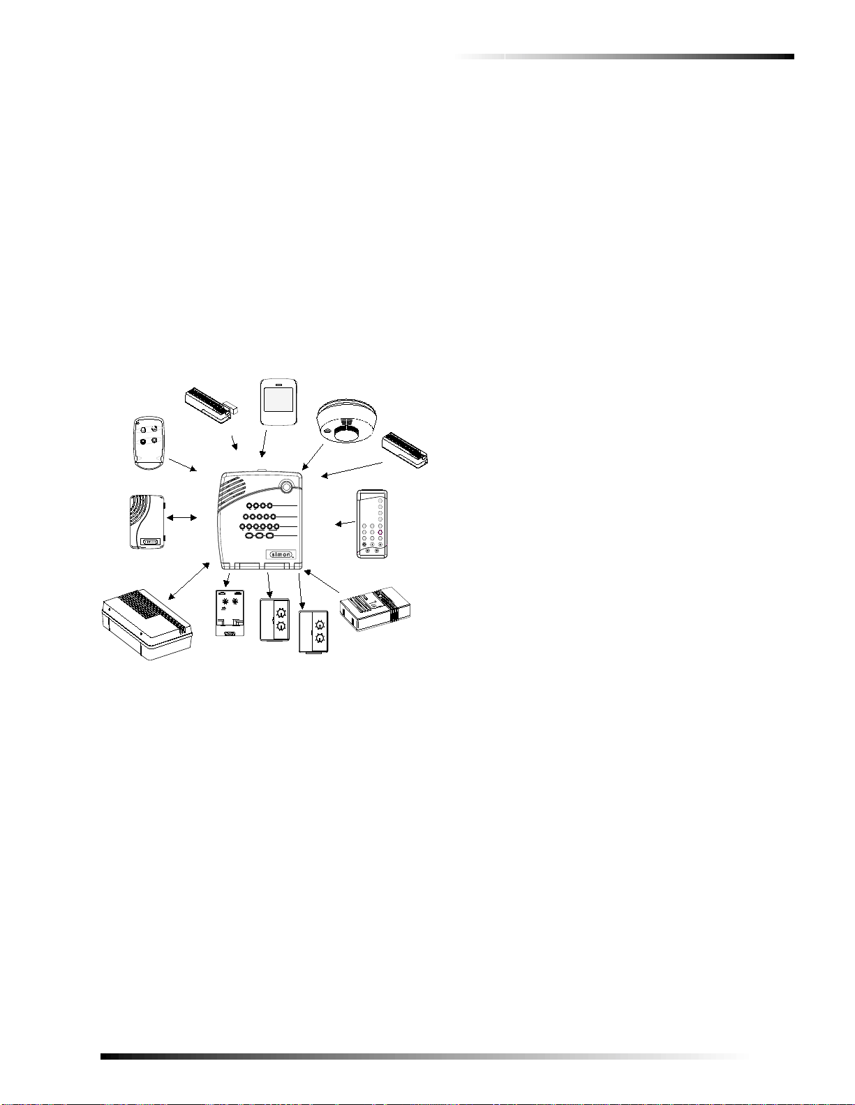
Water Sensor (60-744)*
Water sensors detect a water leak in a home or business.
The detector is connected to the sensor by an 8-foot (2.4-
meter) cable. Water that reaches both detector contact
points activates the sensor, causing it to transmit an alarm
signal.
Smoke Sensor
Smoke sensors can provide fire alert protection by causing
the alarm to sound throughout the house. You can add
smoke sensors near sleeping areas and on every floor of the
house. Avoid areas that could have some smoke or exhaust
such as attics, kitchens, above fireplaces, dusty locations,
garages, and areas with temperature extremes. In these
areas you may want to install Rate-of-Rise sensors to detect
extreme temperature changes. See “Emergency Planning”
on page 26 and the instructions packaged with the smoke
sensor for complete placement information.
Carbon Monoxide (CO) Alarm (60-652-95)*
The Learn Mode™CO Alarm alerts users to hazardous lev-
els of carbon monoxide gas. If dangerous concentrations of
gas are present, the red indicator light comes on, the internal
siren goes off, and an alarm is transmitted to the panel. The
panel sounds its own alarm and calls the central station.
Keychain Touchpad (60-659)
The Keychain Touchpad enables you to turn the system on
and off from right outside the home or to turn on the siren
and to call the central monitoring station if there is an emer-
gency. If you have Lamp Modules, you can use keychain
touchpads to turn all system controlled lights on and off.
Remote Handheld Touchpad (60-671)
The Remote Handheld Touchpad enables you to turn the
system on and off while in the home, turn lights controlled
by the system on and off (all or individual lights), or turn on
a system siren and call the central monitoring station if
there is a non-medical emergency. The Remote Handheld
Touchpad will report an alarm type specific to its sensor
type (see the “Sensor Group Characteristics”on page 33).
X-10 Modules
When the panel is powered using the line carrier power
transformer, the system can work with any of the following
modules:
❑X-10 Appliance Modules (13-402)
❑X-10 Powerhorn/Remote Siren Modules (13-398)
❑X-10 Universal/Garage Door Modules (13-399)
❑X-10 Wall Switch Modules (13-397)
❑Interrogator®200 Audio Verification Module (AVM)
(60-787)
Note
Use of the above X-10 modules has not been investi-
gated by UL.
Interrogator®200 Audio Verification Module (60-677)*
The Audio Verification Module (AVM) gives the central
station operator the ability to hear what’s happening at the
premises during an alarm and to speak directly to the sys-
tem user. The operator can then determine how serious an
alarm is, find out what kind of help is needed, and dispatch
the appropriate assistance. Only one AVM may be installed
per panel.
*) Not investigated by UL
Planning Sensor Types & Locations
The first step to an easy and successful installation is to
decide what areas or items to protect, which lights or appli-
ances to operate, and the best location for the panel, touch-
pad, sensors, and sirens. Use the previous information and
the Table “Recommended Sensor Types”on page 2, to note
your requirements.
Metal objects, mirrors, and metallic wallpaper can block
signals sent by the wireless sensors. Make sure there are no
metal objects in the way when installing the system.
Use the planning tables in Appendix A to determine the
appropriate Sensor Type for the sensors you will be adding.
You’ll need to understand the application for each sensor.
For example, Keychain Touchpads are typically pro-
grammed as sensor type 01 (Portable panic),used to send an
intrusion alarm to a central monitoring station. This sensor
type is instant intrusion, it does not require restoral or super-
visory communication with the panel and it is active in 4
arming levels (disarm, arm doors & windows, arm motion
sensors, and arm doors/windows and motions sensors).
Control Locations
Control Panel
Locate the panel so that the alarm sounds can be heard and
is easily accessible for operation.
Do not install the panel near a window or door where it can
be reached easily by an intruder.
Recommended Sensor Types
Device Recommended
Sensor Type
Keychain Touchpad 01, 03, 06, 07
Remote Handheld Touchpad 01, 03, 06, 07
Indoor Motion Sensor 17 (intrusion), 25
(chime)
Outdoor Motion Sensor 25
Smoke Sensor 26
Exterior Door 10
Interior Door 14
Window Sensor 13
CO Alarm 34
Freeze & Water Sensors 29

3
Planning Sensor Types & Locations
Beta Test 7/9/01
Remote Handheld Touchpad
Locate Remote Handheld Touchpads where they will be
convenient and offer quick access to the user.
Keychain Touchpad
Keychain Touchpads attach to the owner’s key ring or can
be conveniently carried.
Lamp, Appliance, Wallswitch, and
Universal Module Control
The system can control up to 8 individual unit numbers on
Lamp, Wallswitch, Appliance, and Universal Modules.
House Code and Unit Numbers
Each device (lamp, appliance, garage door, etc.) controlled
by the panel must have an identification setting. The mod-
ules use two dials to set identification codes: one with let-
ters A through P and one with numbers 1 through 16.
The lettered dial sets the house code, which enables the sys-
tem to differentiate this home from other homes in the area.
Set all modules (except the remote siren) and the panel to
the same house code.
Note
All Lamp Modules with the same house code will turn on
or flash as a group during an alarm or when operating the
“Light”button on a Keychain Touchpad.
The numbered dial sets the unit number, which identifies
and lets you control a specific device. Each device must
have a unique unit number (1-8) to be individually con-
trolled. For example, lights and appliances operated from a
Remote Handheld Touchpad or operated by a sensor; or
lights programmed to go on during the entry/exit delay or at
scheduled times.
Note
When unit numbers 9-16 are used for lamp modules,
they can only be controlled by an all on or all off com-
mand.
A lamp will flash to the arming level if its unit number is
set to 10. A lamp set to unit number 10 will flash once if
the panel is disarmed, twice if doors & windows are
armed, etc.
The remote siren can be set to any unit number to hear
alarm sounds. Set it to unit number 9 to also hear arming
level beeps, status beeps, and trouble beeps.
Do not use a lamp module to control appliances. Use an
appliance module, since the wattage rating on Lamp
Modules is less than on Appliance Modules.
To Fill Out the Home Control Planning Table:
1. Set the house code on all modules (except the remote
siren) to the same letter.
Note
The house code instructions that come with the Power-
horn Siren won’t work with this panel. Follow the house-
code instructions given here.
2. Set the Remote Siren house code to the next alphabeti-
cal letter. For example, if you chose house code B in
step 1 above, set the remote siren house code to C.
3. Set the module unit numbers.
Note
If you are using a Universal Module to operate a garage
door, make sure to assign a unique unit number to this
module, choosing from 1-8.
4. List the location of the lamp or appliance in the Loca-
tion column of the “Home Control Planning Table*”on
page 34.
5. Write the location of each Lamp Module on an adhe-
sive note and label the module.
6. Decide if the device should be activated by sensors,
entry/exit delay, time, or a combination. An example of
sensor activation is using a motion sensor to turn on a
light. Record the information in the appropriate col-
umns.
Use the following tables to help you further plan X-10 mod-
ule installation.
House Code Assignments
House Codes Results
A through P Set all modules to the same house
code except the remote sirens.
Next Higher House
Code Remote Siren needs must be set to
the next higher alphabetical letter.
Unit # Result
1 - 8 Used for sensor-activated, time-activated,
and entry/exit delay lights.
❑Sensor-activated lights are enabled and
disabled pressing the LIGHTS Sensor
Activated button on the panel.
❑Time-activated lights are enabled and
disabled by pressing the LIGHTS Time
Activated button on the panel.
If using the universal module to operate a
garage door, be sure to assign a unique unit
number.
❑The STAR button on the KeyChain
Touchpad activates the universal mod-
ule to open the garage door or to turn
on special lights if programmed.
9 - 16 Used for lamp modules and controlled by an
all on or all off command.
9 Used for remote siren to hear arming level
beeps, status beeps and trouble beeps. If set
to any other number the user will hear only
alarm sounds.
10 Lamps will flash to arming level.

4
Installing the System Beta Test 7/9/01
Installing the System
Use the following procedure to mount the panel to the wall
or wall studs, using the supplied mounting hardware and the
panel mounting holes.
Materials Needed
❑Pencil
❑Hammer
❑Screwdriver
Figure 2. Opening the Panel Cover and Panel Chassis
Mounting the Panel
The panel can be wall-mounted or placed on a desk or table-
top. If you are not wall-mounting the panel, skip steps 2-7
of the following procedure.
1. Choose a spot within a few feet of an electrical outlet
(the outlet should not be controlled by a wall switch)
and also within reach of a telephone jack.
2. Open the panel cover and panel chassis (see Figure 2).
Position the panel on the wall.
3. Mark the screw hole locations with a pencil.
4. Start holes with the tip of the screwdriver or a nail.
5. Tap the wall anchors provided into the holes (if wall
anchors are needed).
6. Insert the screws and partially tighten them with the
screwdriver.
7. Hang the panel on the screws and tighten securely.
8. Remove the center screw from the outlet cover plate.
WARNING!
Use extreme caution when securing the trans-
former to a metal outlet cover. You could receive a
serious shock if a metal outlet cover drops down
onto the prongs of the plug while you are securing
the transformer and outlet cover to the outlet box.
9. Position the transformer so that its screw hole is
aligned with the screw hole on the outlet cover plate.
Plug the transformer into the outlet.
10. Replace the cover plate screw and use it to secure the
transformer to the outlet cover plate. Tighten the screw
firmly with your screwdriver.
Hardwire Interior Sirens1
The ITI interior Phone Jack Siren (60-683) may be used
with this panel.
Turn option 53 on for siren supervision. When option 53 is
on and a hardwire interior siren is not connected, a 47k ohm
resistor (two 47k ohm resistors are shipped with the panel)
must be connected across the DCOUT and HWIN termi-
nals. If a 47k ohm resistor or a siren is not connected to the
interior siren terminals, SYSTEM STATUS will say Siren 2
failure.
Follow the siren installation instructions included with the
siren for specific end-of-line resistor connections. Do not
exceed 250 mA total current draw for outputs HWIN1 and
HWIN2. See Figure 3 for a generalized wiring connection.
Figure 3. Supervised Interior Siren Connections
Test Weekly
C O D E
Status
System
9 / 0
Windows
Doors & Sensors
Motion
Disarm
5 / 6
Arm
3 / 4 7 / 8
On Off
AUX
SensorMotion Time
FIRE POLICE
Lights
Special
H O M E C O N T R O L
E M E R G E N C Y
H O M E S E C U R I T Y
Doors
Chime
32
978
10
645
Test
System should be checked
422-2806 Rev A
Set
Code
Access Clock
+
Delete
Delete
press
-
+
Hours
at least every three years.
To delete an option or access code
Hold key or press
and follow the voice
repeatedly until you
ear t e desired item.
Note:
Cancel
and
Test
Cancel
DONE
Minutes
, then
DONE
See Note
If you make a mistake or want to
Sensor or Phone Test
follow the voice prompting.
To select a test, press
start over press
prompting.
by a qualified technician
Delete
START MENU
Add
Version 3
MAIN MENU
*
Remote
Sensor/
**
Control
Lig t Option #
**
Sensors
-
*
Entry/Exit
Delay
CONTROL MENU
*
Press for program
information.
Instruction
Add Option
Summary
Unit #
Add
Press
Clock Set
Press
Set Clock
DONE
C ime Voice
Latc key Time
Panel Voice
Add Option #
Press
Option #42:
Option #43:
Option #55:
Option #41:
Option #2:
Option #3:
Option #36:
Option #37:
See Note
Sensor Activated Lig t Lockout Start Time
Sensor Activated Lig t Lockout Stop Time
and follow voice prompts.
Pager P one Number
Speaker Volume
Status Beep Volume
Option #1:
Panel Beeps
use red numbers to enter 4 digit code.
Add Access Code
Hours
Access Code
See Note
Minutes
Time
Cancel
1 / 2
3.
Pry Down
with screwdriver
1.
Press Down
2.
Open
Cover
4.
Open
Panel
Chassis
Battery
Terminals
Battery
Terminals
Microphone
Speaker
Microprocessor
HWIN1HWIN2
AVM
Connector
Line In
Phone
Mounting
Holes
1) Not investigated by UL
All inputs are Class II
power-limited circuits.
47k
SIREN
HWIN1 HWIN2
DCOUT

5
Installing the System
Beta Test 7/9/01
Hardwire Exterior Siren
The Hardwire Exterior Siren (13-046) may be used with
this panel.
Turn option 53 on for siren supervision. When option 53 is
on and a hardwire exterior siren is not connected, a 47k ohm
resistor (two 47k ohm resistors are shipped with the panel)
must be connected across the DCOUT and HWIN termi-
nals. If a 47k ohm resistor or a siren is not connected to the
exterior siren terminals, SYSTEM STATUS will say Siren 1
failure.
Wire sirens to be supervised by using a 4.7k ohm end-of-
line resistor, included with the siren.
Do not exceed 250 mA total current draw for outputs
HWIN1 and HWIN2. See Figure 4 for wiring connections.
Note
Two 47k ohm resistors are included with the panel.
These should not be used for end-of-line resistors when
wiring sirens.
Failure to terminate unused inputs as shown will cause
the panel to indicate siren 1 and siren 2 failure.
HWIN1 sounds only alarms. HWIN2 sounds both alarms
and status sounds.
Figure 4. Supervised Exterior Siren Connections
Hardwire Sensors
This section shows how to wire hardwire sensors to the
panel (see Figure 5). For more programming information on
installing hardwire devices, see “Adding (Learning) Sen-
sors”on page 8. Wire the sensors you want in series with a
47k Ohm resistor (included with the panel)
Important !
These inputs are designed only for sensors with reed
switches. Other types of hardwire sensors should not be
used.
Figure 5. Wire Hardwire Sensors Normally Closed
Antenna
The panel antenna can be put into the wall to increase the
panel RF range.
CAUTION!
Do not do this for installations that require antenna
tamper for external antennas.
Universal Module
Install a universal module for garage door control as fol-
lows:
1. Set the unit code dial to a unit number different from all
other X-10 modules (between 1 and 8).
2. Set the house code for the installation.
3. Set the module switches to momentary and relay only.
4. Connect the module terminals to the garage door
opener button terminals.
5. Plug the universal module into a wall outlet.
Note
See “Light and Appliance Controls”to program a Key-
chain Touchpad to open a garage door.
Power Transformer
Connect the power transformer as shown in Figure 6. Plug
the transformer into an unswitched outlet.
Figure 6. Power Transformer Control Panel Connections
BLACK
All inputs are Class II
power-limited circuits.
AC POWER
9 VAC
47k OHM
RESISTOR
HWIN2HWIN1
RED
47k OHM
RESISTOR
HARDWIRE
EXTERIOR SIREN
PART NO. 13-046
DCOUT
Normally
Closed
47k
Normally
Closed
HWIN1 HWIN2
DCOUT
C L A S S I I P O W E R
T R A N S F O R M E R
P A R T N O . 2 2 - 1 0 9 o r T B D
A C P O W E R
' 8 ) +
A C A CH W I N 1 H W I N 2
D C O U T

6
Installing the System Beta Test 7/9/01
Backup Battery
The rechargeable battery will be fully charged nine hours
after you plug in the transformer. If you check system status
while the battery is charging, the system may report a low
battery.
To replace the battery
1. Open the panel cover and panel chassis (see Figure 2.
on page 4).
2. Disconnect the wires from the battery, press tabs out-
ward, and slide the battery to the right (see Figure 7).
3. Slide the new battery in until the tabs click into place
and reconnect the battery wires, observing polarity.
Figure 7. Rechargeable Battery Removal
Phone Line Connections
Full Line Seizure with an RJ-31X
1. Install and wire the RJ-31X jack as shown in Figure 8.
Figure 8. RJ-31X Wiring Diagram
2. Plug one end of the phone cord (included with the
panel) into the RJ-31X jack.
3. Plug the other end of the phone cord into the panel
LINE IN jack (see Figure 2. on page 4).
Full Line Seizure with an RJ-11
If there is only one phone at the installation site, full line
seizure can be done without using an RJ-31X jack by utiliz-
ing the panel PHONE jack. The panel disables this jack
when the panel reports to the central monitoring station to
ensure that reports get through.
Connecting the Phone Line to the Panel with an RJ-11
1. Unplug the existing phone from the wall phone jack
and plug it into the panel PHONE jack.
2. Plug one end of a regular phone cord into the panel
LINE IN jack.
3. Plug the other end of the phone cord into the wall
phone jack.
Sensor Installation
Program sensors and devices before you install them. Use
the following section to program the panel and add the sen-
sors to panel memory.
Slide
battery
right
Battery
Terminals
HWIN1HWIN2
Press
tabs
outward
BRN GRY
GRN RED
DEALER
CABLE
TELCO
PROTECTOR
BLOCK
WHITE OR YELLOW
BLACK
GREEN
GREEN
RED
RED
BLACK
WHITE OR YELLOW
SPLICE
SPLICE
PREMISES PHONE JACK EXISTING
PHONE
LINE
PHONE CORD
TO PANEL
JACK LABELED
'TO LINE'
GREEN
RED
8988G05B.DS4

7
Programming
Beta Test 7/9/01
Programming
This panel was designed to be easy to use and program.
These instructions tell you how to set up for programming
and to put the panel in program mode.
1. Arrange the sensors, modules, panel, and user controls
on a table.
2. Open the panel cover (see Figure 2).
Note
Do not open the panel cover if the system is armed.
3. Enter Utility Access Code 1 using red numbered keys.
Note
The default for utility access codes 1 and 2 is 4321. The
default master access code is 1234. If Option 54 has
been added, all the access code defaults will be reset to
the appropriate number of digits (see the Table, “System
Access Codes”on page 34).
4. You are now in program mode. Follow the program-
ming arrows. The system will prompt you through pro-
gramming steps with beeps and voice messages.
Program the panel in this order:
1. Set panel clock.
2. Add (learn) sensors.
3. Set House Code and Light & Appliance Controls
(Entry/Exit activated lights, Sensor activated lights,
Time activated lights).
4. Change numbered Options as needed.
5. Program Access Codes.
Closing the Cover
If you need more time before proceeding with program-
ming, simply close the panel cover until you are ready to
continue.
When you close the cover, the panel reverts to the operating
mode. The control panel piezo, hardwire internal siren, and
the X-10 powerhorn will beep once.
32
978
10
645
Test System should be checked
422-2806 Rev A
Set
Code
Access Clock
+
Delete
Delete
press
-
+
Hours
at least every three years.
To delete an option or access code
Hold key or press
and follow the voice
repeatedly until you
ear t e desired item.
Note:
Cancel
and
Test
Cancel
DONE
Minutes
, then
DONE
See Note
If you make a mistake or want to
Sensor or Phone Test
follow the voice prompting.
To select a test, press
start over press
prompting.
by a qualified technician
Delete
START MENU
Add
Version 3
MAIN MENU
*
Remote
Sensor/
**
Control
Lig t Option #
**
Sensors
-
*
Entry/Exit
Delay
CONTROL MENU
*Press for program
information.
Instruction
Add Option
Summary
Unit #
Add
Press
Clock Set
Press
Set Clock
DONE
C ime Voice
Latc key Time
Panel Voice
Add Option #
Press
Option #42:
Option #43:
Option #55:
Option #41:
Option #2:
Option #3:
Option #36:
Option #37:
See Note
Sensor Activated Lig t Lockout Start Time
Sensor Activated Lig t Lockout Stop Time
and follow voice prompts.
Pager P one Number
Speaker Volume
Status Beep Volume
Option #1:
Panel Beeps
use red numbers to enter 4 digit code.
Add Access Code
Hours
Access Code
See Note
Minutes
Time
Cancel

8
Programming Beta Test 7/9/01
Reset Memory to the Factory Defaults
If it becomes necessary to set ALL programming back to
the factory defaults, do the following:
1. Open the panel cover and enter Utility Access code 1.
2. Unplug the transformer and the battery.
3. Simultaneously press Cancel, Clock Set, and
Minutes +.
4. Restore power to the panel with either the battery or the
transformer while pressing these three buttons.
5. Plug in the transformer or connect the battery.
Note
If Phone Lock is on, options 04, 05, 06, 08, 09, 12, and
13 will not reset to their defaults.
Set the Clock
1. Press Clock Set from the Start Menu.
2. Press the Hours + and –keys and listen to the voice
prompts. Stop when panel voice announces the correct
hour.
3. Press the Minutes + and –keys and listen to the voice
prompts. Stop when the panel announces the correct
minutes.
4. Press Done. The panel announces the set time.
Adding (Learning) Sensors
These instructions show you how to program sensors,
touchpads and other system devices into the panel. The
panel recognizes a sensor when you press the sensor pro-
gram button or tamper switch.
Note
The hardwire inputs must have sirens or hardwire sen-
sors with 47k Ohm resistors connected between the
DCOUT and HWIN1 or HWIN2 terminals before learning
in a sensor. If one of these connections is not made, the
panel will learn in a hardwire zone. See “Installing the
System”on page 4.
Note
If you are installing a sensor used with a gun case, jew-
elry box, or similar usage, and the sensor is active in
level one, you must sub-disarmto avoid putting the panel
into alarm when the sensor and the magnet are sepa-
rated.
The following table, “Device Programming,”describes the
programming button location for each device.
The panel uses an ascending numbering sequence (begin-
ning with 1) when adding (learning) sensors. You can over-
ride this by entering the desired sensor number using the
numbered keys.
Use the Table in Appendix C, which was filled out during
the system planning, to help program sensors.
Device Programming
Device To Program
Door/Window Sensor Press button on top of sensor
(cover removed) or trip tamper
Motion Sensor Press button on back of sensor
(mounting plate removed)
Keychain Touchpad Press lock & Unlock buttons
Remote Handheld
Touchpad Press the EMERGENCY buttons
Hardwire Sensors Separate sensor from magnet
CO Alarm Plug in the module and within 30
seconds press and hold the test
button for 6 beeps
Freeze & Water Press the button on top of the
sensor (cover removed) until the
control panel confirms the
programming. If the button is not
held down long enough,
SYSTEM STATUS will report
the sensor is open.
To add a hardwire or RF sensor or remote control:
1. Press Add. The panel announces “Select from Main
Menu.”
2. Press Sensor/Remote. The panel announces “Press but-
ton on sensor.”
3. Press the sensor program or tamper button. The panel
announces “Keychain Remote. Press sensor again for
next name or press Done to select.”
4. Press Sensor/Remote repeatedly until you hear the name
or item you want to use. The order of names the panel
uses are listed in Appendix C. Each name may be used
more than once.
Note
For a more specific location name, press Option # for
compass directions (north, northeast, east, southeast,
south, southwest, west, northwest).
5. Press DONE when you hear the desired name. The panel
announces “Use numbered keys to enter sensor group.”
6. Enter the 2-digit sensor group (from the Table, “Sensor
Group Characteristics”on page 33). The panel
announces the sensor number and sensor group, then
prompts you to press Done to accept.
Note
If you wish to use a sensor number other than the next
one available, use the numbered keys to enter a 2 digit
sensor number immediately after entering the sensor
type.
7. Press DONE. The panel confirms programming by
announcing the sensor number, name, and group.

9
Programming
Beta Test 7/9/01
Deleting Sensors
Light and Appliance Controls
Use the following procedure to program X-10 module oper-
ations into panel memory. Notice that the Light Control
button is used to program all X-10 module operations (light,
appliance, wall switch, and universal).
Numbered Options
Numbered options let you customize system operation
according to dealer and user needs.
The “Numbered Options”table in Appendix B lists all sys-
tem options and their characteristics. Fill in the last column
of the table before programming to help speed up the pro-
gramming process.
There are two ways to reach the desired option setting.
❑Press Add or Delete, then press Option # repeatedly
until you hear the option you want changed.
Or—
❑Press Add or Delete, Option #,then enter the option
number using the numbered keys.
The following instructions use the last method.
Note
Although the panel voice prompts you through program-
ming, it is not necessary to wait for the complete mes-
sage before pressing the next button in the programming
sequence.
To delete sensors:
1. Press Delete. The panel announces “Select from Main
Menu.”
2. Press Sensor/Remote repeatedly until you hear the name
you want deleted.
3. Press DONE. The panel announces that the sensor is
deleted.
To program the house code:
1. Press Add.
2. Press Light Control repeatedly until you hear the desired
house code letter.
3. Press DONE.
4. Set the HOUSE dial on each lamp, appliance, and univer-
sal module, to the same letter.
5. Set the HOUSE dial on powerhorn/remote sirens to the
next sequential alphabetical letter.
To add an entry/exit activated module:
1. Press ADD.
2. Press Light Control.
3. Press Unit # repeatedly until you hear the unit number
that matches the one you chose for the module.
4. Press Entry/Exit Delay. The panel confirms your pro-
gramming.
To add a sensor-activated module:
1. Press ADD.
2. Press Light Control.
3. Press Unit # repeatedly until you hear the unit number
that matches the one you chose for the module.
4. Press Sensors until you hear the sensor you want to con-
trol the light.
Note
A Keychain Touchpad button can also be programmed
to control a light or appliance module.
5. Press DONE. The panel confirms your programming.
To add a time-activated module:
1. Press Add.
2. Press Light Control.
3. Press Unit # until you hear the unit number that matches
the one you chose on the module.
4. Press Time.
5. Press Hours and Minutes to set the beginning of the
schedule.
6. Press DONE.
7. Press Hours and Minutes to set the end of the schedule.
8. Press DONE. The panel confirms your programming.
To delete an Entry/Exit-activated module:
1. Press Delete.
2. Press Light Control.
3. Press Unit # repeatedly until you hear the unit number
you want deleted.
4. Press Entry/Exit Delay. The panel confirms your pro-
gramming.
To delete a sensor-activated module:
1. Press Delete.
2. Press Light Control.
3. Press Unit # repeatedly until you hear the unit number
you want deleted.
4. Press Sensors until you hear the one you want deleted.
5. Press DONE. The panel confirms your programming.
To delete a time-activated module:
1. Press Delete.
2. Press Light Control.
3. Press Unit # repeatedly until you hear the unit number
you want deleted.
4. Press DONE. The panel confirms your programming

10
Programming Beta Test 7/9/01
Option 01: Panel Piezo Beeps (Default = On)
Determines whether the panel piezo produces beeps based
on system activity (on) or is silent (off). Table X “Panel
Piezo Beeps”describes all possible beeps.
To turn on Panel Piezo Beeps, press:
Add—Option #—01—DONE.
To turn off Panel Piezo Beeps, press:
Delete—Option #—01—DONE.
Note
For all UL listed systems, Option 1 must be on (added).
Option 02: Panel Voice (Default = On)
Determines whether the panel announces all status, alarm,
and program mode messages (on), or only when SYSTEM
STAUS is pressed or if the panel is in program mode (off).
To turn on Panel Voice, press:
Add—Option #—02—DONE.
To turn off Panel Voice, press:
Delete—Option #—02—DONE.
Option 03: Latchkey (Default = Off)
Determines whether the panel reports a Latchkey alarm if
the system is not disarmed at a preset time between mid-
night and 11:59 P.M. (on), or if the Latchkey feature is dis-
abled (off).
Note
The system clock must be set for the Latchkey feature to
work.
To set Latchkey, press:
Add—Option #—03—Hours—Minutes—DONE.
To turn off Latchkey, press:
Delete—Option #—03—DONE.
Option 04: Primary Phone Number (Default = none)
Lets you program up to a 26-digit central monitoring station
receiver phone number for monitored systems (on), or
delete an existing primary phone number (off).
Press Test for each required pause, Add for a *, and Delete
for a # (each of which uses one of the 26 available places).
To set Primary Phone Number, press:
Add—Option #—04—Up to 26 digits—DONE.
Note
Pressing DONE is required if you enter fewer than 26
digits. The phone number is automatically stored without
pressing DONE if all 26 places are used.
To delete Primary Phone Number, press:
Delete—Option #—04—DONE.
Option 05: Secondary Phone Number
(Default = none)
Lets you program up to a 26-digit central monitoring station
receiver/numeric pager phone number for monitored sys-
tems (on), or delete an existing secondary phone number
(off).
Press Test for each required pause, Add for a *, and Delete
for a # (each of which uses one of the 26 available places).
Note
For numeric pagers, add 2 pauses at the end of the num-
ber. Some pagers may require 3 or 4additionalpauses to
work correctly. Pagers that require the panel to dial more
than 26 digits will not work.
The panel calls a numeric pager twice for each report.
Silent alarms report to a pager as an intrusion alarm. See
the Table “Pager Reporting Messages”for more reporting
information.
Panel Piezo Beeps
Activity Piezo Beep Response
ARM Doors &
Windows Exit Delay—2 beeps sound every 5
seconds and 2 times per second during
the last 10 seconds.
Silent Exit—2 beeps sound at the
beginning of the exit delay and 2 more
sound just before the exit delay expires.
Entry Delay—2 beeps sound every 5
seconds and 2 times per second during
the last 10 seconds.
ARM Motion
Sensors Exit Delay—3 beeps sound every 5
seconds and 3 times per second during
the last 10 seconds.
Silent Exit—3 beeps sound at the
beginning of the exit delay and 3 more
sound just before the exit delay expires.
Entry Delay—3 beeps sound every 5
seconds and 3 times per second during
the last 10 seconds.
ARM Doors/
Windows &
Motion Sensors
Exit Delay—4 beeps sound every 5
seconds and 4 times per second during
the last 10 seconds.
Silent Exit—4 beeps sound at the
beginning of the exit delay and 4 more
sound just before the exit delay expires.
Entry Delay—4 beeps sound every 5
seconds and 4 times per second during
the last 10 seconds.
DISARM 1 beep
CHIME
DOORS 2 beeps (when programmed)
CHIME
SPECIAL
MOTION
3 beeps (when programmed)
Trouble Beeps 6 beeps every minute. Press SYSTEM
STATUS to stop beeps for 4 hours.
No Activity 20 beeps every minute for 5 minutes
(when programmed)

11
Programming
Beta Test 7/9/01
To set Secondary Phone Number, press:
Add—Option #—05—Up to 26 digits—DONE.
Note
Pressing DONE is required if you enter fewer than 26
digits. The phone number is automatically stored without
pressing DONE if all 26 places are used.
To delete Secondary Phone Number, press:
Delete—Option #—05—DONE.
Option 06: Downloader Phone Number
(Default = none)
Lets you program up to a 26-digit phone number for a com-
puter modem for using ITI ToolBox Downloader (on), or
delete an existing phone number (off).
Press Test for each required pause, Add for a *, and Delete
for a # (each of which uses one of the 26 available places).
To set Downloader Phone Number, press:
Add—Option #—06—Up to 26 digits—DONE.
Note
Pressing DONE is required if you enter fewer than 26
digits. The phone number is automatically stored without
pressing DONE if all 26 places are used.
To delete Downloader Phone Number, press:
Delete—Option #—06—DONE.
Option 07: Account Number (Default = 00000)
Lets you program up to a 10-cahracter alphanumeric
account number (on) or delete an existing account number
(off).
To enter letters, press 9 then the Minutes + button. The
panel announces the letter A. Continue pressing the Minutes
+ button to progress through the alphabet.
Note
The CID format only supports account numbers with let-
ters B through F, or numbers 0 through 9 (or a combina-
tion of those letters and numbers).
To set Account Number, press:
Add—Option #—07—Up to 10 characters—DONE.
Note
Pressing DONE is required if you enter fewer than 10
characters. The account number is automatically stored
without pressing DONE if 11 characters are eneterd, of
which only the first 10 are stored.
To delete Account Number, press:
Delete—Option #—07—DONE.
Option 08: Phone Lock (Default = on)
Prevents unauthorized persons from clearing panel memory
to change phone/reporting related Options 04, 05, 06, 08,
09, 12, and 13 (on), or allows anyone to clear panel memory
and change these option settings (off).
To turn on Phone Lock, press:
Add—Option #—08—DONE.
To turn off Phone Lock, press:
Delete—Option #—08—DONE.
Option 09: Downloader Code (Default = 12345)
Lets you set a unique 5-digit code that is required for initiat-
ing ToolBox sessions (on) or sets the code to its default
(off).
The code must be 5 digits long and can range from 00000 to
99999. The Downloader Code must match the downloader
access code in the ToolBox account to perform ToolBox
sessions.
Note
The downloader code should always be changed from
the default setting to avoid competitor theft.
To set Downloader Code, press:
Add—Option #—09—5-digit code—DONE.
To delete Downloader Code (return to default), press:
Delete—Option #—09—DONE.
Option 10: Entry Delay (Default = 030 sec)
Determines how long Entry Delay beeps sound to alert the
user to disarm the system when entering the armed premises
through a designated entry/exit door, before an alarm
occurs.
When turned on, the Entry Delay can be set from 005-254
seconds (030-254 if SIA Limits Option 69 is on). All entries
must be 3 digits. When turned off, the Entry Delay is set to
005 seconds (030 if Option 69: SIA Limits is on).
Note
For UL listed systems, the entry delay must not exceed
45 seconds.
To set Entry Delay, press:
Add—Option #—10—3-digit delay time—DONE.
To reset Entry Delay (return to default), press:
Delete—Option #—10—DONE.
Option 11: Exit Delay (Default = 060 sec)
Determines how long Exit Delay beeps sound after arming
the system to alert the user to leave the armed premises
through a designated entry/exit door, before an alarm
occurs.
When turned on, the Exit Delay can be set from 005-254
seconds (045-254 if SIA Limits Option 69 is on). All entries
must be 3 digits. When turned off, the Exit Delay is set to
005 seconds (045 if Option 69: SIA Limits is on).
Note
For UL listed systems, the exit delay must not exceed 60
seconds.
To set Exit Delay, press:
Add—Option #—11—3-digit delay time—DONE.
To reset Exit Delay (return to default), press:
Delete—Option #—11—DONE.

12
Programming Beta Test 7/9/01
Option 12: Phone Mod 1 (Default = 0)
Determines the primary phone number (Option 4) report
content and reporting format.
Note
UL has only verified reporting compatibility with the ITI
CS5000 Digital Alarm Communicator Receiver.
The following table describes the choices.
Note
For UL listed systems, Phone Mod 1 must be set to 0 or
1.
Alarms include: Fire, Intrusion, Emergency, Silent, and
Alarm Cancels.
Non-alarms include: Latchkey, No Activity, Openings,
Closings, Fail to Open, Fail to Close, Force Armed, AC
Power Failure, CPU Low Battery, and Trouble Restorals.
To set Phone Mod 1, press:
Add—Option #—12—0, 1, 2, or 3—DONE.
To reset Phone Mod 1 (return to default), press:
Delete—Option #—12—DONE.
Option 13: Phone Mod 2 (Default = 00)
Determines the secondary phone number (Option 5) report
content and reporting format. The following table describes
the choices. All entries must be 2 digits.
To set Phone Mod 2, press:
Add—Option #—13—0, 1, 2, or 3—DONE.
To reset Phone Mod 2 (return to default), press:
Delete—Option #—13—DONE.
Option 14: DTMF Dialing (Default = on)
Determines whether the panel uses DTMF (on) or pulse
(off) for dialing programmed phone numbers.
To turn on DTMF Dialing, press:
Add—Option #—14—DONE.
To turn off DTMF Dialing, press:
Delete—Option #—14—DONE.
Option 15: No Activity Time-out (Default = off)
Determines whether the panel sends a No Activity report to
a central station or pager when the programmed time period
elapses (on), or if the feature is disabled (off).
No activity means control panel, remote handheld, and key-
chain touchpad buttons have not be pressed and sensors
have not been tripped within a specified period of time
(except sensors in group 25).
The time-out can be set from 02 - 24 hours. All entries must
be 2 digits.
To set No Activity Time-out, press:
Add—Option #—15—02 - 24—DONE.
To turn off No Activity Time-out, press:
Delete—Option #—15—DONE.
Option 16: Auto Phone Test (Default = off)
Determines whether the panel automatically performs a
periodic phone test (on) or not (off).
The test interval can be from 001 - 254 days. Entries must
be 3 digits. The time of day the panel performs the test is
determined by Option 19: Supervisory Time.
Note
For UL 1635 listed systems, Auto Phone Test must be set
to 001 days.
To set Auto Phone Test, press:
Add—Option #—16—001 - 254—DONE.
To turn off Auto Phone Test, press:
Delete—Option #—16—DONE.
Option 17: Dialer Delay (Default = off)
Determines whether the panel delays dialing programmed
phone numbers to send reports (on), or if dialing begins
immediately (off).
If Option 21: Opening (Disarming) Reports is on, the panel
does not delay dailing if the system is disarmed before the
delay time expires. The panel dials immediately for both the
alarm and opening report.
Phone Mod 1
Setting # Content Format
0All SIA
1 All Contact ID
2 Alarms only SIA
3 Alarms only Contact ID
Phone Mod 2
Setting # Content Format
00 All SIA
01 All Contact ID
02 Alarms only SIA
03 Alarms only Contact ID
04 Non-Alarms only SIA
05 Non-Alarms only Contact ID
60 Phone 1 failure SIA
07 Phone 1 failure Contact ID
08 Latchkey, No Activity, Phone Test,
Openings, Closings, Fail to Open/
Close, AC Power Restorals/
Failures
Pager
09 Same as setting 8 plus Alarms Pager
10 Alarms only Voice

13
Programming
Beta Test 7/9/01
Note
Regardless of this option setting, the panel always dials
immediately for alarms from sensors in groups 0-8, 26,
and for alarms triggered by the control panel or remote
handheld touchpad emergency buttons.
The delay time can be set from 005 - 254 seconds (015 to
045 if Option 69: SIA Limits is on). Entries must be 3 dig-
its.
Note
For UL installations, the Dialer Delay must notexceed 45
seconds.
To set Dialer Delay, press:
Add—Option #—17—005 - 254—DONE.
To turn off Dialer Delay, press:
Delete—Option #—17—DONE.
Option 18: Alarm Cancel Report (Default = 005
minutes)
Determines when the panel reports an alarm cancel message
to the central station.
If the system is disarmed from an alarm state within the pro-
grammed time, the panel sends an alarm cancel message to
the central station. An alarm cancel message is not reported
if the system is disarmed after the programmed time
expires.
The time can be set from 005 - 255 minutes. Entries must be
3 digits. When set to 255, the panel always reports alarm
cancel messages. Turning off this option disables alarm can-
cel reporting.
To turn on Alarm Cancel Report, press:
Add—Option #—18—005 - 255—DONE.
To turn off Alarm Cancel Report, press:
Delete—Option #—18—DONE.
Option 19: RF Timeout (Default = 2 hours)
Determines the time period the panel must receive at least
one supervisory signal from learned sensors before sound-
ing trouble beeps.
The timeout can be set from 02-24 hours. Entries must be 2
digits.
Note
For UL listed systems, RF Timeout shall not exceed 4
hours.
To change RF Timeout, press:
Add—Option #—19—02 - 24—DONE.
To reset RF Timeout (return to default), press:
Delete—Option #—19—DONE.
Option 20: Manual Phone Test (Default = on)
Determines whether the user can perform a manual phone
test to verify communication to a central station/pager (on),
or not (off).
To turn on Manual Phone Test, press:
Add—Option #—20—DONE.
To turn off Manual Phone Test, press:
Delete—Option #—20—DONE.
Option 21: Opening Reports (Default = off)
Determines whether the panel sends opening reports to a
central station or pager whenever the system is disarmed
(on), or not (off).
To turn on Opening Reports, press:
Add—Option #—21—DONE.
To turn off Opening Reports, press:
Delete—Option #—21—DONE.
Option 22: Closing Reports (Default = off)
Determines whether the panel sends opening reports to a
central station or pager whenever the system is armed (on),
or not (off).
To turn on Closing Reports, press:
Add—Option #—22—DONE.
To turn off Closing Reports, press:
Delete—Option #—22—DONE.
Option 23: Force Armed Report (Default = off)
Determines whether the panel sends a force armed report to
a central station or pager if the user bypasses protesting sen-
sors (indirect bypass) when arming the system (on), or not
(off).
To turn on Force Armed Report, press:
Add—Option #—23—DONE.
To turn off Force Armed Report, press:
Delete—Option #—23—DONE.
User Codes for Opening and Closing Reports
Arm or Disarm from: Reports as User:
Panel or Remote Handheld
Touchpad 0
Keychain Touchpad 1-24 (sensor number)
Master Code 30
Access Codes 1-5 31-35
Panic Code 36

14
Programming Beta Test 7/9/01
Option 24: AC Power Failure Report (Default = off)
Determines whether the panel sends AC power failure
reports to a central station or pager after the programmed
time expires (on), or not (off).
When the panel is without AC power for the programmed
time, panel LEDs shut off and an AC power failure is
reported. The panel reports an AC power restoral when AC
power returns to the panel.
The time can be set from 5-254 minutes. Entries must be 3
digits.
Note
For UL listed systems, AC Power Failure must be set to a
value within the available range.
To turn on AC Power Failure Report, press:
Add—Option #—24—005 - 254—DONE.
To turn off AC Power Failure Report, press:
Delete—Option #—24—DONE.
Option 25: CPU Low Battery Report (Default = on)
Determines whether the panel sends a low CPU battery
report to the central station when the panel backup battery
voltage drops below 5.4 volts (on), or not (off).
Note
For UL listed systems, CPU Low Battery Report must be
on.
To turn on CPU Low Battery Report, press:
Add—Option #—25—DONE.
To turn off CPU Low Battery Report, press:
Delete—Option #—25—DONE.
Option 26: Fail to Communicate (Default = on)
Determines whether the panel and interior sirens sound
trouble beeps if it is unable to successfully send a report to a
central station or pager (on), or not (off).
Note
For UL listed systems, Fail to Communicate must be on.
To turn on Fail to Communicate, press:
Add—Option #—26—DONE.
To turn off Fail to Communicate, press:
Delete—Option #—26—DONE.
Option 27: Ring/Hang/Ring (Default = 1)
Determines when the panel answers a remote phone access
or TollBox call. Depending on whether an answering
machine exists at the panel location, off-site access to the
panel can be done with a series of phone calls or just one.
The following table shows the available settings.
For off-site access where an answering machine does not
exist, the user or ToolBox operator simply calls the panel
location once and listens for 10 rings. The panel should
answer after the tenth ring.
For off-site access where an answering machine exists, the
user or ToolBox operator must perform the following steps:
1. Call the panel location.
2. Let the phone ring once, then hang up.
3. Wait at least 10 seconds but not more than 40, then call
the panel location again. The panel should answer on
the first ring.
If set to 1, perform steps 1 - 3 once.
If set to 2, perform steps 1 - 3 twice.
If set to 3, perform steps 1 - 3 three times.
To turn on Ring/Hang/Ring, press:
Add—Option #—27—1, 2, 3, or 4—DONE.
To turn off Ring/Hang/Ring (disable remote access),
press:
Delete—Option #—27—DONE.
Option 28: No Delay from Keychain Touchpad
(Default = off)
Determines whether a keychain touchpad arms the system
with no delay (on) or not (off).
To turn on No Delay from Keychain Touchpad, press:
Add—Option #—28—DONE.
To turn off No Delay from Keychain Touchpad, press:
Delete—Option #—28—DONE.
Option 29: Panel Piezo Alarms (Default = on)
Determines whether the panel piezo emits alarm sounds
(on) or not (off).
Note
For UL listed systems, at least one listed external audible
signal device shall be used if the internal piezo is dis-
abled.
To turn on Panel Piezo Alarms, press:
Add—Option #—29—DONE.
To turn off Panel Piezo Alarms, press:
Delete—Option #—29—DONE.
Ring/Hang/Ring Settings
Setting Control Panel answers after:
1 ring/hang/ring or 10 rings
2 ring/hang/ring/hang/ring or 10 rings
3 ring/hang/ring/hang/ring/hang/ring or 10 rings
4 10 rings
Off Disabled—no remote (off-site) access

15
Programming
Beta Test 7/9/01
Option 30: Panel Panic Alarms
Determines whether the panel panic buttons (police, auxil-
iary, and fire) activate alarms when pressed (on), or not
(off).
To turn on Panel Panic Alarms, press:
Add—Option #—30—DONE.
To turn off Panel Panic Alarms, press:
Delete—Option #—30—DONE.
Option 31: Downloader Enable
Determines whether the panel can be accessed using Tool-
Box (on), or not (off).
To turn on Downloader Enable, press:
Add—Option #—31—DONE.
To turn off Downloader Enable, press:
Delete—Option #—31—DONE.
Option 32: 300 Baud (Default = on)
Determines whether the baud rate used by the panel for cen-
tral station communication is 300 bps (on) or 110 bps (off).
To turn on 300 Baud, press:
Add—Option #—32—DONE.
To turn off 300 Baud, press:
Delete—Option #—32—DONE.
Option 33: Audio Verification (Default = off)
Determines whether the system can perform 2-way voice
audio sessions with a central station operator immediately
after an alarm report (on), or not (off).
Note
Panel voice announcements are silenced during audio
sessions. If the operator does not terminate the session
correctly, panel announcements may not occur for up to
90 seconds after the operator hangs up.
Note
The user can perform 2-way voice audio sessions if
Option 27: Ring/Hang/Ring is on. To conduct an audio
session using remote phone access see the Table
“Phone Commands for Remote Access”in the “Testing”
section.
To turn on Audio Verification, press:
Add—Option #—33—DONE.
To turn off Audio Verification, press:
Delete—Option #—33—DONE.
Option 34: Fail to Open Report (Default = off)
Determines whether the panel sends a Fail to Open report to
a central station or pager if the system has not been dis-
armed by the programmed time (on), or not (off).
To turn on Fail to Open Report, press:
Add—Option #—34—Hours—Minutes—DONE.
To turn off Fail to Open Report, press:
Delete—Option #—34—DONE.
Option 35: Fail to Close Report (Default = off)
Determines whether the panel sends a Fail to Close report to
a central station or pager if the system has not been armed
by the programmed time (on), or not (off).
To turn on Fail to Close Report, press:
Add—Option #—35—Hours—Minutes—DONE.
To turn off Fail to Close Report, press:
Delete—Option #—35—DONE.
Option 36: Sensor Activated Light Lockout Start
Time (Default = off)
Sets the START time that determines when the panel pre-
vents the sensor activated lights feature from turning on
sensor activated lights.
When a time value is set (on) and the sensor activated lights
feature is on, the panel prevents sensor activated lights from
turning on between the programmed start time (this option)
and the programmed stop time (Option 37).
Note
Both Options 36 and 37 must have a time programmed
for this feature to work correctly.
When both Options 36 and 37 are turned off and the sensor
activated lghts feature is on, sensor activated lights turn on
at all times.
To set Sensor Activated Light Lockout Start Time, press:
Add—Option #—36—Hours—Minutes—DONE.
To turn off Sensor Activated Light Lockout Start Time,
press:
Delete—Option #—36—DONE.
Option 37: Sensor Activated Light Lockout Stop
Time (Default = off)
Sets the STOP time that determines when the panel prevents
the sensor activated lights feature from turning on sensor
activated lights.
When a time value is set (on) and the sensor activated lights
feature is on, the panel prevents sensor activated lights from
turning on between the programmed start time (Option 36)
and the programmed stop time (this option).
Note
Both Options 36 and 37 must have a time programmed
for this feature to work correctly.
When both Options 36 and 37 are turned off and the sensor
activated lghts feature is on, sensor activated lights turn on
at all times.
To set Sensor Activated Light Lockout Stop Time, press:
Add—Option #—37—Hours—Minutes—DONE.
To turn off Sensor Activated Light Lockout Stop Time,
press:
Delete—Option #—37—DONE.

16
Programming Beta Test 7/9/01
Option 38: Auto Arm (Default = off)
Determines whether the panel automatically bypasses pro-
testing sensors and arms the system after 4 minutes (on) or
not (off). Any sensor that requires restoral and is open when
the panel is armed will automatically be bypassed when the
panel is done protesting. The panel will protest for 4 min-
utes, then auto arm. [Pressing the ARM Doors & Windows
button a second time will stop the control panel protest and
auto arm the system. Pressing this button a third time will
arm with no entry delay. The panel will go into alarm if an
instant alarm sensor is opened during an exit delay. A sen-
sor learned as type 26 can never be bypassed.]
1. Press Add from the Start menu.
2. Press Option # 38.
3. Press DONE.
Delete disables auto arm. Any sensor that requires restoral
and is open when the exit delay expires will automatically
be bypassed. Beeps indicating the arming level will sound
four times when the control panel is armed and one time
when the exit delay ends. [The panel will go into alarm if an
instant alarm sensor is opened during an exit delay. A sen-
sor learned as type 26 can never be bypassed.]
1. Press Delete from the Start menu.
2. Press Option # 38.
3. Press DONE.
Option 39: Siren Time-out (Default = 4 min.)
Determines how long sirens sound alarms if no one is
present to cancel the alarm (disarm the system).
The time can be set from 001 - 254 minutes. Entries must be
3 digits. When this feature is turned off, sirens sound alarms
until the alarm is canceled (system is disarmed).
Note
For UL listed systems, Siren Time-out must be set to at
least 4 minutes.
To set Siren Time-out, press:
Add—Option #—39—001 - 254—DONE.
To turn off Siren Time-out, press:
Delete—Option #—39—DONE.
Option 40: Trouble Beeps (Default = on)
Determines whether the panel and system sirens sound six
beeps every minute when a trouble condition occurs (on) or
not (off). The following conditions cause trouble beeps:
❑AC power failure
❑Low CPU battery
❑Sensor failure (supervisory)
❑Sensor trouble (low battery or tripped tamper)
❑Fail to communicate
❑No Activity timer has timed out. Trouble beeps con-
tinue for 5 minutes and if the panel does not see activ-
ity, trouble beeps stop and the panel reports the no
activity to the central station.
Trouble beeps can be silenced by arming or disarming the
system, or by pressing the STATUS button. Trouble beeps
resume 4 hours later if the trouble condition is not cleared.
Note
For UL listed systems, Trouble Beeps must be on.
To turn on Trouble Beeps, press:
Add—Option #—40—DONE.
To turn off Trouble Beeps, press:
Delete—Option #—40—DONE.
Option 41: Chime Voice (Default = off)
Determines whether the panel voice announces the sensor
number and name (on) or not (off), when the CHIME Doors
or CHIME Special Motion features are on and sensors in
groups 10, 13, and 25 are tripped while the system is dis-
armed.
To turn on Chime Voice, press:
Add—Option #—41—DONE.
To turn off Chime Voice, press:
Delete—Option #—41—DONE.
Option 42: Speaker Level (Default = 8)
Sets the volume of voice messages from the panel speaker.
The volume can be set from 1 (lowest) to 8 (highest). Turn-
ing off this option returns the setting to the default value.
To set Speaker Level, press:
Add—Option #—42—1 - 8—DONE.
To turn off Speaker Level (return to default), press:
Delete—Option #—42—DONE.
Option 43: Pager Phone Number (Default = off)
Lets you program up to a 26-digit pager phone number (on),
or delete an existing pager phone number (off).
Press Test for each required pause, Add for a *, and Delete
for a # (each of which uses one of the 26 available places).
Note
This phone number can only call a pager. Some pagers
may require 3 or 4 additional pauses after the last digit to
work correctly.
To set Pager Phone Number, press:
Add—Option #—43—Up to 26 digits—DONE.
Note
Pressing DONE is required if you enter fewer than 26
digits. The phone number is automatically stored without
pressing DONE if all 26 places are used.
To delete Pager Phone Number, press:
Delete—Option #—43—DONE.
Table of contents
Other Simon Control Panel manuals