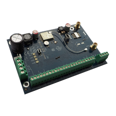
Trikdis SP231 Assembly instructions

©1997-2015 Trikdis 2 www.trikdis.com
Control Panel SP231
General properties
8 zones (possibility to expand to 32);
9 zone functions;
Exclusive zone for two-wire smoke
detector;
8 partitions;
Internal clock;
Control of temperature sensors;
Tamper tracking;
Anti-Masking tracking;
Convenient default settings for fast
installation of the security system.
Alarm control
44 alarm control codes;
Remote control: by phone call or SMS
message;
Control devices: “Trikdis” keyboard
Protegus SK130LED, SK232LED, “Paradox”
keyboard K32+, K32LED, K636, K10LED,
iButton keys, coded or other switches;
“Bypass”, “Door Chime”, “Tamper”,
“Shutdown”, “Anti-Masking”, “Force Arm”
“Bellsquawk” “Re-Arm” etc. functions.
Power supply:
Main supply from 16-18 V AC or 16-24 V DC
source
Back-up supply from 12 V battery
PGM outputs:
5 PGM outputs (3 PGM, 1 Bell, 1 LED);
9 PGM output functions;
PGM output remote control.
Setting of control panel operation
parameters
Software “TrikdisConfig” via USB;
In remote mode –via GPRS using
“TrikdisConfig” or “IPcom Control”
software.
Transmission of reports:
Two slots for SIM cards;
Transmission of encrypted reports to the
main or back-up CMS IP address via GPRS.
If GPRS connection is lost, the reports shall
be sent by SMS messages;
Continuous control of communication
channel;
Sending of reports when the temperature
comes outside the allowable set range;
Event reports shall be transmitted by
Contact ID codes;
Sending of SMS messages with the user
defined event text to 5 mobile phones;
Sending of temperature values by SMS
messages;
Warning calls to 2 phones about the
occurred event;
Event memory shall store at least 2000 last
events.
Control panel SP231 –intrusion (to premises) and fire alarming system (alarm system’s) processor part with
integrated GSM/GPRS communicator. The control panel allows the user to switch on the alarm conveniently to
protect the premises in the preferred mode and thus control the signals of different sensors and react to them.
Upon occurrence of any system event, its report via GSM connection shall be transmitted to the Centralised
Monitoring Station (CMS) and/or mobile phones of users.

©1997-2015 Trikdis 3 www.trikdis.com
Control Panel SP231
Warranty and liability limitations
The control panel is provided with a 24 months warranty to become effective from the purchase-sales date.
The warranty period shall ensure free of charge repair of troubles occurred due to the manufacturer fault.
The warranty shall be applied, if the control panel is installed by qualified specialists according to this
document.
The control panel for repair shall be provided in the manufacturer package together with a defect report
with the indicated nature of trouble.
Upon expiry of the warranty period the maintenance and repair of the control panel shall be performed at
the buyer's expense.
The warranty may be terminated prematurely in the following cases:
The control panel was repaired or was attempted to repair by an unauthorized person;
The control panel was used not for its intended purpose;
The control panel was stored and/or installed in an inappropriate premises with inappropriate climate
conditions, aggressive chemical environment;
The control panel was mechanically broken and/or intentionally damaged;
The control panel was damaged due to force-majeure (lightning discharge etc.) circumstances.
The manufacturer shall not be liable for the following:
control panel malfunctions, if the control panel was installed or used not according to its operation
manual;
control panel malfunctions, if they occurred upon malfunctioning, lost GSM/GPRS/Internet connection
or upon occurrence of troubles in the network operator networks;
termination or restriction of GSM/GPRS/Internet communication services to the control panel buyer or
to the control panel user, and shall not reimburse the control panel buyer or the control panel user for
the occurred property or non-property losses;
termination or restriction of electrical power supply to the control panel buyer or to the control panel
user, and shall not reimburse the control panel buyer or the control panel user for the occurred property
or non-property losses;
robbery, fire of premises or other incurred losses to the control panel buyer or to the control panel user,
and shall not reimburse the control panel buyer or the control panel user for the occurred property or
non-property losses as a result of these events.

©1997-2015 Trikdis 4 www.trikdis.com
Control Panel SP231
Safety requirements
Prior to using the control panel, you must get familiar with this manual.
Control panel SP231 –electrical facility, thus it shall be installed and serviced only by qualified specialists
following this document.
During installation of the control panel its power supply must be switched off!
In the premises the control panel shall be installed in the restricted access zones and at a safe distance from
sensitive electronic equipment. The control panel is not resistant to vibration, other mechanical impact, moisture
and aggressive chemical environment. Control panel shall comply with the requirements of Standard EN 50131
applied to environmental impact resistance Class II.
The used housings, transformers, batteries and programming devices shall comply with the
safety requirements established in the Standard EN 60950.
The device shall be connected to 230 V voltage 50 Hz frequency mains power through the Class
II transformer reducing voltage down to 16 –18 V or to 16 –24 V direct current source. To
ensure back-up supply a battery of 12 V and at least 7 Ah capacity shall be used. The current
consumption depends on the power of the connected external devices.
Protection of the power supply circuit shall be ensured with the installed two-pole automatic
safety switch. The dividing gap between the switch off contacts shall be at least 3 mm. The safety
switch shall be installed in the place known to the specialists servicing the control panel.
Cut-off of the control panel from the electricity network:
- from alternating current network –upon switching off the automatic safety switch;
- from the battery –by disconnecting the terminals.

©1997-2015 Trikdis 5 www.trikdis.com
Control Panel SP231
Content
1TECHNICAL PARAMETERS .................................... 6
2ALARM SYSTEM POWER SUPPLY ......................... 7
2.1 MAIN SUPPLY .....................................................7
2.2 BACK-UP SUPPLY .................................................7
2.3 BATTERY SUPPLY..................................................7
3CONTROL PANEL ASSEMBLIES ............................. 8
3.1 CONTROL PANEL SP231 .......................................8
3.2 CONTROL PANEL SP231 KIT .................................8
3.3 CONTROL PANEL SP231 KITI.................................8
4CONTROL PANEL STRUCTURE .............................. 9
4.1 PURPOSE OF TERMINALS .....................................10
4.2 LIGHT INDICATION..............................................10
5SYSTEM INSTALLATION.......................................11
5.1 RECOMMENDED INSTALLATION PROCEDURE............11
5.1.1 Control panel fastening in the mounting
housing 11
5.1.2 Equipment connection sequence............. 12
5.1.3 Recommendations for setting the control
panel operation parameters................................. 12
5.1.4 Alarm system operation testing .............. 14
5.2 COMPATIBLE MODULES.......................................15
5.3 CONNECTION OF SENSORS ...................................15
5.4 CONNECTION OF SMOKE DETECTORS......................16
5.5 CONNECTION OF EQUIPMENT TERMINALS TO PGM
OUTPUTS 16
5.6 CONNECTION OF REPORT TRANSMISSION DEVICES ....17
5.7 CONNECTION OF TEMPERATURE SENSORS,IBUTTON KEY
READERS 17
5.8 CONNECTION OF KEYBOARDS,INPUT EXPANDERS .....18
5.9 CONNECTION OF WIRELESS SENSORS......................18
6CONFIGURATION OF CONTROL PANEL OPERATION
19
6.1 CONNECT TO CONTROL PANEL ..............................19
6.1.1 Connect with USB cable........................... 19
6.1.2 Connect in remote mode ......................... 19
6.1.3 Changing of settings by SMS messages... 20
6.2 DESCRIPTION OF TRIKDISCONFIG PROGRAM............21
6.3 USER ACCESS ....................................................22
6.3.1 Control panel configuration .................... 22
6.3.2 Control panel control............................... 23
6.4 SYSTEM USER INITIAL LOGIN CODES .......................23
6.5 SYSTEM PARAMETERS.........................................24
6.5.1 General system parameters .................... 24
6.5.2 Resetting of initial parameters................ 24
6.5.3 Setting of control panel clock .................. 25
6.5.4 Regular connectivity checks .................... 25
6.5.5 Keyboard parameters.............................. 25
6.6 SYSTEM TROUBLES .............................................26
6.6.1 Tamper recognition ................................. 27
6.6.2 Control panel watch-dog......................... 28
6.7 ZONE PARAMETERS ............................................28
6.7.1 Main zone parameters ............................ 28
6.7.2 Parameters of zone event reports ........... 29
6.7.3 Zone function description ........................ 30
6.8 PARTITION PARAMETERS .....................................30
6.9 USER ACCESS PARAMETERS..................................32
6.9.1 iButton key code registering.................... 32
6.10 SIM CARD PARAMETERS .....................................33
6.11 REPORT TRANSMISSION TO CMS..........................33
6.12 REPORT TRANSMISSION TO USER...........................35
6.12.1 Message texts to User......................... 37
6.13 PGM OUTPUT CONFIGURATION ...........................38
6.13.1 PGM output operation descriptions.... 39
6.13.2 PGM output remote control................ 41
6.14 CONTROL BY CALL ..............................................41
6.14.1 Partition control .................................. 41
6.14.2 PGM Output control............................ 41
6.15 TRANSMISSION MODULE REGISTRATION .................42
6.16 KEYPADS AND EXPANDERS REGISTRATION ...............43
6.17 WIRELESS SENSORS REGISTRATION ........................44
6.17.1 Detectors............................................. 44
6.17.2 Sirens................................................... 46
6.17.3 Pendants ............................................. 47
6.17.4 Keypad ................................................ 48
6.18 SETTING OF TEMPERATURE METERING REPORT
CHARACTERISTICS............................................................49
6.19 SETTING OF EVENT REPORTS.................................50
6.20 EVENT LOG.......................................................50
6.21 CONTROL PANEL FIRMWARE UPGRADING................51
7PROGRAMMING AND CONTROL BY SMS
MESSAGES ..................................................................52

Control panel SP231 Technical parameters
©1997-2015 Trikdis 6 www.trikdis.com
1Technical parameters
Name
Description
Value
Units
Supply voltage
From alternating current source
16-18
V
From direct current source
16-24
V
Current
consumption
In standby mode
80
mA
When sending data
Up to 150
mA
Between [AUX+]
and [C]
terminals
Output DC voltage (level of impulses shall not exceed 200 mV).
13.6
(10-14)
V
1
A
Maximum allowable current consumption
Note: If the supply limits via “AUX” outputs are exceeded, the supply
to the connected devices shall be switched off automatically
2
A
Between [+5V]
and [C]
terminals
Output DC voltage (level of impulses shall not exceed 100 mV).
Note: If the supply limits via “+5V” output are exceeded, the supply
to the connected devices shall be switched off automatically
5
(4.9-5.1)
V
0.2
A
Surge protection
All the control panel terminal block terminals shall be protected
against static voltage jumps
2000
V
PGM1-PGM3
Programmable OC (open collector) type output terminals for
switching on/off of various devices automatically or by remote
control command (create “minus”)
30
V
0.5
A
BELL- (PGM4)
Programmable OC (open collector) type output terminal for
automatic switching on of the outdoor or indoor sirens (create
“minus”)
30
V
1
A
LED (PGM5)
Programmable OC (open collector) type output terminal with 5.1 kΩ
resistor for connecting the LED cathode (-) (create “minus”).
30
V
0.1
A
Operating
environment
At relative humidity below 80% at +20C, without condensation
From -25
up to +50
C
Control panel
dimensions
-
117x74x2
5
mm
Weight
-
0.1
kg
Report transmission technology
Name
Description
Report transmission to CMS
Complies with criteria of operating properties ATS5 established in
Standards EN 50131 and EN 50136 and applied to Grade III class
equipment
GSM/GPRS modem
Integrated quad-band SIM800H
850 / 900 / 1800 / 1900 MHz
Communication with CMS
technologies
TCP/IP or UDP/IP via GPRS, SMS messages
Report transmission protocols
TRK_TCP or TRK_UDP
Report encoding
Protocol Contact ID codes
Report encryption
Yes, using 6 symbol encryption key

Control panel SP231 Alarm system power supply
©1997-2015 Trikdis 7 www.trikdis.com
2Alarm system power supply
2.1 Main supply
The control panel and all alarm system can be fed from the alternating or direct current source. In both cases,
to ensure an uninterrupted supply to the system, the control panel shall be additionally connected to a back-up
supply source –12 V battery. To ensure the requirements of Standard EN50131, in case of cut-off from the
main supply source, the back-up supply battery shall be of sufficient capacity to provide power from the back-
up source to the system for 12 hours to comply with Grade II requirements or for 60 hours to comply with
Grade III requirements. Assess the current consumption of auxiliary devices, which is provided in chapter 5.2
„Compatible modules“.
2.2 Back-up supply
Upon interruption of power supply to the system from the main supply source, the event AC Failure report shall
be formed and the control panel shall automatically switch over the system for its feeding from the back-up
supply –12 V battery. When the battery voltage decreases down to 11.5 V, the event Low Battery report shall
be formed. When the battery discharges below 9.5 V, the event Battery Missing/Dead report shall be formed
and the battery shall be disconnected. Upon restoration of the AC mains voltage, the AC Restore report shall be
formed and the battery charging process shall start automatically. The desired charging current from 0.1 to 2.0
A can be set during programming the control panel, see 6.5.1 „General system parameters“. When the battery
voltage restores to 12.6 V, the event Battery Restore report shall be formed.
2.3 Battery supply
In individual case, e.g., for testing, the control panel and all the alarm system can be supplied not through the
main supply port, but only through a back-up supply port, e.g., only from 12 V battery. In this case, in order to
start the control panel (system) it is necessary to connect the battery to the control panel –BAT+ port and click
the circuit board button BAT_ON (see 4 “Control panel structure”).

Control panel SP231 Control panel assemblies
©1997-2015 Trikdis 8 www.trikdis.com
3Control panel assemblies
3.1 Control panel SP231
Control panel SP231 circuit board
1 pc.
Battery connection wire
1 pc.
Resistors 2.2 kΩ
16 pcs.
Plastic holder (fasteners)
4 pcs.
3.2 Control panel SP231 KIT
Control panel SP231 circuit board embedded in the metal housing
1 pc.
Metal housing K01 with 40 VA transformer
1 pcs.
Resistors 2.2 kΩ
16 pcs.
Stick-on GSM antenna ANT04 with 2.5 m length cable
1 pc.
Battery connection wire
1 pc.
Tamper sensor
1 pc.
Terminal block with 0,5 A fuse
1 pc.
3.3 Control panel SP231 KITi
Control panel SP231 circuit board embedded in the metal housing
1 pc.
Metal housing K02 with Mean Well impulse supply source
1 pc.
Resistors 2.2 kΩ
16 pcs.
Stick-on GSM antenna ANT04 with 2.5 m length cable
1 pc.
Battery connection wire
1 pc.
Tamper sensor
1 pc.
Terminal block with 3,15 A fuse
1 pc.
Note: USB wire (Mini-B type), which is designed for control panel programming, is not included.

Control panel SP231 Control panel structure
©1997-2015 Trikdis 9 www.trikdis.com
4Control panel structure
1.
RESET button
7.
GSM antenna port
2.
Communication and operation light indication
8.
SIM1 card holder
3.
Back-up supply port
9.
SIM2 card holder
4.
Main supply terminal block
10.
USB port for configuration of the control panel
operation parameters
5.
BAT_ON button is designed for starting the
control panel, when the DC voltage source is
connected to the back-up supply terminal block
11.
1-wire bus terminal block
6.
Terminal block for peripherals

Control panel SP231 Control panel structure
©1997-2015 Trikdis 10 www.trikdis.com
4.1 Purpose of terminals
Main supply terminal block
Terminal
Description
16V AC
16-24V DC
Main supply contacts shall be connected either to 16 –18 V AC or 16 –24 V DC
source.
Back-up supply port
Terminal
Description
-BAT+
Port for connecting the 12 V back-up battery.
Terminal block for peripherals
Terminal
Description
PGM1-PGM3
Programmable operation output terminals for connecting the indicators and
remotely controlled equipment.
BELL+, BELL-
Contacts for connecting the siren.
AUX+
Positive 13.6 V DC supply terminal for keyboard(s), indicators and sensors.
C
Negative supply terminal for keyboard(s), indicators and sensors.
YEL
Peripherals (e.g., keyboard) YEL circuit contact (yellow wire).
GRN
Peripherals (e.g., keyboard) GRN circuit contact (green wire).
MCI
Data bus contact for iButton key code reader and/or other report transmission
devices (e.g., radio transmitter).
ZN1-ZN8
Contacts for connecting the sensor control circuits. The contact ZN8 can be used for
connecting the 2-wire smoke detectors.
1-wire bus terminal block
Terminal
Description
LED
The contact for connecting the premises protection mode indicator, e.g., iButton
key reader LED cathode (-) (PGM5).
+5V
Positive 1-wire devices 5V DC supply contact.
1W
1-wire devices data circuit contact (iButton keys, temperature sensors)
C
Negative 1-wire devices supply contact.
4.2 Light indication
LED indicator
Operation
Value
“NET2”
shows log on
to GSM network
statuses using card
SIM2
Off
Not available or impossible to read SIM2 card.
Flashing green
SIM2 card registration in GSM network in progress.
Solid green
SIM2 card is registered in GSM network.
Frequently flashing green
SIM2 card PIN code error.
Flashing red
Number of flashes (below 10) show GSM field strength.
“NET1”
shows log on
to GSM network
statuses using card
SIM1
Off
Not available or impossible to read SIM1 card.
Flashing green
SIM1 card registration in GSM network in progress.
Solid green
SIM1 card is registered in GSM network.
Frequently flashing green
SIM1 card PIN code error.
Flashing red
Number of flashes (below 10) show GSM field strength.
“Data”
shows broadcasting
Solid green
The control panel memory contains unsent reports.
Flashing green
Transmission of reports to indicated addresses.
“PWR”
shows power
supply status,
programming
mode.
All are off
Power is off or battery voltage is lower than 9.5 V.
Flashing green
Supply voltage is sufficient.
Flashing red
Low supply voltage (< 11.5 V).
Flashes green and red in
turns
Start-up of the control panel operation software
(duration approx. 7 sec.).

Control panel SP231 System installation
©1997-2015 Trikdis 11 www.trikdis.com
5System installation
5.1 Recommended installation procedure
System planning:
Draw the plan of premises and indicate the zones for installation of the mounting housing with a
control panel, keyboard(s), indicators, equipment to be remotely controlled through the control panel
or controlled automatically by the control panel.
Upon assessment of the premises, requirements set to their protection and properties of possible
sensors, select the types of sensors, their number and places, where they should be fastened.
5.1.1 Control panel fastening in the mounting housing
The control panel circuit board shall be installed into
the mounting housing equipped with the reducing
transformer with 500 mA fuse and provided place
for a back-up supply battery.
Reinforce the control panel into the selected plastic
or metal mounting housing using plastic distance
holders of the control panel circuit board. Upon
choosing the metal housing, ensure its grounding
during installation. The used housing must comply
with the requirements of Standard EN 60950 and EN
50131.
5.1.1.1 SP231 circuit board dimensions
The figure shows the dimensions (in mm) of the control panel and its fastening holes and their locations.
Plastic distance holders

Control panel SP231 System installation
©1997-2015 Trikdis 12 www.trikdis.com
5.1.2 Equipment connection sequence
1) Connect the GSM antenna to the antenna port.
2) Insert the SIM card(s), which are already registered in the GSM network, into the SIM card holders. Card
holder SIM1 is the main card holder. The card inserted into SIM1 shall have a priority in operation, and
SIM2 shall be operated only upon malfunction of SIM1.
3) Following the provided diagrams and connection diagrams of every product intended for connection,
connect the magnetic contacts of windows and doors, motion, fire and other sensors, indicators,
keyboards, controlled devices. Connect the housing door tamper sensors and wall mounted tamper
sensors to the control panel terminals.
4) Connect the main supply source wires to the control panel AC/DC terminals. Switch the main supply on.
SP231 shall automatically recognise the correctly connected keyboards, expanders, interfaces, sensors
to the 1-wire and YEL/GRN buses and shall register them in the system.
5) Install a back-up supply battery into the mounting housing. Connect its wires to the control panel back-
up supply source terminals BAT+ / BAT–. Verify the battery charging current to ensure it is charged in
due time.
5.1.3 Recommendations for setting the control panel operation parameters
1) The first log on to the control panel shall be via USB cable (see 6.1.1 “Connect with USB cable”).
2) System settings:
a. Partitions
If the premises have several areas, the protection of which is preferred to be switched on
separately, the alarm system can be divided into partitions. Regarding dividing the system and
setting the necessary partition attributes see 6.8 “Partition parameters".
b. Zones
Parameters regarding setting of every zone according to sensor properties and preferred alarm
operation after an event takes place in this zone. If the alarm system is divided into partitions,
every zone can be assigned to the preferred partition. See 6.7 “Zone parameters”.
Note
The battery shall be fully charged no longer than within 72 hours so the alarm system complies with Grade
II class or within 24 hours to comply with Grade III class.

Control panel SP231 System installation
©1997-2015 Trikdis 13 www.trikdis.com
c. Users
In order to control the alarm system by means of a keyboard, iButton key or phone call (SMS
message), the “User” level users shall be created. Regarding creating “User” and assigning the
rights to them see 6.9 “User access parameters”.
3) Sending of reports:
a. Time setting
In order to receive the reports with a precise event timestamp, it is necessary to set clock time
in the control panel, see 6.5.3 “Setting of control panel clock”.
b. Enabling report sending
In the control panel with manufacturer set primary configuration the sending function of all
event reports is enabled. Regarding enabling or again disabling sending of the desired event
report, see 6.19 “Setting of event reports”.
c. SIM card parameters
If report sending is provided via GSM/GPRS, it is necessary to set the parameters of used SIM
card(s), see 6.10 “SIM card parameters”.
d. Reports to the Central Monitoring Station
Report s to the Central Monitoring Station shall be transmitted only via specified communication
channels. Regarding setting of parameters for report transmission to the Central Monitoring
Station see 6.11 “Report transmission to CMS ”.
e. Reports to user
Event reports to the user can be sent by SMS messages, and by calling the system shall warn on
occurrence of an event. Regarding correct setting of parameters for report transmission to the
user mobile phone see 6.12 “Report transmission to user”.
4) System remote control:
a. User access
In remote mode (by phone call and/or SMS message) the alarm system can be controlled only
by those users, whose phone numbers are entered into the user list. Regarding correct entering
of the phone numbers see 6.9 “User access parameters”.
b. Control by phone call
By a phone call it is possible not only to switch on/off the protection of all or part of premises,
but also control (start or stop) the equipment connected to PGM terminals. Regarding setting
procedure so it was possible by a phone call to change the status of the preferred PGM terminal,
which is connected to the equipment control circuit, see 6.14 “Control by call”.
c. Control by SMS messages
Using SMS messages it is possible to change some control panel operation parameters, switch
on/off the protection of all or part of premises, also control (start or stop) the equipment
connected to PGM terminals. The list of programming commands sent by SMS messages is as
follows: 7 “Programming and control by SMS messages”, and regarding setting procedure so it
was possible by SMS message to change the status of the preferred PGM terminal, which is
connected to the equipment control circuit, see 6.13.2 “PGM output remote control”.
5) Extra:
a. Changing of control codes
It is recommended to change the manufacturer set default values of alarm control and control
panel configuration codes that are known only to You.
Master user code shall be changed in the software menu branch Users.
Remote SMS control code shall be changed in the software menu branch Reporting
column User reporting field SMS reporting.
Log on to TrikdisConfig shall be changed in the software menu branch System options
column System administration.

Control panel SP231 System installation
©1997-2015 Trikdis 14 www.trikdis.com
b. Registration of MCI modules
If compatible equipment is connected to the control panel MCI data bus to be recognised by the
control panel and made a communication with it, this equipment shall be registered manually.
Regarding registering, see 6.15 “Transmission module registration”.
5.1.4 Alarm system operation testing
Upon completion of the alarm system installation, it shall be tested for correct operation.
5.1.4.1 Walk-test function
Operation of sensors and siren can be tested by carrying out a Walk-test function by using Trikdis Protegus
SK130 or SK232 keyboards. The following shall be done:
1. Press the button [OK].
2. Enter installer (Installer) code.
3. Press the button [TRB].
a. The buttons STAY and ARM shall start flashing and the alarm shall switch over to the testing
mode.
b. Due to change of the zone statuses, the sirens and keyboard buzzer shall beep by informing
about the zone operation.
c. If during testing the sensor fuse has been tampered or the protection mode is on, the testing
mode shall terminate automatically.
To switch off the mode, repeat the procedure as switching it on.
5.1.4.2 Testing of report transmission system
If GRPS network parameters are correctly set with the Central Monitoring Station addresses, upon switching on
the power supply to the system the following shall take place:
a) A report E305 System Reset shall be sent.
b) If compatible, but unregistered, modules are connected to the control panel YEL/GRN data bus, there
shall be sent as many reports R333 Expansion Module Restore as there are to be newly registered
modules.
c) If in the control panel, communication control parameters the communication verification signal PING is
on, a report E760 (Control panel PING signal) shall be sent. When the IP receiver gets the report, it shall
start automatic control of the communication channel with the control panel.
Also, it is possible to manually formulate the communication testing report E602 (Periodical Test). It is
recommended to inform in advance the security service about the testing.
Testing of the report transmission by using Trikdis Protegus SK130 or SK232 keyboards shall be as follows:
1. Press the button [OK].
2. Enter installer (Installer) code.
3. Press the button [MEM].

Control panel SP231 System installation
©1997-2015 Trikdis 15 www.trikdis.com
5.2 Compatible modules
Product code
Bus
Purpose
Current
consumption
Trikdis PROTEGUS
SK232LED W/B
Y/G
2 partitions, 32 zone LED keyboard with touch-
sensitive keys, white or black glass surface
up to 150 mA
Trikdis PROTEGUS
SK130LED W/B
Y/G
16 zone LED keyboard with touch-sensitive keys,
white or black glass surface
up to 150 mA
Paradox K32+
Y/G
32 zone LED keyboard
up to 150 mA
Paradox K32LED
Y/G
32 zone LED keyboard
up to 150 mA
Paradox K10LEDV
Y/G
10 zone LED vertical keyboard
up to 100 mA
Paradox K10LEDH
Y/G
10 zone LED horizontal keyboard
up to 100 mA
Paradox K636
Y/G
10 zone LED keyboard
up to 100 mA
CZ8
Y/G
8 zone input expansion module
50 mA
W131
MCI
Interface with iButton key code reader
30 mA
T10R
MCI
Radio transmitter able to send control panel event
reports at VHF range radio frequencies
standby - 50 mA
sending - up to 1 A
E10C
MCI
Ethernet communicator able to send control panel
event reports via internet networks
standby - 60 mA
sending –up to
100 mA
G10D
MCI
GSM&GPRS communicator able to send control
panel event reports via GPRS and/or SMS.
standby - 60 mA
sending –up to
250 mA
CZ-DALLAS
1-wire
iButton key reader
up to 25 mA
DS18B20
DS18S20
1-wire
Temperature sensor Dallas. Measuring range from -
55°C to +125°C
1 µA
5.3 Connection of sensors
The control panel circuit board has eight terminals ZN1–ZN8 (inputs) for connection of sensor control circuits.
When using input expanders CZ8, the number of outputs can be increased up to 32. Regarding setting of every
input as a zone, i.e. assigning the zone attributes: circuit type (EOL, NC...), sensitivity to short-term circuit
events, zone function (“Delay”, “Instant”...) see 6.7 “Zone parameters”.
Normally closed
circuit (NC).
Normally open
circuit (NO).
Normally open circuit
with end of line resistor
(EOL, End of Line).
Normally closed circuit with end
of line resistor (EOL, End of
Line).
Normally closed circuit with end of line
resistor and tamper recognition (NC with
EOL & tamper recognition).
Normally closed circuit with tamper anti-masking
recognition (NC with tamper & anti-masking recognition).

Control panel SP231 System installation
©1997-2015 Trikdis 16 www.trikdis.com
5.4 Connection of smoke detectors
In order to connect the control circuit of the smoke detector to the selected input, it is necessary that this input
was “Fire” zone, i.e. this input must be with the set “Fire” zone function (see 6.7.1 “Main zone ”).
When connecting the four-wire smoke detector circuit to the selected PGM output, this output shall be with the
set Fire reset function (see 6.13 “
PGM output configuration”).
ZN8 input can be dedicated namely for connecting the two-wire smoke detectors (see 6.7.1.2 “Setting of Fire
zones”).
Four-wire smoke detectors
Two-wire smoke detectors
5.5 Connection of equipment terminals to PGM outputs
PGM1-PGM3 - three terminals of open
collector,
BELL-(PGM4) - open collector terminal for
connecting the siren,
LED (PGM5) - collector terminal with 5K1
resistor.
Regarding all possible operation modes of
PGM outputs see 6.13.1 “
PGM output operation descriptions”.
Regarding changing of initial output values
see 6.13 “
PGM output configuration”.
Connection of sirens
PGM initial settings
1. Remote Control
2. Remote Control
3. Remote Control
4. Bell
5. System State
Connection of alarm (controlled) devices

Control panel SP231 System installation
©1997-2015 Trikdis 17 www.trikdis.com
Connection of remotely controlled terminals
5.6 Connection of report transmission devices
Report transmission devices
(T10R, E10C, G10D etc.) shall be
connected to a 1-wire data bus
MCI. The maximum length of the
bus shall be up to 100 m, with a
possibility to connect up to 4
devices. The control panel shall
not automatically register the
connected devices. Registration
shall be done manually (see 6.15
“
Transmission module
registration”).
5.7 Connection of temperature sensors, iButton key readers
It is possible to connect iButton key
readers and/or DS18B20 or DS18S20
temperature sensors to a 1-wire data
bus. The total length of the bus shall not
exceed 30 m, with a possibility to
connect up to 10 devices.
Circuit board terminal +5V is designed
for supply of 5 V DC to devices
connected to 1-wire bus. Allowable
output current shall not exceed 0.2 A.
The output shall be protected against
overload. Upon exceeding the allowable
current, the supply shall be cut-off
automatically. The control panel shall
automatically recognise and register the
connected devices.
When connecting more than one sensor with longer than 0.5 m wires,
for connections it is recommended to use twisted pair cable (UTP, STP).

Control panel SP231 System installation
©1997-2015 Trikdis 18 www.trikdis.com
Connection of iButton key readers
A –iButton key readers can be connected directly to 1-wire data bus. In addition, schematic shows the colour code
of wires for LED connection.
B –iButton key readers, when connecting at distances exceeding 30 m to the control panel, can be connected
using W131 expansion module.
5.8 Connection of keyboards, input expanders
The 2-wire data bus Y/G (a.k.a.
YEL/GRN) can be connected to
“Trikdis” Protegus SK232 LED B/W,
Protegus SK130LED B/W, “Paradox”
K32+, K32LED, K636, K10LED
keyboards and/or input ZN number
expanders CZ8. The total length of
the bus shall not exceed 300 m, with
a possibility to connect in parallel up
to 16 devices. The control panel shall
automatically recognise and register
the connected devices. Regarding
device unregistering see “
Keypads and expanders registration”.
5.9 Connection of wireless sensors
In order to connect the wireless
sensors, it is necessary to connect RF-
MOD module to control panel`s serial
port (the newest SP231 already have
soldered 4 pins plug to connect RF-
MOD. For older version –solder 4
pins plug in the marked “SERIAL”
holes).
To register wireless sensors in the
system refer to 6.17 Wireless sensor
registration

Control panel SP231 Configuration of control panel operation
©1997-2015 Trikdis 19 www.trikdis.com
6Configuration of control panel operation
The control panel operation parameters shall be set by software TrikdisConfig, which operates in OS MS
Windows environment. It is possible to connect to the control panel by using a USB cable or remotely, by
communicating with the control panel via GPRS communication. The software is available on the website
www.trikdis.com. Some control panel parameters can also be changed remotely by SMS messages.
6.1 Connect to control panel
6.1.1 Connect with USB cable
1) The computer shall have installed the following: parameter setting software TrikdisConfig and
software Microsoft.NET Framework 4.
2) After the software is in place, connect the control panel and the computer with the USB cable. Power
supply via USB port is sufficient to set the control panel operation parameters, so additional supply
is not necessary. Start the parameter setting software TrikdisConfig. The software shall automatically
recognise the connected device and open the window for its programming.
3) In order to read the parameters entered in the control panel, click the button Read and in the pop-
up table enter your (Admin or Installer) code (if the administrator initial code exists, the code shall
not be prompted).
4) After the first time reading of the control panel operation parameters, the software shall show the
manufacturer set default control panel operation parameters. After changing the parameters, click
the software button Write to enter the changes in the control panel memory. When configuration is
complete, shut down the software TrikdisConfig and unplug the USB cable from the control panel
USB port.
6.1.2 Connect in remote mode
Configuration of the control panel settings in remote mode shall be carried out via GPRS communication. For
both softwares TrikdisConfig and IPcom the appropriate GPRS communication settings shall be set. The manual
of the control panel shows how to do it and how to connect by using TrikdisConfig software. The description
how to connect with IPcom software is provided in the supporting documentation to this software.
6.1.2.1 GPRS communication settings
1) Ensure that SIM card has a disabled PIN code protection.
2) Insert SIM card with enabled GPRS communication service into the control panel SIM 1 slot. For
information how to enable this service please contact Your GSM service provider.
3) Add phone number the user, because only from listed numbers it is available to use all SMS commands.
SMS commands must be sent to the inserted SIM card’s number.
Command to add new phone number:
CFG [SMS password] ˽ 01 ˽ [USER Code] # [User Phone No.] #
CFG –beginning of SMS command, [SMS password] –six digit SMS password, 01 –command code,
[User code] –user code, [User phone No.] –user phone number, # - symbol to end value, “˽ “– marks the
space symbol in SMS message.
An example adding a phone number to Master user, while using default password values:
“CFG123456 01 1234#+37061111111#”
Note. When the Grade 2/3 protection class setting function is enabled, the remote control and
configuration function of the control panel shall be disabled automatically.

Control panel SP231 Configuration of control panel operation
©1997-2015 Trikdis 20 www.trikdis.com
4) Setup an inserted SIM1 card GSM network parameters. Command to set operator parameters:
PSW XXXXXX ˽ 12 ˽ APN# LOGIN# PSW###
PSW XXXXXX –beginning of SMS command and its password, 12 –changing network parameters
command, APN –gateway name (up to 50 symbols), LOGIN –user name (up to 29 symbols), PSW –
user password (up to 29 symbols), # - symbol to end value.
Example: “PSW123456 12 gprs.net#web#web###”
If network does not have user name nor password, fields must be left empty.
Example: “PSW123456 12 gprs.net#####”
5) Connection to the remote server must be enabled in a control panel. Command to enable connection:
PSW XXXXXX ˽ 94 ˽ 1
PSW XXXXXX –beginning of SMS command and its password, 94 –connection to the remote server
command, 1 –connection enabling value (0 –to disable).
Example: “PSW123456 94 1”
6) It is required to know IMEI address of Control Panel. IMEI address can be found on product package or
it can be requested by SMS command:
PSWXXXXX ˽ 97 ˽ 5
PSW XXXXXX –beginning of SMS command and its password, 97 ˽ 5 – request about GSM field
strength, modem IMEI number and control panel software version.
Example: „PSW123465 97 5“
6.1.2.2 Remote log on through TrikdisConfig
1) Make sure that the control panel is connected to supply source and in operation.
2) Start TrikdisConfig software.
3) At the field Remote access, in the field Unique ID enter the control panel GSM/GPRS modem IMEI address.
IMEI address is provided on the product package.
4) In the adjacent field System Name enter the desired name to the module.
5) Press Configure. After successful connection the settings shall be saved.
6.1.3 Changing of settings by SMS messages
Communication by SMS messages is designed for monitoring and control of the alarm system. The list of
commands sent by SMS messages see 7 “Programming and control by SMS messages”.
To activate this function, perform the following actions:
1) Insert the SIM cards, which are already registered with the GSM network provider, into the SIM card
holders.
2) Complete adding phone number to user command as instructed in 6.1.2.1 GPRS communication
settings the third point in a list. Because only from listed numbers it is available to use all SMS
commands.
Other manuals for SP231
1
Table of contents
Other Trikdis Control Panel manuals
Popular Control Panel manuals by other brands
Integrated Technical Vision
Integrated Technical Vision U-PROX HUB LAN user manual
Honeywell
Honeywell PL-1000 Installation and user manual

Edwards
Edwards 2010-2-PAK-900 Registration Guide
Nakanishi
Nakanishi E4000-PB Operation manual
Zamel
Zamel VO-803B manual
Bentel Security
Bentel Security K-NET installation manual

Cooper Menvier
Cooper Menvier Scantronic 9751 Installation and programming guide
Festo
Festo CP-E16-M8 manual

Pyronix
Pyronix OCTAGON II installation instructions
Kasco
Kasco C-25 Installation & operation manual
Groupe Atlantic
Groupe Atlantic NAVISTEM B1000 Instructions for installation, use and maintenance
NAPCO
NAPCO MA3000 Basic operating instructions

