Platinum Tools VDV MapMaster 3.0 T130 User manual

32
IS T130 GJ Rev A 0417
© 2017 Planum Tools, Inc, California USA
T130 User Manual

2
31

30
Contacting Platinum Tools, Inc.
For information on this product or any Platinum Tools product,
please visit us at www.platinumtools.com.
For support or other inquiries, please contact us at:
Phone: 805-384-2777 or 800-749-5873
3
Table of Contents
Overview.......................................................................................... 4
VDV MapMaster Features............................................................... 5
Safety Information ........................................................................... 6
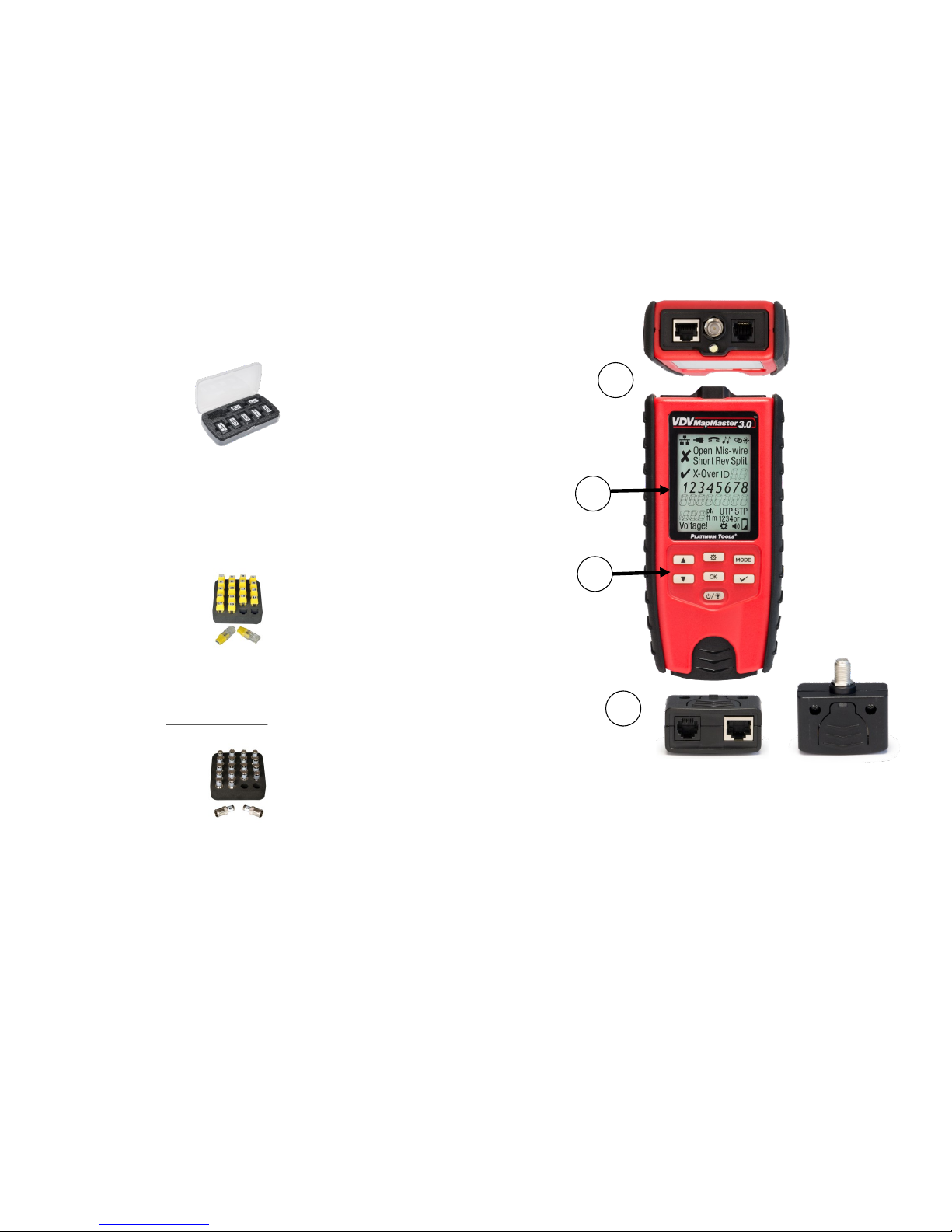
VDV MapMaster 3.0 Parts............................................................... 7
Screen Icons ................................................................................... 9
Test Results and Other Functions................................................. 10
Using the Tester ............................................................................ 12
Cable Testing ................................................................................ 14
Remotes ........................................................................................ 18
Interpreting Test Results ............................................................... 18
Video (Coax) Cables ..................................................................... 20
Voice (POTS) Cables .................................................................... 20
Set Up Menus................................................................................ 21
Setting the Cable Capacitance...................................................... 22
Pass/Fail Settings.......................................................................... 22
Single-Ended Testing .................................................................... 23
Port Link Light ............................................................................... 23
Continuous Loop Testing .............................................................. 24
Backlight and Built-in LED Flashlight ............................................ 24
Tone Mode .................................................................................... 25
Accessories ................................................................................... 26
Specifications ................................................................................ 28
Warranty........................................................................................ 29
Figure 1—Display Screen and Keypad Icons ................................. 8
Figure 2—Wire Map ...................................................................... 12
Figure 3—Mis-Wire ....................................................................... 12
Figure 4—Shorts ........................................................................... 13
Figure 5—Split Pairs ..................................................................... 13
Figure 6—Remote ID Number....................................................... 13
Figure 7—Tester Modes................................................................ 14
Figure 8—Set Up Menu Map......................................................... 16

4
Overview
The VDV MapMaster™ 3.0 is designed to test and measure
lengths of all common low voltage cabling found in today’s
network, video or telephone systems. It also maps the
locations of cable ends by sending a tone on the cable that
can be traced with a tone tracer or by blinking the LED on the
port jack. The VDV MapMaster™ 3.0 has a large, bright back-
lit LCD display and glow-in-the-dark buttons to directly access
each function. The remote stores inside the main unit for ease
of cable testing. The VDV MapMaster™ 3.0 is turned on by
pressing the power button and begins operating in the last
mode used or the selected mode: twisted pair (DATA), coax
(VIDEO), telephone (VOICE), tone generation (TONE) or Port
Link-Blink (LINC).
29
Specifications are subject to change without notice.
Warranty
Platinum Tools warrants this product to be free from defects in
material and workmanship for 12 months for test equipment
and 3 months for cables and accessories from the date of
purchase. Liability is limited to the repair and or replacement of
the product. Warranty excludes batteries included with the
product. NO IMPLIED WARRANTIES OF MERCHANTABILITY
OR FITNESS FOR A PARTICULAR PURPOSE. Platinum
Tools is not liable for consequential damages.
Low Baery Icon ashes when baery voltage
Measurement Technology Capacitance tesng
Length Accuracy Without
Length Constant Accuracy
± 3% plus + 1
Cable Length Measure-
ment
1 to 2,000 CAT5e cable with 15
pF/ length constant
Default Length Constant
(Restored with power on
reset)
Voice (Twisted pair): 17.4 pF/
Video (Coax): 16.5 pF/
Data (Twisted pair): 15 pF/

28
Specifications
Display Large 2.75” Backlit Monochrome LCD
Dimensions 6.8˝ x 3.2˝ x 1.4˝ (17.3 x 8.1 x 3.5 cm)
Weight 10.8 oz. (305 grams) with baery and
remote
Operang
Temperature
0˚C/32˚F to 50˚C/122˚F
Storage
Temperature
-20˚/-4˚F to 60˚C/140˚F
Humidity 10% to 90%, non-condensing
Maximum Voltage
between any two
connector pins
without damage
RJ12/RJ45/F: 50V DC or AC
Baery Life 9V alkaline baery typical
Standby: 4 years
Acve: 425 hours
Cable Types: Shielded or Unshielded; CAT7, CAT6A,
CAT5e, CAT5, CAT4, CAT3, Coax
Maximum Cable
Length Tesng
0 to 1,000 feet (305 meters)
Minimum Cable
Length for Split Pair
Detecon
1.5 feet (0.5 meters)
Maximum Coax
Cable Length
Varies depending on cable resistance.
5
VDV MapMasterTM 3.0 Features
Cable Verification
• Test, Measure, and Map data, coaxial video and voice
cables
• Fault testing for opens, shorts, mis-wires, reverses and
split pairs
• Highly accurate length, opens and split detection using
capacitive technology
• Port Link-Blink to visually identify connected ports on a
switch or router
• Verify end-to-end grounding of shielded data cables
• Single-ended testing for shorts
• Wiremap testing to EIA T568A/B standards and cross-
over cables
• Loop mode for continuous testing
• Recognizes up to 20 unique remote ID numbers for map-
ping cables
• Built-in 4-cadence Tone Generator for audible tracing of
cable runs
• Auto-off and low power consumption for extended battery
life
Conveniences
• Built-in LED Flashlight
• Easy-to-read Large Backlit LCD Display
• Glow-in-the-Dark Buttons
• Audible Beep for Additional Feedback
• Ergonomic Slip-resistant Side Grips
• Self-stored Master Remote - Squeeze remote at finger
grip openings in main unit to remove
• RJ45, RJ12 and F-Jack on Main Unit and Remote

6
Safety Information
To ensure safe operation and service of the tester, follow
these instructions.
Always Check Connectors First!
Poorly terminated RJ45 connectors have the potential to
damage the jacks on the VDV MapMaster™ 3.0. Always
visually inspect an RJ45 connector before inserting it into
the tester. All the contacts should always be recessed into
the plastic housing of the connector.
The use of a Port Saver (Platinum Tools P/N 21025C), a
sacrificial adapter with an RJ45 on one end and an RJ45
jack on the other, is highly recommended to extend the
life of the jack.
Only insert RJ45 connectors into the RJ45 jack in the
tester. Plugging 6-position connectors (RJ12/RJ11) into
the 8-position jack on the tester may damage the outer-
most contacts of the jack unless the connector is specifi-
cally designed for that purpose.
WARNING! Do not attach to AC power.
The VDV MapMaster™ 3.0 is designed for use on
unenergized cabling systems.
Connecting the VDV MapMaster™ 3.0 to live AC power
may damage it and pose a safety hazard for the user.
Failure to observe these warnings
can result in severe injury or death.
27
P/N TP250C ToneSeekerTM Tone Probe
Use with the tone function in your tester to trace cables behind walls
or to identify where the end of a cable is located in a patch panel.
P/N 610025C 5” STP CAT6 Premium Patch Cable
For testing or toning cables terminated in RJ45 jacks and patch pan-
els.
P/N T126C No-Fault Cable
7.5” special RJ12-to-RJ12 No-Fault Cable uses no-fault RJ12 con-
nectors on both ends to assure no damage to the RJ45 jacks. It is the
ideal patch cable to use when mapping or shooting tone.
P/N 21025C RJ45 Port SaverTM (RJ45 male to RJ45 jack adapter)
Extend the life of your tester by using the RJ45 Port Saver as your
sacrificial cable. This eliminates the wear and tear from constantly
plugging in and out of the tester port.
P/N 4007 Hanging Pouch
This compact pouch folds out and hangs. Large enough to accommo-
date the VDV MapMasterTM 3.0 and accessories. Tough black nylon
fabric. Wrap around strap with snap buckle. D-ring for hanging up
rolled-out pouch. Three zippered compartments.

26
Accessories
The following accessories are recommended to
optimize your testing with the MapMaster™ 3.0:
P/N T139C Smart Remote Kit (ID# 2-7)
Maximize efficiency and save time, by eliminating the need to walk
back and forth to test sites. Combine this kit with the master remote
in your Platinum Tools tester to both ‘Test’ and ‘Map/ID’ up to eight
drops/locations simultaneously.
P/N TRK220 Data Remote Set, RJ45, 20 pc
ID/MAP 20 data (twisted pair) cables or data ports/jacks at one
time. Numbered custom RJ45 remotes #1 thru #20 for easy
identification. NOTE: For mapping only!
P/N TRK120 Coax Remote Set, Push-On F Type, 20 pc
Test and ID/MAP 20 video (coax) cables at one time. Numbered
custom F remotes #1 thru #20 for easy identification.
7
VDV MapMasterTM 3.0 Parts
1. Connector ports and built-in LED flashlight (top of tester)
2. Large Backlit LCD Screen
3. Glow-in-the-Dark Keypad
4. Stored Master Remote (Removable) with RJ45, RJ12/11 and
F-female Jacks
1
4
2
3

8
Data Cable
Mode
Coax Cable
Mode
Phone Cable
Mode Tone Mode
PASS
FAIL
Port Link
Mode
Cross-over
Wire Map
Fault(s)
Detected
Remote ID
(Up to 20)
Shield
Detecon
Length or Cable
Capacitance
Value
High Voltage
Warning
Feet or
Meters Sengs
Menu
Beep On
Baery
Strength
Pairs
Detected
Figure 1—Display Screen & Keypad Icons
25
Tone Mode
The Tone Mode generates audio tones on all pairs, a select-
ed pair or a selected pin. These tones can be heard by using
an inductive tone tracer (Platinum Tools TP250C ToneSeek-
erTM). The signal generated on a pair has the signal on one
pin and the complement of the signal on the other pin of the
pair, yielding a nominal 10 Volts peak-to-peak across the
pair.
Figure 9—Tone Setup Menu
Pressing the “OK” key toggles through cable types
(Data, Video, Phone).
Pressing the “Test” key toggles Tone on and off.
Pressing “Up/Down” keys select pins used for Tone.
To change the tone, press the “Setup” key, then press
the “Up/Down” keys to change the cadence. Press the
“OK” key to save the cadence selected. The tone pattern
options are Hi, Lo, HiLo1 and HiLo2. The HiLo options
are dual or warble tones of differing pattern duration.

24
Connect the cable from the switch to the test-
er and press the MODE button until the Link
Light icon and “Linc” is displayed on the
screen, then press “OK”.
If “Linc OFF” is displayed, press the test button (check mark),
to turn it on. To turn the Link Light off, press the test button
until Linc OFF
Continuous Loop Testing
While in a cable test mode, hold Test key for 2+ seconds to
toggle looping on/off.
Backlight and Built-in LED Flashlight
By default, the LCD backlight is turned off when the tester is
powered on.
• To turn the LCD backlight on, with the tester powered on,
press the power button again.
• To turn the backlight off, press and release the power
button.
Note that the backlight and built-in LED are synchronized to
both be turned on or off at the same time.
9
Icon/Term Description
DATA/LAN Cable Test mode
VIDEO/Coax Cable Test Mode
VOICE Cable Test Mode
TONE Mode
Port Link-Blink Mode
Passed Cable Test
Failed Cable Test
Open There is a break in a wire between the ends
Mis-wire The wires in a pair are not in the proper order
Short The pairs are in contact with each other at a point in
the cable
Rev Wires are reversed
Split A wire in one pair is switched with the wire of anoth-
er pair
X-Over Cross-over cable detected
ID no. ID number for an attached remote
VOLTAGE! Voltage higher than 60V has been detected!
UTP/STP End-to-End Shielded Detection
Setup Menu
Audible Beep
Low Battery Indicator
Select Up/Down Keypad Buttons
“OK” Button
Setup Button
Tester Mode Button
Test Button
Power/Backlight & LED Flashlight Button

10
Test Results and Other Functions
PASS, Data Cable,
STP, Remote #1,
35.3 ft
FAIL, Data Cable,
STP, Short on 4/5,
Remote #1, 35.3 ft
FAIL, Data Cable,
STP, Open on 4/5,
Remote #1, 35.3 ft
FAIL, Data Cable,
STP, Split on 4/5
and 7/8 (Splits al-
ways affect at least 2
pairs), 35.3 ft
FAIL, Data Cable,
STP, Mis-wire on
4/5, Remote #1,
35.3 ft
FAIL, Data Cable,
UTP, Open on 1/2,
3/6 and 7/8, Short
on 4/5, remote ID
not detected, 35.3 ft
23
Single-Ended Testing
If no test remote or mapping ID is found, a single-ended test
is performed on the open cable. A single-ended test first
measures the length of all 8 wires. If all wires are greater
than 4 feet, a split-pair test is performed. Also, the wire
lengths are compared to test whether they are all within 10%
of each other. If these conditions are met, the Check icon is
activated and “ONE-End” is displayed.
Splits are identified by flashing the corresponding numeric
icons (Split and X-Over icons activated). If no splits are
found, but some wires are less than 10% of the longest wire,
“diFF LEN” is displayed and the corresponding numeric icons
are flashed.
For single-ended testing:
• A 1-pair cable is declared if the 3-4 pairs are at least 3
feet long and the 2-5 and 1-6 pairs are less than 2 feet.
• A 2-pair cable is declared if the 3-4 and 2-5 pairs are at
least 3 feet long and the 1-6 pair is less than 2 feet.
• A 3-pair cable is declared if all the pairs are at least 3
feet long. If an unconventional configuration of wire pairs
is detected (e.g. 1-6 and 2-5), the expected pair icon
blinks and the Mis-wire icon is activated. Current default
pass criteria are 2-pair, reversed.
• A 4-pair cable is declared if all the pairs are at least 3
feet long. If neither criterion is met, the number of pairs
is left unknown.
Port Link Light
The Port Link Light function allows the tester to “blink” the
port on a switch or router that a data cable is inserted in. In
this mode, the Ethernet LED in the port will blink in the same
frequency as the tester.

22
NOTE: To access the Set PASS Criteria menu, you must
press and hold down the SETTINGS button for more than 2
seconds.
When editing a setting, press the Setup button to return to
Setup loop without saving. Pressing the OK button saves the
setting and returns to the Setup loop menu. Pressing the Test
key saves the current setting and returns to the testing mode.
Pressing the Mode button discards any changes to the cur-
rent setting and returns to the Mode select loop menu.
Setting the Cable Capacitance
The capacitive value is used in measuring the length of a
cable. The values are preset in the tester, but a custom value
can be set for more accurate measurements. To calibrate the
value for a specific cable, use a known length of cable, 15
feet or more is recommended. Test the cable and adjust the
capacitive value until it shows the actual length of the cable.
Press “OK” to save the value. The tester is now set for the
same spool of cable that you used to calibrate the capaci-
tance for.
With AUTO-LENGTH selected, set the capacitance value.
The first pair that does not have a fault will be the pin pair
being displayed. For example, if there is a short on pair 1-2,
pair 3-6 are measured in AUTO-LENGTH and you'll see 3-6
displayed when you set the capacitance value.
Pass/Fail Settings
When the cable does not match the pass criteria (e.g. UTP
instead of an expected STP), the detected condition is dis-
played and the expected one blinks (e.g. UTP icon on, STP
icon blinking). X-Over does not have an alternate icon so it
blinks if there is a mismatch between expected and actual.
11
PASS, Data Cable,
Single-ended test,
shielding not tested,
35.3 ft
FAIL, Data Cable,
Single-ended test,
Split on 4/5 and 7/8,
shielding not tested,
35.3 ft
FAIL, Data Cable,
STP, Cross-over
detected, 35.3 ft
(Tester set in ANY
Cable mode)
TONE mode, Hi Lo
warble, Tone On
Port Link Blink
Mode, Blink On
Data Cable, High
Voltage detected!
Disconnect immedi-
ately to prevent
damage to the tester

12
Using the Tester
The corresponding connectors at the top end of the tester
are labeled the same as their mode switches. An icon for
the currently selected mode will appear or flash on the
screen.
To turn the VDV MapMaster™ 3.0 off when in one of the
cable test modes, press and hold the power button until the
tester powers off.
The top line of numbers (Fig 2) on the display represents
the connector pins on the main unit. The second line of pin
numbers represents the connector pin numbers of the re-
mote, normally being the same as the top line for a one-to-
one wired cable.
Figure 2 - Wire Map
If there is a mis-wire (Fig 3), the pin numbers on the second
line will indicate the pin numbers detected and the “Fail”
icon will appear.
Figure 3 - Mis-Wire
The associated pin numbers of a mis-wired pairs will blink in
the remote row. If no connection was detected for some of
the pins, the first and second line of pin numbers will be
blank in those pin locations. If a short is detected, the sec-
ond line (Fig 4) will have a dash ‘-’ in those positions along
with “Short” appearing.
← Main Unit
← Remote
← Main Unit
← Remote
21
The tester will display the “Pass” icon when all 6 pins are
correctly wired in a one-to-one order. If all 6 pins are
correctly wired in the reverse order, the “Pass” icon
along with a flashing “Rev” icon. Standard telephone
cables used between a phone set and a wall jack are
usually reverse-pinned.
After turning on the Telephone Cable test mode,
subsequent presses of the test button will initialize a new
test cycle. This is useful to immediately begin a new test
when attaching a new cable to the MapMaster™ 3.0.
Set Up Menus (See Figure 8—Set Up Menu Map)
There are two paths for changing the settings:
A. The “General Setup Menu” changes the settings for:
1. Feet or Meters when measuring cable length
2. Setting the capacitance value for a specific cable
3. Turning the audible beep on/off
B. The “Set Pass Criteria Menu” allows you to set the
PASS parameters for a specific configuration including:
1. Shielded or unshielded detection
2. Single or multiple pairs
3. Cross-over (X-Over) for data cables
4. Reverse-wired phones cables
In the “ANY” Cable Configuration setting, the VDV
MapMaster™ 3.0 will test the cable for a standard TIA568
configuration and display UTP if no continuous shield is
detected or STP if a continuous shield is detected. It is likely
that you will use this setting for most if not all your testing, but
the custom settings will allow you to test specific
configurations.

20
Remote-End Wire Map: The bottom line displays the
corresponding pin on the remote-end. Dash lines on
the remote line indicate short pins. No pin numbers
displayed on the remote line are open pairs.
Remote Location ID: In the ID mode, the “ID” icon will be
displayed with the number of the remote ID. If a
remote if in place and a fault in the cable is detected,
an error message of “Open” or “Short” is displayed.
Single-ended Testing: If a remote is not used as in a
“one-end” test, only shorts and splits will be
displayed if detected.
Voltage Detected Warning: If voltage is detected on any
of the tester connectors, the “Voltage!” icon appears.
For accurate testing results, unplug the cable from a
switch or router.
Video (Coax) Cables
Tests for shorts, opens and ID’s up to 20 unique remotes
(P/N TRK120) on the F-connector jack. Connect one end
of the coax cable to the F-connector jack on the top of the
tester. Connect the other end of the coax cable to the
F-connector jack on the master remote and press the test
key to scan for the remote ID. To measure the length of a
cable, DO NOT use a remote.
Voice (POTS) Cables
The Phone test behaves similarly to the Data cable test.
The VDV MapMaster™ 3.0 is designed to test twisted
pair phone cables; using it to test flat cable may result in
false “split” results. The VDV MapMaster™ 3.0 assumes
the 6-position jack on the main unit and the remote will be
used for connecting the tester to the cable run to be
tested.
This mode uses the 3-pair USOC standard to define the
pairs. Connector pins 1-6, 2-5 and 3-4 are the pairs de-
fined by this standard.
13
Note that this tester will not determine which end of a faulty
cable is mis-wired, reversed, or split.
Figure 4 - Shorts
If a split pair (Fig 5) is detected, those pin positions on the
first and second line will be flashing the pin numbers detected
from the remote and the “Split” icon will be flashing. If there
are multiple errors to display, there will be a combination of
the above error will appear.
Figure 5 - Split Pairs
The ID icon (Fig 6) will have a number directly to the right of
it, indicating the remote ID number.
Figure 6 - Remote ID Number
Whenever the “TEL” or “DATA” icons are on, a new test is in
progress . In the coax mode, the “Open”, “Short” or “Pass”
icon will be appear to indicate the results of a test. If the cable
passes, the “ID” icon will be appear as well as a remote ID
number on the bottom line of the display. The “Coax” icon
appears when a test is in progress.
← Main Unit
← Remote
← Main Unit
← Remote

14
The tone generator operates in DATA, COAX and VOICE
modes. In this mode, the conductors or pairs associated with
one of the three connectors are displayed. The specific mode
(DATA, COAX, VOICE or TONE) is selected by pressing the
MODE button. If the VDV MapMaster™ 3.0 was off when the
TONE button is pressed, the last cable test mode used will be
selected and selected pairs are used.
Cable Testing
The top line (Fig 7) displays the cable type test mode,
tone generation and link light modes.
Figure 7 - Tester Modes
Select the test mode by pressing the MODE button until
the correct icon is displayed.
Press OK/Test keys to start the test.
Data Cable Test
Coax Cable Test
Phone Cable Test
19
Interpreting Tests Results
Pass/Special Cables: “Pass” will appear if the cable is a
properly wired 4-pair T568A/B data cable, a 3-pair
one-to-one wired voice cable or a video cable with
no faults. Uplink cables, also known as crossover
or T568A-to-T568B cables, are commonly used to
connect two computers or two hub switches direct-
ly together. Crossover cables are detected and
displayed as “X-Over”.
In addition, “X-Over” is displayed, if a properly
wired cross-over (uplink) cable is recognized. “Rev”
appears if the cable is a properly wired reverse-
pinned voice cable. The wire map will show actual
pin connections if all 8 pins are correctly wired with
the 1-2 and 3-6 pairs crossed.
Cable Faults: The “Fail” icon will only appear if the cable
is not wired to one of the cabling standards. An
open or short error takes precedence over other
faults.
Shielding (Ground) Detection: “STP” appears when a
shielded data cable is properly connected at both
ends. “UTP” appears if there is no end-to-end con-
tinuity in the shielding detected.
Short: It will be flashing if there is a short to a wire in the
cable along with that pin number and the “Short”
indicator.
Tester-End Wire Map: The top line displays the pins on
the tester end in order. These pins are mapped to
the pins on the remote-end shown directly below
them on the LCD.

18
Remotes
There are four types of remotes that can be used with the
tester:
Master Remote –This remote is stored in the lower half
of the tester. It is used for both cable verification
(fault) testing and for mapping. The VDV MapMaster
3.0 master remote has three jacks built into it for
convenient testing: RJ45, RJ12/RJ11 on one side
and an F-female on the other. The Master Remote
has a unique ID #1 as its identifier when used for
mapping.
Smart Remotes –These are test and ID twisted pair re-
motes. With an RJ45 jack on one end and an RJ12/
RJ11 jack on the other end, they are used for fault
testing Data or Telephone cables. They also have
unique ID numbers and are used to map the end
location of the cable. Test remote IDs are shown in
the tester display with a hyphen (e.g. “ID – 4”).
Coax Test and ID Remotes –Coax remotes are used
when testing for shorts and opens in a coax cable.
Each coax remote also has a unique ID number for
mapping cable ends. Do not use a remote when
testing for the open length of cables.
Pressing the O/ID button starts the ID test mode on
the VDV MapMaster™ 3.0. ID/MAP up to 20 loca-
tions at one time with numbered custom ID remotes.
LAN ID-only Remotes –These remotes have a unique ID
number and are only used to map the location of the
jack that the data cable is plugged into.
Note: LAN ID only remotes are not used for cable
testing.
15
Voice/Data Cables - Up/Down keys select pins used for
length, OK/Test keys resume testing (automatically
returns after 5 seconds of no activity). The “LEN Auto”
setting measures the first pin pair it can find without a
short or other detected problem.
The VDV MapMaster™ 3.0 assumes the 8-position jack
on the main unit and the remote will be used for
connecting the tester to the cable run to be tested. The
TIA/EIA 568A/B standard is used to define the pairs.
Connector pins 1-2, 3-6, 4-5 and 7-8 are the pairs defined
by this standard. The A and B standards are the same
except for color-coding and are indistinguishable from
each other by electrical testing.
Specific Pair Length - The VDV MapMaster 3.0 can be
used to measure the length of specific pairs for data and
telephone twisted pair cables. While in DATA or VOICE
cable test mode, pressing the up/down arrow will change
the pair slection to the following options:
Data Cables
AUTO-LENGTH, measures the length of the
first pin pair that doesn’t have a fault (e.g. not
shorted). In most cases, for a data cable that is
good, pair 1-2 will be tested.
1-2, 3-6, 4-5, 7-8
Telephone Cables
AUTO-LENGTH, measures the length of the
first pin pair that doesn’t have a fault (e.g. not
shorted). In most cases, for a phone cable that
is good, pair 3-4 will be tested.
3-4, 2-5, 1-6

16
Figure 8—Set Up Menu Map
17
Set Up Menu Map
This manual suits for next models
2
Table of contents
Other Platinum Tools Cable Tester manuals
Popular Cable Tester manuals by other brands

Kingfisher
Kingfisher KI-TK800 Series Quick reference guide

Steren
Steren HER-605 instruction manual

Sperry instruments
Sperry instruments Cable-Test TT64200 operating instructions

Fluke
Fluke MicroScanner Series Getting started guide

FONESTAR
FONESTAR TCAT-8 quick start guide

Besantek
Besantek BST-LAN12 instruction manual