Page1
Table of Contents
I. Warnings and Cautions ..................................................................................... 4
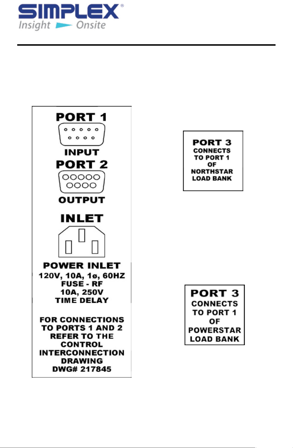
II. Nameplates and Placards.................................................................................. 6
1. Introduction......................................................................................................................... 6
2. Instruction Placards ........................................................................................................... 6
III. Description and Specication..........................................................................11
1. Introduction....................................................................................................................... 11
2. Overview of Use................................................................................................................ 11
3. Capabilities ....................................................................................................................... 11
4. Safety ................................................................................................................................ 12
5. Specications ................................................................................................................... 12
IV. Unpacking ......................................................................................................... 13
1. Introduction....................................................................................................................... 13
2. Included Components and Parts .................................................................................... 13
3. Primary Inspection ........................................................................................................... 13
V. Installation......................................................................................................... 14
1. Introduction....................................................................................................................... 14
2. Load Bank Location ......................................................................................................... 14
VI. Operating Instructions..................................................................................... 16
1. Introduction....................................................................................................................... 16
2. Overview of Load Bank HMI Software ............................................................................ 16
3. Handling ............................................................................................................................ 18
4. Basic Operations .............................................................................................................. 18
5. Shutdown .......................................................................................................................... 20
6. Additional Screens and Programming Information ...................................................... 20
VII. Alarms and Warnings....................................................................................... 23
1. Introduction....................................................................................................................... 23
2. Over-temperature Alarm .................................................................................................. 23
VIII. Supplemental Equipment ................................................................................ 24
1. Introduction....................................................................................................................... 24
2. Cam-Lok Cables ............................................................................................................... 24
IX. Diagnostics and Troubleshooting................................................................... 25
1. Introduction....................................................................................................................... 25
2. General Maintenance ...................................................................................................... 25
3. Failure Subsystem............................................................................................................ 26
4. Parts Breakdown .............................................................................................................. 27
X. Ordering Information........................................................................................ 29
1. Powerstar or NorthStar ................................................................................................... 29
2. Covering ............................................................................................................................ 29
APPENDIX A — ABBREVIATIONS IN THIS MANUAL.................................................................. 31
APPENDIX B — IMPORTANT FORMULA......................................................................................32