CABAC C6500 User manual

LOOP CALIBRATOR
INSTRUCTION MANUAL
C6500 Cabac 4-20mA and 0-10V source.

Table of Contents
Introduction..............................................1.
Safety Notes.............................................2.
Features...................................................3.
Specication.............................................4.
Panel Description.....................................5.
Display......................................................6.
Functions.................................................7.
Operating Instruction8.
mA Output Selection............................A.
Percentage(%) Input............................B.
Adjusting the Percentage Up andC.
Down....................................................
Auto Step Function..............................D.
Auto Ramp Function............................E.
0~24V Voltage Output..........................F.
Voltage Output(0-24V)........................G.
Use the AC Adapter..................................9.
Replacing the Battery.............................10.
1
1
1
2
3
4
5-7
8-9
10-11
12-13
14-15
16-17
18
19
20
20

-1-
Introduction1.
This tester has been designed and tested in accordance
with the CE safety requirements for electronic measuring
apparatus EN61326-1 and other safety standards. Follow
all warnings to ensure safe operation.
Safety Notes2.
Read the following safety information carefully●
before attempting to operate or service the
meter.
Use the meter only as specied in this ●
manual. Otherwise, the protection provided
by the meter may be impaired.
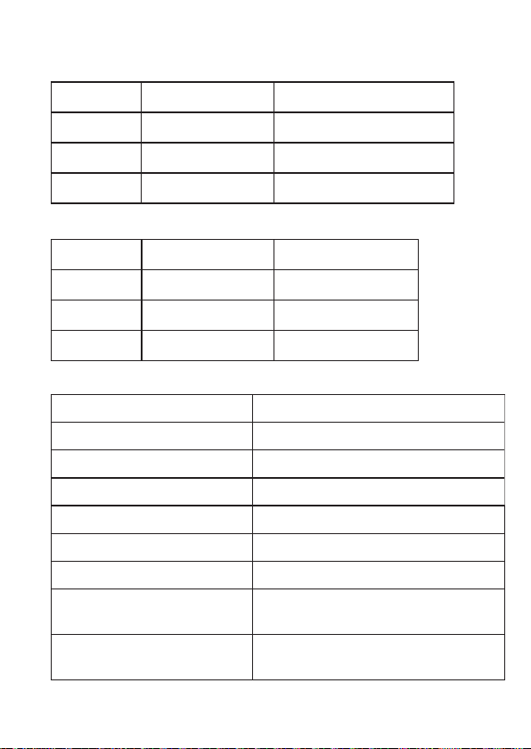
Rated enviromental conditions:●
(1) Indoor use.
(2) Installation Category I
(3) Pollution Degree 2.
(4) Altitude up to 2000 meters.
(5) Relative humidity 80% max.
(6) Ambient temperature 0~40℃.
Features:3.
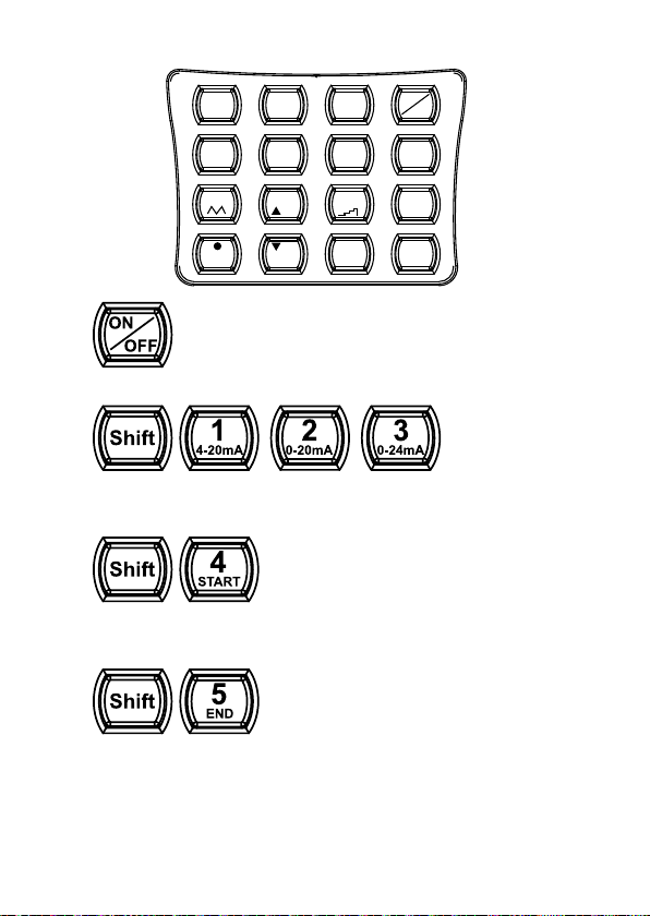
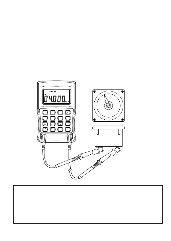
(1) 4-20mA (1KΩ load, 24V Loop Supply)
(2) 0.025% Basic Accuracy
(3) Simple Operation Interface
(4) Auto Ramp and Step Functions
(5) 0-20mA, 0-24mA selectable
(6) Incremental percentage setting: 0-100%
(7) Warning beeper when output is open
(8) 0-24 V output

-2-
Specication (254. ℃±5℃≤85%R.H.)
DC CURRENT (1kΩ Max Load, 24v Loop Supply)
RANGE RESOLUTION ACCURACY
0-4mA 1uA ±0.025%±10uA
4-20mA 1uA ±0.025%±5uA
20-24mA 1uA ±0.025%±5uA
DC VOLTAGE
RANGE RESOLUTION ACCURACY
0-4V 1mV ±0.05%±10mV
4-20V 1mV ±0.05%±5mV
20-24V 1mV ±0.05%±5mV
GENERAL
Power Consumption 150mA at 24V 1kΩ load
Operating Temperature 0º C - 50º C
Operating Humidity ≤80% R.H.
Storage Temperature -10º C - 60º C
Storage Humidity ≤85% R.H.
Power Source 9V x 1 alkaline battery
Dimensions 160 (L) x 100 (W) x 38 (D) mm
Weight Approx. 350g (battery includ-
ed)
Accessories DC adapter, pouch, battery,
instruction manual

-3-
Panel Description5.
1.LCD Display 6.ENTER Button
2.ON/OFF Button 7.Numerical & Function Keypad
3.Shift Button 8.DC Adaptor Input Socket
4.Voltage Button 9.Stand
5.Current Button 10.Output Terminal
4-20mA LOOP CALIBRATOR
123
4-20mA
4
7 8
0
9V
I
START 5
END
%
%
-+
6
SEC.
ENTER
Shift
0-20mA 0-24mA
ON
OFF
%
1.
7.
6.
2.
8.
9.
3.
4.
5.
10.

-4-
Display6.
1.mVA: Units
2.0-20mA: Output Range of mA
3.%: Percentage
4. : Ramp
5. : STEP
6.OL: Overload, output open
7.SHIFT:SHIFT functions
8. : low Battery
1.
2. 3.
4.
5.
6.
7.8.

-5-
Functions7.
Power ON/OFFa.
Press the SHIFT button and select the desired mAb.
range by pressing one of these three buttons.
Press the SHIFT button then press START (#4) buttonc.
to begin Auto Ramp Function.
Press the SHIFT button then press the END (#5)d.
button to stop Auto Ramp Function.
123
4-20mA
4
7 8
0
9V
I
START 5
END
%
%
6
SEC.
ENTER
Shift
0-20mA 0-24mA
ON
OFF
%

-6-
Press the SHIFT button then press the SEC. (#6)e.
button to enter the duration in seconds for Auto Ramp
Function.
Press the SHIFT button then press this button (#7)f.
to begin Auto Ramp Function. Press again to end Auto
Ramp Function.
Press the SHIFT button then press the % button tog.
select the percentage range.
After the percentage range has been entered,use
these / buttons to increase or decrease the
percentage incrementally.
Press the SHIFT button then press this button (#9) toh.
start the STEP function. Press again to stop the function.

-7-
Press ENTER button to accept entry of numbers.i.
Press the SHIFT button then press V to change toj.
Voltage setting.
Press the SHIFT button then press the I button tok.
return to mA (current) setting.

-8-
Operating Instruction8.
mA Output Selection:A.
Insert the test leads to the black and red terminals1.
on the calibrator accordingly.
Connect the leads to the device under test.2.
Press the On/Off button.3.
The device automatically defaults on the 4-20mA4.
range. Press the SHIFT button and select one of
the desired range buttons: 1, 2 or 3. The selected
range will be displayed on the LCD.
NOTE: A maximum of 5 digits can be entered. If < 5 digits
(1 to 4) are entered, you must press the ENTER button
to accept end of entry. If > 5 digits, the calibrator will
automatically accept the entry and the output specied
current.
4-20mA LOOP CALIBRATOR
123
4-20mA
4
7 8
0
9V
I
START 5
END
%
%
-+
6
SEC.
ENTER
Shift
0-20mA 0-24mA
ON
OFF
%
4.000mA

-9-
4-20mA LOOP CALIBRATOR
123
4-20mA
4
7 8
0
9V
I
START 5
END
%
%
-+
6
SEC.
ENTER
Shift
0-20mA 0-24mA
ON
OFF
%
4-20mA LOOP CALIBRATOR
123
4-20mA
4
7 8
0
9V
I
START 5
END
%
%
-+
6
SEC.
ENTER
Shift
0-20mA 0-24mA
ON
OFF
%
Enter a value less than 1
First, select the range 2 or 3. Press the % (decimal) button,
then enter the desired value followed by the enter button.
4-20mA LOOP CALIBRATOR
123
4-20mA
4
7 8
0
9V
I
START 5
END
%
%
-+
6
SEC.
ENTER
Shift
0-20mA 0-24mA
ON
OFF
%

-10-
Percentage (%) Input:B.
Press the SHIFT button and then the % button (No1.
decimal number. The % resolution is 1%).
Select the desired percentage and press ENTER2.
The percentage number will be displayed on the3.
upper right corner of the LCD.
The corresponding value is calculated based upon4.
the range selected:
4-20mA: 1%=0.16mA (start at 4mA)
0-20mA: 1%=0.2mA
0-24mA: 1%=0.24mA
Press SHIFT button to exit out of Percentage Input5.
mode. The percentage display at the upper left
corner of the LCD will disappear, but the value will
remain displayed on the LCD.
4-20mA LOOP CALIBRATOR
123
4-20mA
4
7 8
0
9V
I
START 5
END
%
%
-+
6
SEC.
ENTER
Shift
0-20mA 0-24mA
ON
OFF
%
4-20mA LOOP CALIBRATOR
123
4-20mA
4
7 8
0
9V
I
START 5
END
%
%
-+
6
SEC.
ENTER
Shift
0-20mA 0-24mA
ON
OFF
%

-11-
4-20mA LOOP CALIBRATOR
123
4-20mA
4
7 8
0
9V
I
START 5
END
%
%
-+
6
SEC.
ENTER
Shift
0-20mA 0-24mA
ON
OFF
%
4-20mA LOOP CALIBRATOR
123
4-20mA
4
7 8
0
9V
I
START 5
END
%
%
-+
6
SEC.
ENTER
Shift
0-20mA 0-24mA
ON
OFF
%

-12-
Adjusting the Percentage Up and Down:C.
After the % button has been selected (while still in
SHIFT mode), you may adjust the percentage up or
down by using the / buttons.
The minimum percentage range is 0%. The maximum
percentage range is 100%. If the percentage exceeds
the minimum or maximum percentage, the percentage
will remain in the previous percentage adjustment.
Example 1: Adjusting the Percentage Up and Down
(25%)
25%->50%->75%->100%->75%->50%->25%->0%-
>25%
Example 2: Adjusting the Percentage Up and Down
(30%)
30%->60%->90%->60%->30%->0%->30%
4-20mA LOOP CALIBRATOR
123
4-20mA
4
7 8
0
9V
I
START 5
END
%
%
-+
6
SEC.
ENTER
Shift
0-20mA 0-24mA
ON
OFF
%
4-20mA LOOP CALIBRATOR
123
4-20mA
4
7 8
0
9V
I
START 5
END
%
%
-+
6
SEC.
ENTER
Shift
0-20mA 0-24mA
ON
OFF
%

-13-
4-20mA LOOP CALIBRATOR
123
4-20mA
4
7 8
0
9V
I
START 5
END
%
%
-+
6
SEC.
ENTER
Shift
0-20mA 0-24mA
ON
OFF
%
4-20mA LOOP CALIBRATOR
123
4-20mA
4
7 8
0
9V
I
START 5
END
%
%
-+
6
SEC.
ENTER
Shift
0-20mA 0-24mA
ON
OFF
%

-14-
Auto Step Function:D.
Starting Auto Step Function
The default percentage is 25%. And the default1.
duration for Step is 4 seconds.
To begin Auto Step Function, press the SHIFT2.
button followed by the # 9 button. Calibrator
outputs 0% of the range for 4 seconds. Then it
will jump to 25%, displaying the output for another
4 seconds…then
75% (for 4 seconds)
100% (for 4 seconds)
75% (for 4 seconds)
25% (for 4 seconds)
0% (for 4 seconds)
25% (for 4 seconds)
Press the number 9 button to temporary stop the3.
Step function.
4-20mA LOOP CALIBRATOR
123
4-20mA
4
7 8
0
9V
I
START 5
END
%
%
-+
6
SEC.
ENTER
Shift
0-20mA 0-24mA
ON
OFF
%

-15-
Step Size (%)
1. Press the SHIFT button and then the % button
to enter the percentage value.
2. Then press ENTER.
Example:15%
15% (for 4 seconds)
30% (for 4 seconds)
45% (for 4 seconds)
60% (for 4 seconds)
75% (for 4 seconds)
90% (for 4 seconds)
Duration
1. Press the SHIFT button and then the SEC. (#6)
button to enter the value in seconds.
2. Then press ENTER.
75% (for x seconds)
100% (for x seconds)
75% (for x seconds)
25% (for x seconds)
0% (for x seconds)
25% (for x seconds)
4-20mA LOOP CALIBRATOR
123
4-20mA
4
7 8
0
9V
I
START 5
END
%
%
-+
6
SEC.
ENTER
Shift
0-20mA 0-24mA
ON
OFF
%
4-20mA LOOP CALIBRATOR
123
4-20mA
4
7 8
0
9V
I
START 5
END
%
%
-+
6
SEC.
ENTER
Shift
0-20mA 0-24mA
ON
OFF
%

-16-
Auto Ramp Function:E.
The following is the default setup for Auto Ramp
Function:
RANGE START END DURATION
4-20mA 4mA 20mA 4 seconds
0-20mA 0mA 20mA 4 seconds
0-24mA 0mA 24mA 4 seconds
Begin the Ramp Function:
1. Press the SHIFT button followed by buttons 1, 2, or
3 for the desired range.
2. Prepare the desired START, END and DURATION
values. See instructions for each on page 18.
below.
3. After setting the START, END and DURATION
values, press the SHIFT button followed by the
AUTO RAMP (#7) button.
4. Press the #7 to restart again.
5. To return to the regular output mode, press the
SHIFT button again when the ramp function has
stopped.
Example:
RANGE START END DURATION
0-20mA 2mA 8mA 5 seconds

-17-
4-20mA LOOP CALIBRATOR
123
4-20mA
4
7 8
0
9V
I
START 5
END
%
%
-+
6
SEC.
ENTER
Shift
0-20mA 0-24mA
ON
OFF
%
4-20mA LOOP CALIBRATOR
123
4-20mA
4
7 8
0
9V
I
START 5
END
%
%
-+
6
SEC.
ENTER
Shift
0-20mA 0-24mA
ON
OFF
%
4-20mA LOOP CALIBRATOR
123
4-20mA
4
7 8
0
9V
I
START 5
END
%
%
-+
6
SEC.
ENTER
Shift
0-20mA 0-24mA
ON
OFF
%
4-20mA LOOP CALIBRATOR
123
4-20mA
4
7 8
0
9V
I
START 5
END
%
%
-+
6
SEC.
ENTER
Shift
0-20mA 0-24mA
ON
OFF
%
4-20mA LOOP CALIBRATOR
123
4-20mA
4
7 8
0
9V
I
START 5
END
%
%
-+
6
SEC.
ENTER
Shift
0-20mA 0-24mA
ON
OFF
%

-18-
Establishing the START, END and DURATION of theF.
Ramp Function:
START
1. Press the SHIFT button, then the START (#4)
button. STR will be displayed at the upper right
corner of the LCD.
2. Enter the desired value and press the ENTER
button.
END
1. Press the SHIFT button, then the END (#5) button.
End will be displayed at the upper right corner of
the LCD.
2. Enter the desired value and press the ENTER
button.
DURATION
1. Press the SHIFT button, then the SEC. (#6) button.
SEC will be displayed at the upper right corner of
the LCD.
2. Enter the desired value and press the ENTER
button. The range for duration is from 1 to 2000
seconds.
NOTE: Users should set an appropriate value for the
duration of ramp function. For a full range ramp, users
should enter at least 4 seconds for the duration.
Table of contents
Other CABAC Test Equipment manuals
Popular Test Equipment manuals by other brands

Grace
Grace SafeSide P-S10S21-M2RX Series installation guide

Bender
Bender EDS440-LAF-4 manual

Bohle
Bohle MERLIN TGi BO 51 646 01 instruction manual

DANPHONE
DANPHONE Futronic GMDSS-AIS-SART user manual

FLO-DYNAMICS
FLO-DYNAMICS Test-Quick LPLT-100 Operation manual

Tektronix
Tektronix MTS400 Series Quick start user manual