Pite BT3915 User manual

BT3915 Battery Tester
User Manual
P-141106-V1.8

2
Catalogue
1. INTRODUCTION ...................................................................................................................................................... 3
1.1 SAFETY INFORMATION ............................................................................................................................................ 3
1.2 OPERATING PRECAUTIONS ...................................................................................................................................... 3
2. ABOUT BT3915 ....................................................................................................................................................... 4
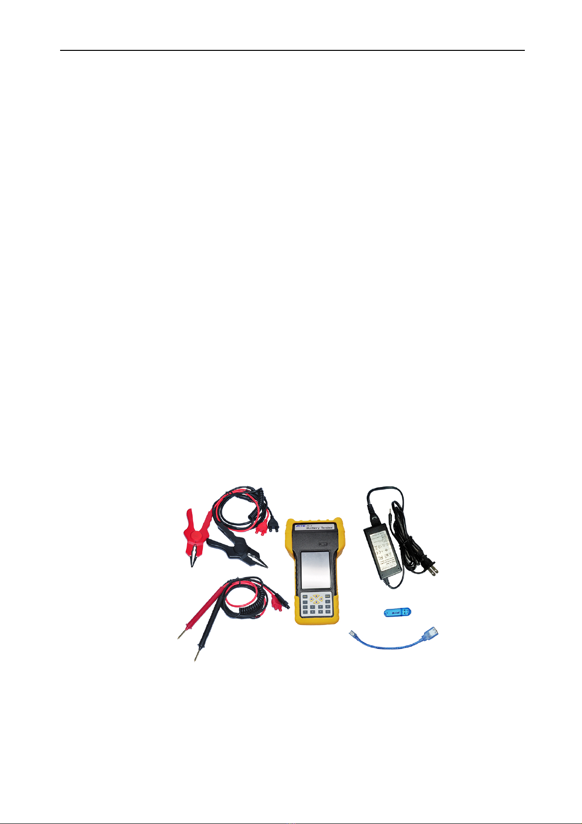
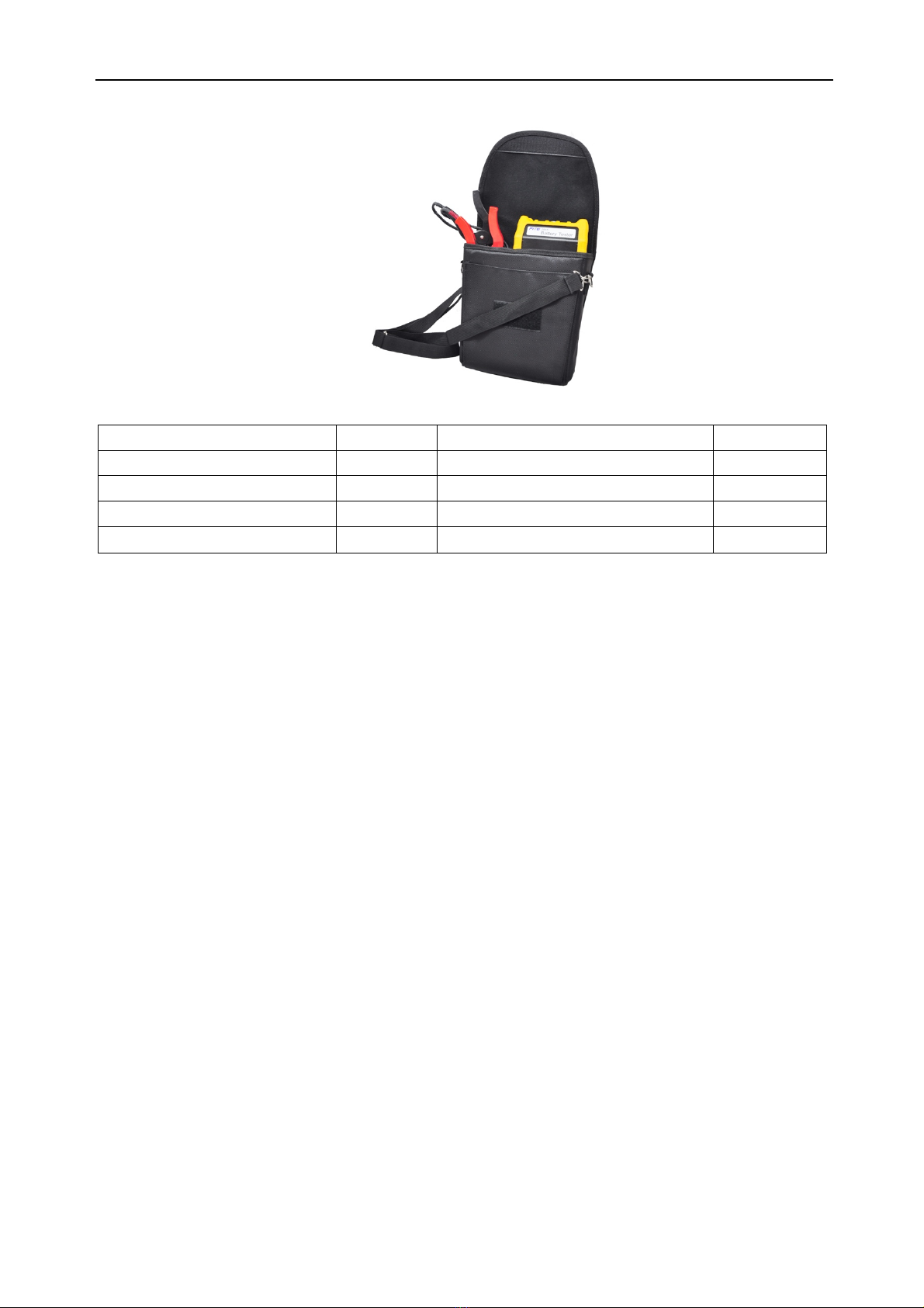
2.1 ACCESSORIES .......................................................................................................................................................... 4
2.2 APPLICATION ......................................................................................................................................................... 5
2.3 FEATURE ................................................................................................................................................................. 5
2.4 TECHNICAL PARAMETER ...................................................................................................................................... 6
3. OPERATION .............................................................................................................................................................. 6
3.1 MEASUREMENT PREPARATION ................................................................................................................................ 6
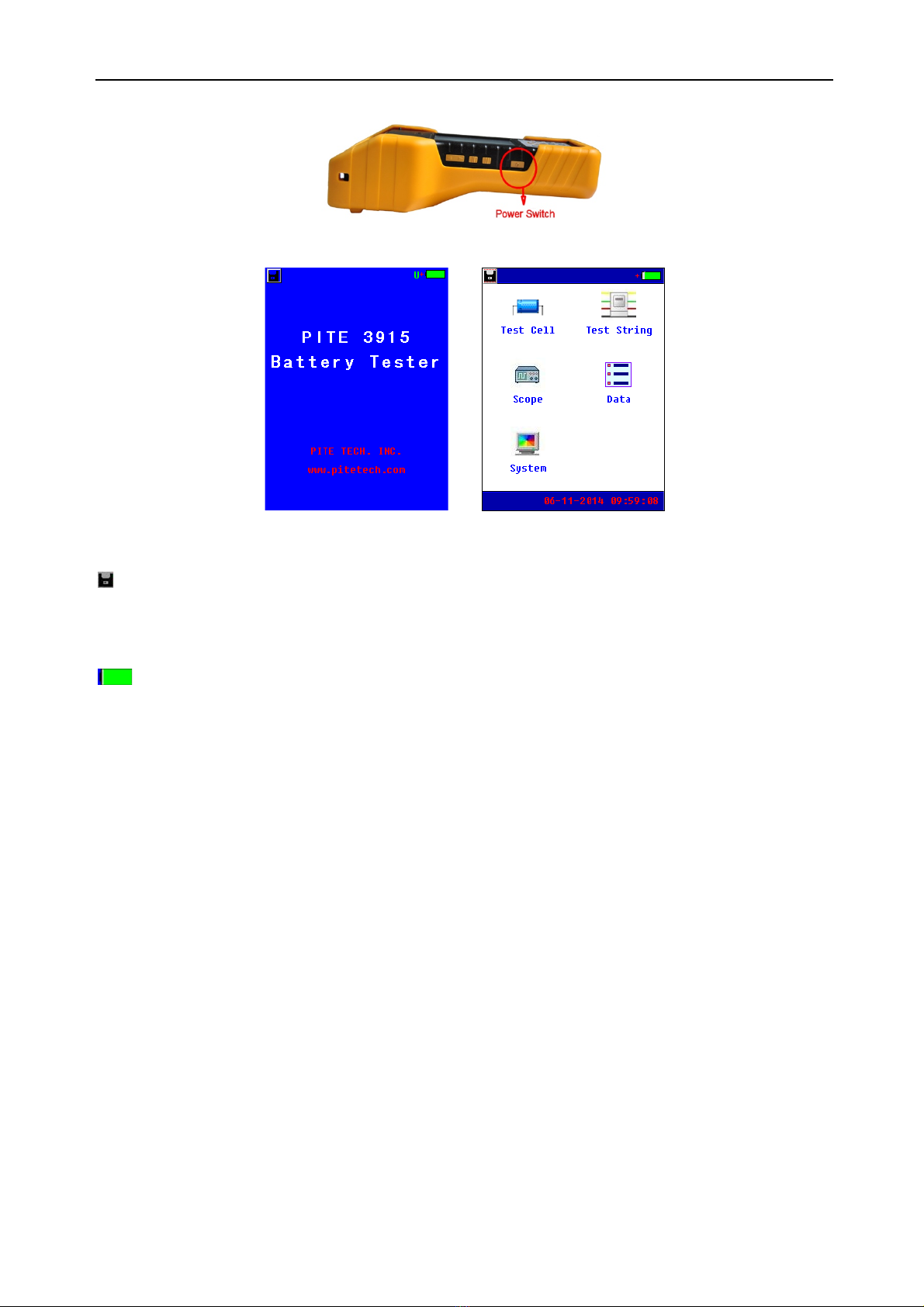
3.1.1 Main Unit Structure and Operation .......................................................................................................... 6
3.1.2 Wire Connection .......................................................................................................................................... 7
3.1.3 Power On ..................................................................................................................................................... 7
3.1.4 About Reference Values ............................................................................................................................ 8
3.2 MEASUREMENT ..................................................................................................................................................... 9
3.2.1 Test for Single Cell ................................................................................................................................... 9
3.2.2 Test for Battery String ............................................................................................................................ 11
3.3 DATA MANAGEMENT ........................................................................................................................................... 13
3.4 SYSTEM MANAGEMENT ...................................................................................................................................... 15
3.4.1 Instrument Calibration .............................................................................................................................. 15
3.4.2 Time Setting ............................................................................................................................................... 16
3.4.3 System Update .......................................................................................................................................... 17
3.4.4 Version Information ................................................................................................................................... 17
4. DATAVIEW SOFTWARE .................................................................................................................................. 17
4.1 SOFTWARE INSTALLATION/UNINSTALL ................................................................................................................. 18
4.1.1 Software Installation ................................................................................................................................. 18
4.1.2 Software uninstall ..................................................................................................................................... 19
4.2 SOFTWARE OPERATION ......................................................................................................................................... 19
4.2.1 Import Data ................................................................................................................................................ 19
4.2.2 View & Delete Data .................................................................................................................................. 20
4.3 HELP ..................................................................................................................................................................... 24
4.4 HOT KEY .............................................................................................................................................................. 25
5. SERVICE AND MAINTENANCE ......................................................................................................................... 25
5.1 CLEANING ............................................................................................................................................................. 25
5.2 STORAGE .............................................................................................................................................................. 25
5.3 BAT T E RY M AI N T E N A N C E ....................................................................................................................................... 25
6. FAQ ........................................................................................................................................................................... 25
7. APPENDIX ............................................................................................................................................................... 26

3
1. INTRODUCTION
This Users Manual gives full information on how to use BT3915 Battery Tester (hereinafter called
“Tester”) safely and effectively. Please read the manual carefully so as to obtain maximal performance
of the Tester.
Warning: Read this manual completely before connecting and powering on the Tester to avoid
possible damage caused by improper use of this instrument.
1.1 Safety Information
For your protection, please read this safety information completely before operating the activator.
Carefully observe all warnings, precautions and instructions.
WARNING: Servicing described in this manual is to be done only by qualified personnel. To avoid
electric shock, do not service the instrument unless you are qualified to do so.
DANGER
Safety testing has been done on this instrument thoroughly
before shipment. However, mishandling during use could result
in injury or other bad consequences, as well as damage to the
instrument. Make sure that you understand the instructions and
precautions in the manual before use. We disclaim any
responsibility for accidents or injuries not resulted directly from
instrument defects.
Safety Symbols
Description of symbols used in this manual.
DANGER
Indicates correct operation to prevent an extreme hazard that
could result in serious injury or other bad consequences to
users.
WARNING
Indicates correct operation to prevent a significant hazard that
could result in serious injury or other bad consequences to
users.
CAUTION
Indicates correct operation to prevent possible injury to users
or damage to the instrument.
NOTE
Indicates advisory items related to performance or correct
operation of the instrument.
1.2 Operating Precautions
Safety information
1) BT3915 is widely used in power utility, telecom machine room, industrial production management
and the alike for testing of resistance and voltage of standby batteries. It may somehow be
dangerous during operation. Only qualified technicians or specialized trained personnel are

4
recommended to use it.
2) This device includes a LCD touch screen. Please avoid crashing, moisture, hard scratching or any
other operation that may damage the screen.
3) This device includes a rechargeable Lithium battery. Please charge it only with ’s battery charger.
The rechargeable batteries may get heat during charging. User should take care when taking out
batteries after charging. Disconnect the charging unit from the power supply when it is not in use.
4) Do not try to uninstall the device by yourself. If necessary, please contact for some helpful
assistance.
Disclaimer
will not be liable to any accessories/product malfunction or damage, or any personal harm caused
by any misuse of product, illegal purpose of using this device or any other way not described in this
user manual.
2. ABOUT BT3915
BT3915 is a new generation of battery tester with touch-screen. It is strictly designed to evaluate and
maintain all stationary power systems including Uninterruptible Power System.
Via accurate testing of resistance and voltage, it gives an indication of battery capacity and technical
status. The measurement data can be read on the instrument display directly. And it can also be
uploaded to PC simply by using the USB drive. With the analyzing software, you could not only keep a
record of the testing result but also have detailed analyzing for the status of batteries in different
testing conditions.
2.1 Accessories
After receiving the instrument, make sure you have all the following parts.
Portable bag for convenient carrying and field testing.

5
Detailed packing list as blow:
Name
Number
Name
Number
Portable bag
1
Tes tin g clamp (pair)
1
Main unit
1
Power adaptor
1
USB converter
1
USB drive
1
User manual
1
Pin type probe(pair, Optional)
1
2.2 Application
BT3915 Battery Tester is widely used in the following areas:
¨ Tel ec om: Ce ntr al Office, data processing centers and Remote Sites
¨ Power Utility: Switchgear, Power Station and Power Plant
¨ Financial Institutions: Corporate Data Centers
¨ Petrochemical: Process Control systems
¨ Offshore platforms
¨ Government: Local and regional
¨ Tax a nd Rev enue Processing Centers
¨ Homeland Security, Schools, Army and Navy
¨ Air force Facilities, Fire and Police Agencies
¨ Hospital UPS system
¨ Electrical vehicle suppliers
¨ SLA battery manufactures
2.3 Feature
¨ Wide test range: 5~6000Ah, compatible for single cell of 1.2V, 2V, 6V and 12V
¨ Smart and portable hand-held device, rugged and easy-to-go
¨ Colorful touch screen with optional operations of keyboard
¨ Simultaneously test for voltage, resistance and estimated capacity of batteries
¨ Online measurement, no need to remove battery and string from its system for testing, safe and
convenient
¨ Fast testing for battery and string in seconds with testing data auto saving
¨ Strong anti-interference in high current with stable and accurate performance
¨ Tes tin g f req uen cy lo wer t ha n10 Hz, effectively avoid interference from capacitive resistance of

6
battery itself
¨ Direct USB drive for software update and data transfer to PC for further analyzing
¨ Powerful PC management software, convenient for data storage and analyzing
¨ Big memory for testing data storage of more than 3000 cells
¨ Buzzer Alarm Function and over voltage protection, secure to use
¨ Auto-calibration function before testing, enhancing the testing accuracy
¨ Retest and compensation function: any faulty operation or omission could be retested simply with
one click
¨ Referenced data inside memory for the comparison of your test, and self-defined reference values
are available
2.4 Technical Parameter
Items
Parameters
Tes t r an g e
Resistance: 0.000mΩ~100mΩ
Voltage: 0.000V~150V
Tes t r es o lu tio n
Resistance: 0.001mΩ
Voltage: 1mV
Tes t a ccu ra c y
Resistance: ±2.0%rdg±6dgt
Voltage: ±0.2%rdg±6dgt
LCD display
240*320 pixel 3.5" TFT touch screen
Dimension
210mm*110mm*60mm
Weight
0.5kg
Memory
16M bytes,FLASH
Power supply
Rechageable Li-ion battery, more than 5 hours working time after full
charge
Power adapter
AC100V~240V/DC8.4V-1A
Communication interface
USB
* 16V-220V is for over voltage protection.
3. OPERATION
3.1 Measurement Preparation
3.1.1 Main Unit Structure and Operation
Below are the pictures for the main unit:
Back Side

7
Bottom To p
Fig 3.1.1
Operation of touch-screen
Click on each menu to highlight it and click it again to carry out each function. Click “Back” to return to
the upper menu and click “Home” to return to the starting screen.
Operation of keyboard:
Keyboard operation has the same effect with touch-screen operation. Press each arrow key “←”, “→”,
“↑” and “↓” to highlight each menu and press Enter to activate it. And key Esc is for going back to
upper menu.
3.1.2 Wire Connection
Before measurement, please first connect the testing clip with main unit and fix the screw like Fig
3.1.2.1. Then clamp the black clip with the negative polar of battery and the red clip with positive.
NOTE:
1) To e nha nce t he m eas ure men t ac cur ac y, please try to clamp the clips around the posts of
battery. Rust or any insulating material (e.g. glue) around the posts will increase the
resistance. Therefore, please try to avoid these causes before connecting the clips.
2) Measurement of 3918 is based on 4-point measurement. Each clamp has two metal points
that are connected with the battery posts during measurement. This is same to the pin type
probe. So each time when you use the pin probe for measurement, make sure that all the four
pins on the pin probe should be connected with the battery posts well.
Fig 3.1.2.1 Fig 3.1.2.2
3.1.3 Power On
Switch on the power on/off button indicated in Fig 3.1.3.1, you will see the starting screen as Fig
3.1.3.2. Click any point of screen to view the main menu like Fig 3.1.3.3:

8
Fig 3.1.3.1
Fig 3.1.3.2 Fig 3.1.3.3
About screen:
: This icon is for screenshot. Connect the USB drive with bottom of the main unit with USB converter,
highlight this icon, click it again and wait for a little while, the current screen will be snapped in the USB
drive.
06-11-2014 09:59:08: indicates the current time which is predefined in 3.4.2 Time Setting.
: This icon indicates the status of Li-ion battery inside main unit. When it is full green, it is full
charged. If it is blank, it indicates that battery is low. Please connect with the power adaptor timely for
charging.
U: When this letter turns green, it indicates the USB drive is well connected with main unit.
3.1.4 About Reference Values
BT3915 has pre-installed reference conductance for some common battery types. These values are
average conductance values got from samples of strong battery strings similar in condition and age of
usage. Generally, a sample of 30 new or healthy batteries are tested to obtain a value representative
of a new online battery 90 days after installation. By comparison, the differences between test results
and reference values will help you determine the string capacity and health status for further solutions.
Differences may reflect how a string was treated, installed, or maintained.
How to specify your reference values?
Reference values in BT3915 menu may not universally fit the batteries that you are testing. Therefore,
you are recommended to specify your own reference values. You have the following options to set
your reference value:
A. Consult to your document from battery manufacturer for the reference values for the batteries that
you are testing.
B. Tes t the ba tt e ri es in th e st r in g and u se t he lowest conductance under correct way of test for
reference value. For cells ranking in the string, please refer to String summary in 3.3 Data
Management.

9
C. Use the average conductance of the string as reference value. This is only used for measurement
of battery string. For detailed setting, please refer to “Set average value as reference” in section
3.2.2 Test for Battery String.
Indications of Battery Condition
Below is the definition of the testing result for battery and battery string.
Indication
Reference
Guide
Good
0.8≤R%<1.15
-20%≤Measured resistance fluctuation<15%
Pass
1.15≤R%<1.5
15%≤Measured resistance fluctuation <50%
Warn
1.5≤R%<2.0
50%≤Measured resistance fluctuation <200%
Fail
2.0≤R%
Measured resistance fluctuation>200%
Abnormal
Vm<0.9 OR Vm>1.2 or
R%<0.8
Battery is Abnormal
Vm<0.9 OR Vm>1.2 or
R%<0.8
NOTE: You could also see reference values in Appendix of this manual.
3.2 Measurement
3.2.1 Test for Single Cell
This is for testing single cell. To do this, you will need to set the parameter of the cell before
measurement. If you have several blocks of batteries of the same rating (e.g. 2V, 100Ah), you are
suggested to use “string test” (see 3.2.2) which will be much more time-saving and convenient for data
management in PC software.
Select “Test Cell” in the menu to enter the screen for parameter setting. (See Fig 3.2.1.1).
Fig 3.2.1.1 Fig 3.2.1.2
Use main unit keyboard or mini keyboard on screen for number input.
Tot all y th er e are 5 options for single cell voltage: 1.2V, 2V, 6V, 12V and self-defined. Please click the
option of “Voltage” to view each one (Fig 3.2.1.1). As voltage changes, cell rating will be changed
accordingly. Click the box or use arrow keys to select the cell type that you will test. Reference
resistance will be changed to fit each cell type.

10
Cell number is self-defined to distinguish from each other. This could be viewed in data management.
After the setting, click the button Start at right bottom to carry out the test.
Tes tin g r esu lt wi l l d is play in seconds like Fig 3.2.1.7. If you need to retest it, click the button Retest.
Click Save (in Fig 3.2.1.2) to save the testing result, or disconnect the testing clips from battery and
testing result will be automatically saved.
NOTE: As mentioned in 3.1.2 Wire connection, testing result may vary a little due to different way of
connection between testing clips and battery posts. Therefore, if testing result varies in different time,
please refer to the lower value.
Specify Battery Type & Reference Value
If you could not find the exact type of battery that you want to test, or you want to specify your own
reference resistance, you could self-define the parameter.
1) Specify battery type
If you have battery that has non-standard voltage type (e.g. 4V 100Ah), you could add this type. To do
this, please select “Defined” in the box of “Voltage”, then click Set Para at the bottom, input the
parameters required and click Add to save the setting (e.g. refer to images from Fig 3.2.1.3 to Fig
3.2.1.5). Maximally you could set 10 different voltage types.
2) Specify reference value
If you would like to set different resistance reference or cell type under the same battery voltage,
please first select voltage rating and then click the button Set Para to add these information.
Maximally you could add 10 different cell types under each battery voltage. Screen in Fig 3.2.1.6 and
Fig 3.2.1.7 are for your reference.
Fig 3.2.1.3 Fig 3.2.1.4

11
Fig 3.2.1.5 Fig 3.2.1.6 Fig 3.2.1.7
To del et e de fin ed va lue s, pl ea se cli ck Set Para in the menu and click Delete. This step will delete all
the customized value that you have set before.
3.2.2 Test for Battery String
This function is for testing batteries of the same type one by one in a string. Maximally it could record
up to 256 sites. Each site could record up to 256 strings. And one string could test up to 256 cells
based on its setting. When all the batteries are of the same type, you just need to set the parameter at
the beginning and the whole measurement process could be done in a very short time.
To ge t s tar ted, click “Test String” in main menu to go to the next step for parameter setting. Select
battery rating in the same way like single cell measurement. Setting of user-defined data is also in the
same way.
Fig. 3.2.2.1 Fig. 3.2.2.2

12
Fig. 3.2.2.3 Fig. 3.2.2.4 Fig. 3.2.2.5
“Site Name”: user-defined, input the number or letter of site for convenient data recording
“String Name”: user-defined to distinguish it from other strings
“No. of Cell” indicates the total number of cells in one string.
If you need to specify your own reference value, do in the same way like the setting in single cell test
(Fig. 3.2.2.2). After the above settings, click Start to go to the next step. “Test No.” (Fig. 3.2.2.3)
indicates the cell to begin the test in the string. For example, if total cells are 3 and “Test No.” 1, that
means it will begin the test from the first (No. 1) cell.
NOTE: If you need to retest certain cell (e.g. first cell in a string of 3) or cells after the whole string test,
just input the cell number (in Fig. 3.2.2.3) to begin the test. In DataView software, new testing result
will automatically overwrite the previous record.
After the above setting, click Start to begin the measurement. Testing result of the first cell will
displayed like Fig 3.2.2.4 when you hear the sound “Beep”. Then disconnect the testing clips, testing
data of the first cell will be automatically saved with another “Beep”. Then clamp the testing clips on
the next cell, wait for a few seconds before the testing automatically begins. Do in the same way until
the last cell.
During string testing, you could just put the tester in the carrying bag after clicking the button Start.
This is very convenient for testing and only one personnel is needed to handle string testing in a short
time.
When measurement of all batteries in the same string are finished, you will hear the longer sound
Beep and get the testing result as Fig. 3.2.2.5. String summary with all batteries ranking and average
values will be displayed. To review detailed data, please refer to 3.3 Data Management.
Set average value as reference:
This function is only for battery string. In this measurement, there is no reference value at the
time of setting. After the testing of the whole string, it will automatically take the average
resistance as the reference value of the whole string. Please do as below:
In the exemplified screen of Fig. 3.2.2.1, you just select the voltage type, click the button Set,
finish the setting of other parameter as usual and continue the measurement. For

13
exemplified screen of measurement result, please refer to 3.3 Data Management.
In measurement of 1.2V Ni-cd batteries, currently you could only set average as reference.
3.2.3 Test of Oscilloscope
This function could have a simple test for battery voltage. Select “Oscilloscope” in main menu and
you will see the screen as below (see Fig 3.2.3):
Fig. 3.2.3
“1V” indicates the voltage scale on the vertical axle.
“100uS” indicates time on the horizontal axle.
Both numbers are changeable for different view.
3.3 Data Management
Tes tin g da ta f or s i ng le c ell a n d battery string are saved in main unit memory as tests are finished.
Maximally the Internal memory could save testing data for 3000 cells. Before space is full, please
transfer the data timely to PC by using the USB drive and USB converter.
For management, click “Data” in the main menu, and then go to the following screen:
Fig. 3.3.1 Fig. 3.3.2 Fig. 3.3.3 cell result
Select the displaying for single cell or string on the top of the screen.
Tes tin g d at a li ke nam e, te s ti ng time and size will be displayed. Other buttons have functions as below:
Open: Click this button to view the testing result as Fig. 3.3.2 and Fig 3.3.3.
Up / down: paging up or down.
Save: Select relevant item and click this button to save the testing result in the USB drive. Before this

14
operation, make sure that the USB drive is well connected.
Anal : Click this button to have a string summary with all batteries ranking and average values will be
displayed.
Delete: Select the desired item and click this button to delete the record.
Format: It is used to format all testing records.
NOTE: Please make sure that you have kept them properly before deleting or formatting the records.
Once deleted or formatted, the data could not be recovered.
Fig. 3.3.4 Fig. 3.3.5
Fig. 3.3.6 All cells Fig. 3.3.7 Voltage ranking Fig. 3.3.8 Resistance ranking
String Summary
String summary will help you judge the general health status of batteries in the same series.
Reference values could be picked up from the summary.
To v ie w s t ri ng s um m ar y, p lea se o pe n r e la tiv e r eco rd of st rin g (e.g. Fig. 3.3.4) and click Anal to view
the string test summary. It will list average resistance, average voltage, 8 cells with highest resistance
and 8 cells with lowest voltage in the whole string (Fig.3.3.5). Click Order to further ranking of voltage
and resistance for the whole string like Fig. 3.3.6- Fig. 3.3.8. Voltage will be ranked from low to high,
and resistance will be ranked from high to low.
NOTE:
l To en ha n ce d te s ti ng acc ura cy, the hig hes t an d lo wes t va lu e s in th e battery string are excluded in
the calculation of average resistance and voltage.
l If there are no more than 8 cells in the string that you have tested, all cells will be listed in highest

15
resistance and lowest voltage.
l Average resistance and lowest resistance in the string could be used as self-defined reference
value.
3.4 System Management
Click “System” in the main menu, and then you will see the following screen for system management
(see Fig 3.4). For detailed instruction, please check the text below.
Fig. 3.4
3.4.1 Instrument Calibration
This section only includes basic information for calibration of the unit. For the whole process of
calibration, you will require some specific facilities and a more detailed instruction from . Please
contact your supplier if you need this.
3.4.1.1 Zero Calibration
Zero calibration is used for more reliable measurements by way of adjusting the zero values of
resistance-range and voltage-range. Before calibration, please remove the connection with any battery.
To b egi n i t o n s cre en, c li ck “ Zero-Cali” and go to the next screen as below (see Fig 3.4.4.1.1). Just
click the button “Calibrate” and wait for a few seconds until the screen displays “Calibration Done!”
Fig 3.4.4.1.1
3.4.1.2 Voltage Calibration
Voltage Calibration is used to calibrate voltage of a single cell. This testing requires connection with
cells. Click “Volt-Cali” to enter into the screen of calibration. Select the cell type for the first cell for

16
testing, input the actual value in “Real V1” and click the button Cali. After the first cell is calibrated,
input the actual value for the second and click Cali as well. If you need to calibrate other cell type,
select it on the top “Range” and repeat the same operation. For more detailed instruction, please
contact sales representative.
Fig 3.4.4.1.2
3.4.1.3 Resistance Calibration
This function will require specific instrument and has been calibrated well in before delivered to you.
For more detailed instruction, please contact ’s sales representative.
3.4.1.4 Phasic Calibration
This function will require specific instrument and has been calibrated well in before it is delivered to
you. If you really need it, please contact your supplier for detailed instruction.
3.4.1.5 Save parameter setting
After all the above calibrations, please do not forget to save new parameters before the main unit is
turned off. To do this, click “Save Para” and input the password “12345678” (Fig 3.4.1.4). If password
is correct, you will see the indication: “Saved!”
Fig 3.4.1.4 Fig 3.4.2
3.4.2 Time Setting
Click “Time” for data and time setting. The Screen will be seen as below (see Fig 3.4.2). The first line
is for date setting and second line for time. After the setting, click OK to save the change.

17
3.4.3 System Update
BT3915 enjoys free software update from TECH. INC. The update is done by direct connection with
USB drive. You have two optional ways to update it:
1. Save the new software in the root directory of USB drive, connect the USB drive with main unit,
click “Update” under “System” and select OK (see Fig 3.4.3) You will see the process for update
on screen. After update is done, screen will automatically to the starting screen.
2. Connect the USB drive with main unit and restart the unit. You will see the process screen for
update. After update is done, screen will automatically to the stating screen.
Both ways have the same effect for update.
Fig 3.4.3
3.4.4 Version Information
Software version will change as update is done. To view the current version and serial number of the
tester, click “Version” and you will see screen as below: (see Fig 3.4.5)
Fig 3.4.4
4. DATAVIEW SOFTWARE
All testing data are saved in BT3915 main unit and it could be transferred to computer for data view.
The following software should be well installed to enable the data analyzing. This software will help
you know battery health status comprehensively. Application Software is included in the attached USB

18
drive. This software will comply with Operation Systems of Windows XP and Win 7.
4.1 Software Installation/Uninstall
4.1.1 Software Installation
1) Start your computer
2) Stop all applications running in the computer (recommended).
3) Connect the USB with computer.
4) Find installation folder and double click the file named “BT3915 Battery Tester Data View
setup.exe” to start the installation.
Installation screens will be as below.
Click Next to enter into the following screen:
Select “I agree to the terms of the license agreement” and click Next to enter the following step:

19
Change the setup root if necessary, click Next and you will come to this step:
Click Finish to complete the installation.
A window will pop up:” Installation completed. Do you want to start the management software?” Click
Yes to start it or No to close the window.
After installation is done, you will see the icon on the desktop. If you could not see it on desktop,
it can also be found in “Start” menu.
4.1.2 Software uninstall
To i nst al l th e so ft wa re , please follow these steps: Start à program à BT3915 Battery Tester Dada
View à Uninstall BT3915 Battery Tester Data View
4.2 Software Operation
This analyzing software is applied to BT3915 Battery Tester. Any generated report will be saved
automatically in the PC. You could save, delete or print testing data as per your need.
To s ta r t the software, double click the icon. And the main screen will pop up as Fig 4.2.a. You
will see the example data in the screen. This example could be deleted after you have imported your
data.
Fig 4.2.a
4.2.1 Import Data
All testing data are saved in BT3915 main unit and it could be transferred to computer via USB drive

20
for data analyzing. For proper operation, please use ’s USB drive only.
Click “File” and then “import”, a box will pop up like Fig 4.2.1.2
Fig 4.2.1.1
Fig 4.2.1.2
Select relevant testing data that are already saved in the PC and click Open to import.
NOTE: To im por t several files simultaneously, you could use keys like Ctrl or Shift for multi-selection
and click Open to import.
4.2.2 View & Delete Data
The imported data is showed on the main screen like Fig 4.2.2.a. It includes the information for site,
string test and cell test. Site number and string numbers are in accordance with the numbers
predefined in BT3915 main unit. All testing data will be grouped in different sites with string and cell
testing data below.
String includes string number, voltage, capacity, cell quantity and testing times.
Fig 4.2.2.a
Select site or string item and click right; you could carry out functions of Add, Modify and Delete. See
Table of contents
Other Pite Test Equipment manuals
Popular Test Equipment manuals by other brands

Center
Center 360 instruction manual

Elliott
Elliott 5373 Series Operating and maintenance instructions

IKONIX
IKONIX Associated Research Hypot 3805 quick start guide

Tektronix
Tektronix TDS3000B Series Operator training kit manual

Kurth Electronic
Kurth Electronic KE7200 operating instructions

LeCroy
LeCroy WaveJet 300A series manual