Würth PRO II LCD Quick guide

Originalbetriebsanleitung
Translation of the original operating instructions
Traduzione delle istruzioni di funzionamento originali
Traduction des instructions de service d’origine
Traducción del manual de instrucciones de servicio original
Tradução do original do manual de funcionamento
Vertaling van de originele gebruiksaanwijzing
Oversættelse af den originale betjeningsvejledning
Original driftsinstruks i oversettelse
Alkuperäiskäyttöohjeen käännös
Översättning av bruksanvisningens original
Μετάφραση της γνήσιας οδηγίας λειτουργίας
Orijinal işletim kılavuzunun çevirisi
Tłumaczenie oryginalnej instrukcji eksploatacji
Az eredeti üzemeltetési útmutató fordítása
Překlad originálního návodu k obsluze
Preklad originálneho návodu na obsluhu
Traducerea instrucţiunilor de exploatare originale
Prevod originalnega Navodila za uporabo
Превод на оригиналното ръководство за експлоатация
Originaalkasutusjuhendi koopia
Originalo naudojimosi instrukcijos vertimas
Ekspluatācijas instrukcijas oriģināla kopija
Перевод оригинала руководства по эксплуатации
Prevod originalnog uputstva za rad
Prijevod originalnih uputa za rad
MULTI-TESTER PRO II LCD
Art. 0715 53 175

2
DE ........................ 4 – 8
GB ........................ 9 – 13
IT ........................ 14 – 18
FR ........................ 19 – 23
ES ........................ 24 – 28
PT ........................ 29 – 33
NL ........................ 34 – 38
DK ........................ 39 – 43
NO ........................ 44 – 48
FI ........................ 49 – 53
SE ........................ 54 – 58
GR ........................ 59 – 63
TR ........................ 64 – 68
PL ........................ 69 – 73
HU ........................ 74 – 78
CZ ........................ 79 – 83
SK ........................ 84 – 88
RO ........................ 89 – 93
SI ........................ 94 – 98
BG ........................ 99 – 103
EE ........................ 104– 108
LT ........................ 109– 113
LV ........................ 114– 118
RU ........................ 119– 123
HR ........................ 124– 128
RS ........................ 129– 133

FI
RCD
LH
FI
RCD
3
I

4
Hinweis
Es ist verboten Veränderungen am
Gerät durchzuführen oder Zusatzge-
räte herzustellen. Solche Änderungen
können zu Personenschäden und
Fehlfunktionen führen.
■Reparaturen am Gerät dürfen nur von hierzu
beauftragten und geschulten Personen durch-
geführt werden. Hierbei stets die Originaler-
satzteile der Adolf Würth GmbH & Co. KG
verwenden. Damit wird sichergestellt, dass die
Sicherheit des Gerätes erhalten bleibt.
Der Spannungsprüfer muss
kurz vor dem Einsatz auf
Funktion geprüft werden.
Vergewissern Sie sich, dass
Messleitungen und Gerät in
einwandfreiem Zustand sind.
■Überprüfen Sie das Gerät an einer bekannten
Spannungsquelle , z. B. 230 V-Steckdose.
■Fällt hierbei die Anzeige einer oder mehrerer
Funktionen aus, darf das Gerät nicht mehr ver-
wendet werden und muss vom Fachpersonal
überprüft werden.
■Stromschlag kann zum Tod oder zu schweren
Verletzungen von Personen führen sowie eine
Gefährdung für die Funktion von Gegen-
ständen (z.B. die Beschädigung des Gerätes)
sein.
■Bitte beachten Sie die fünf Sicherheitsregeln:
1. Freischalten
2. Gegen Wiedereinschalten sichern
3. Spannungsfreiheit feststellen (Spannungs-
freiheit ist 2-polig festzustellen)
4. Erden und kurzschließen
5. Benachbarte unter Spannung stehende Tei-
le abdecken
■Richten Sie das LED-Licht nie direkt oder
indirekt durch reektierende Oberächen auf
das Auge.
■Vermeiden Sie einen Betrieb des Gerätes in
der Nähe von elektrischen Schweißgeräten,
Induktionsheizern und anderen elektromagne-
tischen Feldern.
■Nach abrupten Temperaturwechseln muss das
Gerät vor dem Gebrauch zur Stabilisierung
ca. 30 Minuten an die neue Umgebungstem-
peratur angepasst werden.
■Setzen Sie das Gerät nicht längere Zeit hohen
Temperaturen aus.
■Vermeiden Sie staubige und feuchte Umge-
bungsbedingungen.
■Messgeräte und Zubehör sind kein Spielzeug
und gehören nicht in Kinderhände!
■In gewerblichen Einrichtungen sind die
Unfallverhütungsvorschriften des Verbandes
der gewerblichen Berufsgenossenschaften
für elektrische Anlagen und Betriebsmittel zu
beachten.
■Gerät nur an den Handgrien anfassen, ver-
meiden Sie die Berührung der Prüfspitzen!
■Prüfungen auf Spannungsfreiheit immer nur
zweipolig durchführen!
Zu Ihrer Sicherheit
DE
Lesen Sie vor der ersten Benutzung
Ihres Gerätes diese Betriebsanleitung
und handeln Sie danach.
Bewahren Sie diese Betriebsanlei-
tung für späteren Gebrauch oder für
Nachbesitzer auf.
WARNUNG - Vor erster Inbetrieb-
nahme Sicherheitshinweise
unbedingt lesen!
Bei Nichtbeachtung der Betriebsanleitung und
der Sicherheitshinweise können Schäden am
Gerät und Gefahren für den Bediener und andere
Personen entstehen.
Bei Transportschaden sofort Händler informieren.
Sicherheitshinweise

5
Bestimmungsgemäße
Verwendung
Es können Gleichspannungen von 4 V bis 1400 V
und Wechselspannungen von 3 V bis 1000 V, Pola-
ritäts-, Drehfeldrichtungs- und Durchgangsprüfungen
bis 50 Ωsowie FI/RCD-Tests und Widerstandsmes-
sungen bis 1999 Ω durchgeführt werden. Dank
des drehbaren Abstandshalters ist bei Spannungs-
messungen eine Einhandbedienung möglich .
Multi-Tester Pro LCD ist durch die hohe Schutzart
(IP65) auch bei rauem Einsatz verwendbar.
Jeder darüber hinausgehende Gebrauch gilt als
nicht bestimmungsgemäß.
Für Schäden bei nicht bestimmungsgemä-
ßer Verwendung haftet der Benutzer.
Gerätekennwerte
Art. 0715 53 175
Anzeige Hintergrundbeleuchtetes
LC-Display
Nennspannungs-
bereich 3 ... 1000 V AC (TRMS)
+ -3 digits
4 ... 1400 V DC + -3 digits
Eingangsimpendanz 285 kΩ
Frequenzanzeige 0 ... 1000 Hz
Drehfeldanzeige ja
Schaltbare Last 30 mA bei 230 V
Einschaltdauer 30 s an / 240 s aus
Durchgangsprüfung 0 ... 50 Ω
Widerstandmessung 1...1999 Ω +- 5%
Schutzart IP 65
Überspannungs-
kategorie CAT IV 1000 V
Prüfnorm IEC/EN 61243-3
Spannungsversor-
gung 2 x 1,5 V Typ AAA Micro
Art. 0827 111
■Nicht mit oenem Batteriefach benutzen!
Die Messleitungen müssen während eines Bat-
teriewechsels vom Messkreis entfernt werden.
■Eine einwandfreie Anzeige ist im Temperatur-
bereich von -10 °C bis + 55 °C sichergestellt.
■Das zusätzlich anzeigende Warnsymbol und
akustische Signal bei Spannungen > 35 V
dienen nur zur Warnung von lebensgefährli-
chen Spannungen, nicht zur Messung.
■Den Warnton vor Prüfungen mit Umgebungs-
lautstärke auf Hörbarkeit prüfen.
■Batterien sofort wechseln, wenn beim Ein-
schalten ein dauerhaftes Warnsignal ertönt.
■Um das Gerät vor Beschädigung zu schützen,
entfernen Sie bitte bei längerem Nichtge-
brauch des Gerätes die Batterien.
■Nur Original Würth- Zubehör und
Ersatzteile verwenden.
Sicherheitshinweise

6
Bedienung
Allgemein
Spannungen haben Priorität. Liegt keine Spannung
an den Prüfspitzen an (< 3 V), bendet sich das
Gerät im Modus Durchgangs-/Widerstandsprüfung.
Funktion
Um das Gerät einzuschalten, halten Sie beide
Messspitzen aneinander. Nach kurzer Zeit schaltet
das Gerät automatisch durch die „Auto Power O“-
Funktion ab. Restlaufzeit wird angezeigt.
Das An- bzw. Abschrauben der Messspitzenadapter
macht das Messen an Steckdosen komfortabler.
Selbsttest
Halten Sie zum Test die Prüfspitzen aneinander. Der
Prüfsummer muss deutlich ertönen und die Anzeige
ca. „000“ anzeigen. Sollte das LC-Display nicht
oder nur schwach aueuchten, müssen die Batterien
erneuert werden. Sollte das Gerät mit neuen Batte-
rien nicht funktionieren, muss es vor Fehlbenutzung
geschützt werden.
Gleichspannung prüfen
Bei Anlegen der Prüfspitzen an eine Gleichspan-
nung innerhalb des Nennspannungsbereiches,
wird die Spannung in Volt angezeigt und zusätzlich
erscheint „DC“ im Display. Liegt an der Prüfspitze
„L1“ eine negative Spannung an, wird ein „-“ (Mi-
nus) vor dem Wert angezeigt. Ab einer Spannung
von ca. 35 V wird die lebensgefährliche Spannung
mittels blinkender LED hinter dem Display und einem
akustischen und vibrierenden Signal angezeigt.
Selbst bei entleerten Batterien wird der
Spannungswert angezeigt.
Wechselspannung (TRMS) prüfen
Bei Anlegen der Prüfspitzen an eine Wechselspan-
nung innerhalb des Nennspannungsbereiches,
wird die Spannung in Volt angezeigt und zusätzlich
erscheint "AC" im Display.Ebenfalls wird die Netzfre-
quenz angezeigt. Ab einer Spannung von ca. 35 V
wird die lebensgefährliche Spannung mittels blinken-
der LED hinter dem Display und einem akustischen
Signal angezeigt.
Selbst bei entleerten Batterien wird der
Spannungswert angezeigt
DATA HOLD-Funktion
Durch das kurze Betätigen der „L.H.“-Taste (Daten-
speicher), kann ein Messwert auf dem LC-Display
gespeichert werden. Die „DATA HOLD“-Funktion
wird durch das Symbol „D.H.“ auf dem Display
Feld angezeigt und kann durch nochmaliges kurzes
Betätigen der gleichen Taste wieder ausgeschaltet
werden.
Phasenprüfung
Berühren Sie mit der Testspitze „L1“ einen Leiter.
Bei Anliegen einer Phase von min. 100 V~ ,
erscheint im LC-Display „<L“.
Für die Bestimmung der Phasenleiter kann die Wahr-
nehmbarkeit der Anzeige beeinträchtigt werden, z.B.
durch isolierende Vorrichtungen zum Schutz gegen
direktes Berühren, in ungünstigen Positionen, zum
Beispiel auf Holzleitern oder isolierenden Fußboden-
belägen, einer nicht geerdeten Spannung oder auch
bei ungünstigen Lichtverhältnissen.
Drehfeldprüfung (max. 400 V)
Umfassen Sie vollächig die Grie L 1 und L2.
Legen Sie die Prüfspitzen L 1 und L2 an zwei Außen-
leiter (Phasen) und prüfen Sie ob die Außenleiter-
spannung von z.B. 400 V anliegt.
Eine Rechtsdrehfolge (Phase L 1 vor Phase L2)
ist gegeben, wenn der Buchstabe „R“ im Display
erscheint.
Eine Linksdrehfolge (Phase L2 vor Phase L1) ist gege-
ben, wenn der Buchstabe „L“ im Display erscheint.
Der Drehfeldbestimmung muss immer eine Prüfung
mit vertauschten Prüfspitzen erfolgen. Dabei muss
sich die Drehrichtung ändern.
Die Drehfeldprüfung ist ab 200 V,
50/60 Hz (Phase gegen Phase) im
geerdeten Drehstromnetz möglich.
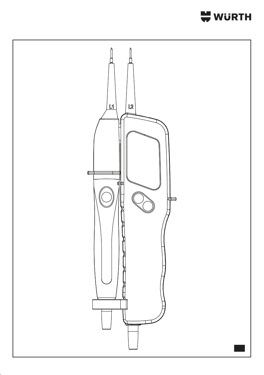
Einhandprüfung
Durch den an der Messleitung bendlichen Abstand-
halter, ist eine Arretierung der beiden Handteile
möglich.
Durch einfaches Drehen ist der Abstand der Mess-
spitzen einstellbar. ( Schuko/CEE)
Messstellenbeleuchtung
Durch längeres Betätigen der „L.H.“-Taste (Daten-
speicher) wird die Messstellenbeleuchtung ein- bzw.
ausgeschaltet.

7
Durchgangsprüfung
Legen Sie die Prüfspitzen an die zu prüfende
Leitung, Sicherung o.ä. an. Bei einem Widerstand
von 0 - 2 kΩ erscheint der Widerstandswert auf
dem Display und ein akustisches Signal ertönt bis
ca. 50 Ω. Ist der Messwert >2 kΩ, so erscheint im
Display die Überlaufanzeige „OL“.
FI/RCD-Auslösetest
Der Multi-Tester Pro LCD besitzt eine Last, die es
ermöglicht, einen FI/RCD-Schutzschalter mittels
zweier Taster (FI\RCD) auszulösen. Geprüft wird der
FI/RCD (max. 30 mA) zwischen Phase und Schutz-
leiter (max. 240 V).
Hintergrundbeleuchtung
Die Displayhintergrundbeleuchtung ist dauerhaft
gegeben
Frequenzmessung
Während der Spannungsmessung wird ebenfalls die
Frequenz der anliegenden Wechselspannung erfasst
und im Display mit den kleineren Ziern angezeigt.
Batteriewechsel
Sollte die Batterien sich entleert haben, erscheint
ein Warnsignal und das Gerät schaltet sich aus.
Wechseln Sie bitte die Batterien umgehend um die
Genauigkeit der Messwerte zu gewährleisten.
Zum Wechsel der Batterien ist das Batteriefach am
Hauptgehäuse zu önen.
Lösen Sie dazu die Schrauben mittels eines Schrau-
bendrehers. Achten Sie beim Einsatz der neuen
Batterien auf die richtige Polarität.
Verschliessen und verschrauben Sie das Batteriefach
wieder.
Wartung / Pege
■Das Gerät immer trocken und sauber halten.
Das Gerät darf mit einem feuchten Tuch gerei-
nigt werden.
Umwelthinweise
Werfen Sie das Gerät keinesfalls in
den normalen Hausmüll. Entsorgen
Sie das Gerät über einen zugelasse-
nen Entsorgungsbetrieb oder über
Ihre kommunale Entsorgungseinrich-
tung. Beachten Sie die aktuell
geltenden Vorschriften. Setzen Sie
sich im Zweifelsfall mit Ihrer Entsorgungseinrichtung
in Verbindung. Führen Sie alle Verpackungsmateria-
lien einer umweltgerechten Entsorgung zu.
Akkus/Batterien:
Werfen Sie Akkus/Batterien nicht in den Hausmüll,
ins Feuer oder ins Wasser. Akkus/Batterien sollen
gesammelt, recycelt oder auf umweltfreundliche
Weise entsorgt werden.
Gewährleistung
Für dieses Würth Gerät bieten wir eine Gewährleis-
tung gemäß den gesetzlichen/länderspezischen
Bestimmungen ab Kaufdatum (Nachweis durch
Rechnung oder Lieferschein).
Entstandene Schäden werden durch Ersatzlieferung
oder Reparatur beseitigt. Schäden, die auf unsach-
gemäße Behandlung zurückzuführen sind, sind von
der Gewährleistung ausgeschlossen.
Beanstandungen können nur anerkannt werden,
wenn das Gerät unzerlegt einer Würth Niederlas-
sung, Ihrem Würth Außendienstmitarbeiter oder
einer Würth autorisierten Kundendienststelle überge-
ben wird.
Technische Änderungen vorbehalten.
Für Druckfehler übernehmen wir keine Haftung.

8
Ersatzteile
Sollte das Gerät trotz sorgfältiger Herstell- und
Prüfverfahren einmal ausfallen, ist die Reparatur von
einem Würth masterService®ausführen zu lassen. In
Deutschland erreichen Sie den
Würth masterService® kostenlos unter Tel.
0800-WMASTER (0800-9 62 78 37).
In Österreich unter der Tel. 0800-20 30 13.
Bei allen Rückfragen und Ersatzteilbestellungen bitte
unbedingt die Artikelnummer laut Typenschild des
Gerätes angeben.
Konformitätserklärung
Das Produkt erfüllt die aktuellsten Richtlinien. Nähere
Informationen erhalten Sie auf www.wuerth.com.
Wir erklären in alleiniger Verantwortung, dass
dieses Produkt mit den folgenden Normen oder
normativen Dokumenten übereinstimmt:
Normen
• IEC/EN 61243-3
• DIN VDE 0682-401
gemäß den Bestimmungen der Richtlinien:
EG-Richtlinie
• 2004/108/EG
• 2006/95/EG
Technische Unterlagen bei:
Adolf Würth GmbH & Co. KG, Abt. PFW
General Manager General Manager
Adolf Würth
GmbH & Co. KG
Künzelsau: 19.02.2014

9
Note
Modication of the appliance or
manufacturing of attachments is not
permitted. Such modications can
result in personal injury or malfunc-
tions.
■Repairs to the device may only be carried out
by appointed and trained personnel. For such
purposes, always use original spare parts
from Adolf Würth GmbH & Co. KG. This is
to ensure and maintain safe operation of the
device.
The proper function of the
voltage tester must be
checked shortly before use.
Ensure that measuring lines
and device are in proper
working order.
■Check the device by connecting it to a known
power source, e.g. a 230 V socket.
■If the display for one or more functions fails
in the process, the device must no longer
be used and must be checked by qualied
specialist personnel.
■Electric shock may result in serious injuries or
death and may endanger the functionality of
objects (e.g. damage to the device).
■Read and comply with the ve safety rules:
1. Disconnect mains
2. Prevent reconnection
3. Test absence of voltage by approved
means (establish absence of voltage using
two-pole voltage indicators)
4. Ground and short-circuit
5. Protect adjacent live parts using covers
■Never direct the LED light, directly or indirectly
from reecting surfaces, towards the eye.
■Avoid operating the device in the vicinity of
electric welding machines, induction heaters
and other electromagnetic elds.
■After abrupt changes in temperature, the
device must be allowed to adapt to the new
ambient temperature and stabilise for approx.
30 minutes.
■Do not expose the device to high temperatures
for any length of time.
■Avoid dusty and humid ambient conditions.
■Measurement devices and accessories are not
toys and should always be kept away from
children!
■In commercial facilities the accident preven-
tion regulations (in Germany issued by the
commercial trade association for the safety
of electrical systems and equipment) must be
observed.
■Hold the device only at the handles, avoid
touching the test probes!
■Always test absence of voltage at only two
terminals!
For your safety
GB
Please read and comply with these
instructions prior to the initial
operation of your appliance.
Keep these operating instructions for
later use or for a subsequent owner.
WARNING - Prior to rst use
always read the Safety instruc-
tions!
Non-observation of the operating instructions and
the safety instructions could result in damage to
the device or danger for the operator and other
persons.
In case of transport damage, inform your vendor
immediately.
Safety Instructions

10
Intended Use
DC voltage tests from 4 V to 1400 V, AC voltage
tests from 3 V to 1000 V, polarity, phase sequence
and continuity tests up to 50 Ω plus FI/RCD tests
and resistance measurements tests up to 1999 Ω
can be carried out. Thanks to the rotating spacer,
single-handed operation is possible during voltage
measurement.
Thanks to its high protection class (IP65), Multi-Tester
Pro LCD can be used even under tough operating
conditions.
Any other use is considered an improper use.
The user is liable for damage resulting
from improper use.
Technical data
Item 0715 53 175
Display Backlit LCD
Nominal voltage
range 3 ... 1000 V AC (VRMS)
+ -3 digits
4 ... 1400 V DC + -3 digits
Input impedance 285 kΩ
Frequency display 0 ... 1000 Hz
Rotary eld display Yes
Switchable load 30 mA at 230 V
Cyclic duration
factor 30 s on / 240 s o
Continuity test 0 ... 50 Ω
Resistance measure-
ment 1...1999 Ω +- 5%
Protection category IP 65
Surge voltage
category CAT IV 1000 V
Test standard IEC/EN 61243-3
Power supply 2 x 1.5 V type AAA Micro
Item 0827 111
■Do not use with the battery compartment
open!
The measuring lines must be disconnected
from the measuring circuit during battery
replacement.
■A correct display is ensured within the temper-
ature range of -10°C to 55°C.
■The additionally displayed warning symbol
and acoustic signal at voltages > 35 V are
intended only as a warning of potentially fatal
voltages, not for measurement.
■Check the warning signal for audibility in loud
working environments before starting tests.
■Replace the batteries immediately if a contin-
uous warning signal sounds when switching
on.
■In order to protect the device from being dam-
aged, remove the batteries if the device is not
in use for a prolonged period of time.
■Use only genuine Würth accessories
and spare parts.
Safety Instructions

11
Operation
General
Voltages have priority. If there is no voltage at the
test probes (< 3 V), the device is in continuity/resist-
ance test mode.
Operation
To switch the device on, hold both measuring probes
together. After a short time the device switches o
automatically due to the "Auto Power O" function.
The remaining running time is displayed.
The screwing on or o of the measuring probe
adapter makes measuring at wall outlets more
convenient.
Self-test
Touch the test probes together for this test. The test
buzzer must sound clearly and the display must
indicate approximately “000”. If the LCD does
not light up or lights up only weakly, the batteries
must be replaced. If the device does not function
even with new batteries, it must be protected from
improper use.
DC voltage check
Upon placing of the probe tips on a DC voltage
within the rated voltage range, the voltage is
displayed in volts and “DC” is additionally output
on the display. If a negative voltage is present at
probe tip “L1”, then a “-” is displayed in front of the
value. For voltages greater than approximately 35
V, the potentially fatal voltage is indicated by the
LED ashing behind the display and an audible and
vibrating signal.
The voltage value is displayed even in
the batteries are discharged.
AC voltage (VRMS) check
Upon placing of the probe tips on an AC voltage
within the rated voltage range, the voltage is
displayed in volts and “AC” is additionally output
on the display. The mains frequency is likewise
displayed. For voltages greater than approximately
35 V, the potentially fatal voltage is indicated by
the LED ashing behind the display and an audible
signal.
The voltage value is displayed even in
the batteries are discharged.
DATA HOLD function
Brief pressing of the “L.H.” key (data hold) saves the
measured value currently displayed on the LCD. The
“DATA HOLD” function is indicated by the symbol
“D.H.” on the display eld and can be switched o
again through a further pressing of the same key.
Phase check
Touch a conductor with test probe "L1".
On contact with a phase of at least 100 V~, the
indication "<L" is output to the LCD.
For determination of the phase conductor, the per-
ceptibility of the display may be impaired, e.g. by
insulating devices for protection against accidental
direct contact, in unfavourable positions, for exam-
ple on wooden ladders or insulating oor coverings,
a non-earthed voltage or under unfavourable light
conditions.
Rotary field check (max. 400 V)
Grip all round handles L 1 and L2.
Hold test probes L 1 and L2 against two outer
conductors (phases) and check whether the outer
conductor voltage of e.g. 400 V is measured.
A clockwise rotating eld (phase L1 before phase
L2) is indicated if the letter "R” is output to the
display.
An anti-clockwise rotating eld (phase L2 before
phase L1) is indicated if the letter “L” is output to the
display.
The rotary eld check must always be repeated with
reversed test probes. The direction of rotation must
thereby change.
The rotary eld check can be
performed above 200 V, 50/60 Hz
(phase against phase) in the earthed
3-phase AC grid.
Single-handed check
Thanks to the spacer located on the measuring line,
locking of the two hand parts is possible.
The distance between the test probes can be
adjusted simply by turning. (Schuko/CEE plug)

12
Measuring point light
Holding the “L.H” (data hold) button depressed for
a short time switches the measuring point light on
and o.
Continuity test
Place the test probes against the lead, fuse, etc. to
be tested. At a resistance of 0 - 2 kΩ, the resistance
value is output to the display and an audible signal
sounds to approximately 50 Ω. If the measured
value >2 kΩ, the overow indicator “OL” is output
to the display.
FI/RCD trip test
The Multi-Tester Pro LCD has a load which allows
an FI/RCD circuit breaker to be tripped by means
of two buttons (FI\RCD). The FI/RCD (max. 30 mA)
is tested between phase and PE conductor (max.
240 V).
Backlighting
Backlighting is permanently activated.
Frequency measurement
During voltage measurement, the frequency of the
applied AC voltage is measured and output to the
display in small characters.
Battery changing
If the batteries have become discharged, a warning
signal is displayed and the device switches o.
Replace the batteries immediately in order to ensure
the accuracy of the measured values.
To change the batteries, open the battery compart-
ment on the main housing.
Loosen the screws using a suitable screwdriver. Pay
attention that the new batteries are inserted with the
correct polarity!
Close the battery compartment again and tighten
the screws.
Maintenance / care
■Keep the device always dry and clean. The
device may be cleaned using a damp cloth.
Environmental Instructions
Do not throw the device away with
normal household waste. Dispose of
the device via an approved waste
disposal company or via your local
authority waste disposal facility.
Observe the currently valid regula-
tions. In case of doubt, contact your
waste disposal facility. Dispose of all packaging in
an environmentally sound manner.
Batteries:
Do not dispose of batteries with domestic waste,
do not expose to re or water. Collect and recy-
cle batteries or dispose of with due care for the
environment.
Warranty
We provide a warranty for this Würth device from
the date of purchase and in accordance with the
legal/country-specic regulations (proof of purchase
through invoice or delivery note).
Any damage arising is remedied by the supply
of spare parts or by repair. Damage caused by
improper handling is not covered by the warranty.
Claims under warranty can only be accepted if
the device is returned fully assembled to a Würth
agency, your Würth sales representative or an
authorised Würth customer service workshop.
We reserve the right to make technical changes.
We accept no liability for printing errors.

13
Spare parts
If, despite careful manufacturing and testing pro-
cesses, the device should become faulty, have
the repair carried out by a Würth masterService®
station.
Always quote the article number as given on the
name plate, with any enquiries or spare parts
orders.
Declaration of Conformity
The product conforms to the present directives. For
more detailed information, go to www.wuerth.com.
We herewith declare that this product conforms to
the following standards and directives:
Standards
• IEC/EN 61243-3
• DIN VDE 0682-401
in accordance with the regulations stipulated in the
directives:
EC Directive
• 2004/108/EC
• 2006/95/EC
Technical documentation at:
Adolf Würth GmbH & Co. KG, Abt. PFW
General Manager General Manager
Adolf Würth
GmbH & Co. KG
Künzelsau: 19.02.2014

14
Nota
È vietato apportare modiche all'ap-
parecchio o realizzare dispositivi
aggiuntivi. Tali modiche possono
portare a danni alle persone e ad
anomalie di funzionamento.
■I lavori di riparazione sull'apparecchio pos-
sono essere eseguiti solo da personale inca-
ricato e con adeguata formazione. Per questi
lavori utilizzare sempre i pezzi di ricambio
originali della Adolf Würth GmbH & Co.
KG. In questo modo è garantita la sicurezza
dell'apparecchio.
Prima di mettere in funzione il
tester, controllarne il funzio-
namento. Accertarsi che i
puntali e il dispositivo siano in
perfette condizioni.
■Controllare il dispositivo su una fonte di ten-
sione nota (p. es. es. una presa da 230 V.
■Se durante questo controllo manca la visualiz-
zazione di una o più funzioni, il dispositivo non
deve essere più usato e deve essere control-
lato da personale specializzato.
■La scossa elettrica può comportare il decesso
o lesioni gravi per le persone e rischi per la
funzionalità degli oggetti (p. es. può danneg-
giare il dispositivo.
■Si prega di rispettare le cinque regole per la
sicurezza:
1. Distacco della tensione
2. Protezione contro la riaccensione
3. Controllo dell'assenza di tensione (da con-
trollare sui 2 poli)
4. Collegamento a massa e cortocircuito
5. Coprire i pezzi vicini posti sotto tensione
■Non rivolgere mai la luce a LED direttamente
verso gli occhi o indirettamente attraverso
superci riettenti.
■Non mettere in funzione l'apparecchio nei
pressi di saldatrici elettriche, riscaldamenti ad
induzione o di altri campi elettromagnetici.
■Dopo un brusco cambio di temperatura,
l'apparecchio, prima dell'uso per la stabilizza-
zione, deve adattarsi per circa 30 minuti alla
nuova temperatura ambiente.
■Non esporre l'apparecchio ad elevate tempe-
rature per un periodo prolungato.
■Evitare condizioni ambientali con polveri e
umidità.
■Gli strumenti di misura e gli accessori non sono
giocattoli e non devono essere alla portata dei
bambini.
■Negli allestimenti industriali, rispettare le
prescrizioni antinfortunistiche dell'associazione
professionale degli industriali per gli impianti e
i mezzi di esercizio elettrici.
■Tenere l'apparecchio solo per le impugnature
ed evitare di toccare i puntali di prova.
■Controllare l'assenza di tensione sempre e solo
sui due poli.
Informazioni per la sicurezza
IT
Prima di utilizzare l'apparecchio per
la prima volta, leggere e seguire
queste istruzioni per l'uso.
Conservare le presenti istruzioni per
l'uso per consultarle in un secondo
tempo o per consegnarle a successivi
proprietari.
AVVERTENZA - Prima di mettere in
funzione l'apparecchio per la prima
volta leggere attentamente le
Avvertenze di sicurezza.
La mancata osservanza delle istruzioni d'uso
e delle norme di sicurezza può causare danni
all'apparecchio e presentare pericoli per l'utente e
le altre persone.
Eventuali danni di trasporto vanno comunicati
immediatamente al proprio rivenditore.
Avvertenze di sicurezza

15
Uso conforme
È
possibile eseguire controlli di tensioni continue
da 4 V a 1400 V e di tensioni alternate da 3 V a
1000 V, polarità, direzione del campo di rotazione
e controlli di continuità no a 50
Ω
nonché test di
interruttori dierenziali/salvavita (RCD) e misurazioni
della resistenza no a 1999 Ω. Grazie al distan-
ziale girevole è possibile eseguire misurazioni della
tensione con una mano sola.
Il Multi-Tester Pro LCD è utilizzabile anche per impie-
ghi gravosi grazie all'elevato grado di protezione
(IP65).
Qualunque utilizzo diverso da quelli indicati si consi-
dera utilizzo non conforme.
La responsabilità per i danni dovuti ad un
utilizzo non conforme alle norme è esclusi-
vamente dell'utente.
Dati tecnici apparecchio
Art. 0715 53 175
Display Display LCD retroilluminato
tensione portata 3 ... 1000 V AC (TRMS)
+ -3 digit
4 ... 1400 V DC + -3 digit
impedenza
d'ingresso 285 kΩ
frequenza 0 ... 1000 Hz
indicazione Sì
carico d'interruzione 30 mA a 230 V
ciclo di funziona-
mento 30 s acceso/240 s spento
test di continuità 0 ... 50 Ω
resistenza 1...1999 Ω +- 5%
grado di protezione IP 65
protezione
sovratensione CAT IV 1000 V
norme IEC/EN 61243-3
alimentazione 2 x 1,5 V tipo AAA ministilo
Art. 0827 111
■Non utilizzare con il vano batterie aperto.
I puntali devono essere allontanati dal circuito
di misurazione durante la sostituzione della
batteria.
■La perfetta visualizzazione è assicurata nell'in-
tervallo di temperature comprese fra -10 °C e
+ 55 °C.
■La visualizzazione supplementare del
simbolo di avvertimento e il segnale acustico
con tensioni sopra i 35 V non fungono da
misurazione, ma solo da avvertimento per la
presenza di tensioni con pericolo di morte.
■Vericare che il segnale acustico di avverti-
mento sia udibile prima di eseguire misurazioni
nel volume presente nell'ambiente in questione.
■Sostituire subito le batterie quando, all'ac-
censione, si avverte un segnale continuo di
avvertimento.
■Rimuovere le batterie per proteggere l'ap-
parecchio dai danni, in caso di prolungato
inutilizzo dello stesso.
■Utilizzare solo accessori e pezzi di
ricambio originali Würth.
Avvertenze di sicurezza

16
Uso
Generalità
Le tensioni hanno la priorità. In assenza di tensione
sui puntali di prova (< 3 V), l'apparecchio si trova in
modalità di transito/resistenza.
Funzione
Per accendere l'apparecchio tenere le punte di misu-
razione una contro l'altra. Poco dopo, l'apparecchio
si spegne automaticamente con la funzione "Auto
Power O". Il tempo restante viene visualizzato.
La misurazione delle prese elettriche è comoda gra-
zie alla possibilità di avvitare o svitare gli adattatori
delle punte di misurazione.
Test di autodiagnostica
Per il test tenere i puntali di prova uno contro l'altro.
Il cicalino di controllo deve emettere un suono
chiaro e l'indicatore deve mostrare il valore "000".
Se il display LCD è spento o se la luce è debole, è
necessario cambiare le batterie. Se l'apparecchio
non funziona con le batterie nuove, è necessario
evitare che venga utilizzato erroneamente.
Misurazione della tensione continua
Mettendo i puntali di prova su una tensione continua
all'interno dell'intervallo di tensione nominale viene
visualizzata la tensione in volt e sul display compare
inoltre la scritta "DC". Se sul puntale di prova "L1" è
presente una tensione negativa, viene visualizzato
un "-" (meno) davanti al valore. A partire da una
tensione di circa 35 V la tensione che costituisce
un pericolo di morte viene indicata dal lampeggio
del LED dietro il display e viene emesso un segnale
acustico con vibrazione.
Il valore di tensione viene indicato
anche con le batterie scariche.
Misurazione della tensione alternata
(TRMS)
Mettendo i puntali di prova su una tensione alter-
nata all'interno dell'intervallo di tensione nominale,
viene visualizzata la tensione in volt e sul display
compare inoltre la scritta "AC". Inoltre viene visualiz-
zata la frequenza di rete. A partire da una tensione
di circa 35 V la tensione che costituisce un pericolo
di morte viene indicata dal lampeggio del LED die-
tro il display e viene emesso un segnale acustico.
Il valore di tensione viene indicato
anche con le batterie scariche
Funzione DATA HOLD
Premendo brevemente il tasto "L.H." (memoria dati)
è possibile salvare il valore misurato sul display LCD.
La funzione "DATA HOLD" è indicata sul campo del
display dal simbolo "D.H." e può essere disattivata
premendo di nuovo brevemente lo stesso tasto.
Misurazione della fase
Toccare un conduttore con il puntale di prova "L1".
In presenza di una fase di min. 100 V~ compare la
scritta "<L" sul display LCD.
Per stabilire i conduttori di fase è possibile che la
visibilità dell'indicatore risulti alterata, ad esempio a
causa di dispositivi di isolamento per la protezione
dal contatto diretto, in posizioni sfavorevoli, come
su scale in legno o su pavimenti isolanti, in presenza
di una tensione senza messa a terra o in caso di
condizioni di illuminazione sfavorevoli.
Misurazione del campo di rotazione
(max. 400 V)
Tenere le impugnature L1 e L2 aerrando l'intera
supercie.
Appoggiare i puntali di prova L1 e L2 su due
conduttori esterni (fasi) e vericare la presenza di
tensione sui conduttori esterni, ad esempio a 400 V.
Un campo di rotazione destrorso (fase L1 prima
della fase L2) è presente se sul display compare la
lettera "R".
Un campo di rotazione sinistrorso (fase L2 prima
della fase L1) è presente se sul display compare la
lettera "L".
Alla determinazione del campo di rotazione deve
seguire sempre un controllo con puntali di prova
invertiti. In questo caso, il senso di rotazione deve
cambiare.
Il controllo del campo di rotazione è
possibile a partire da 200 V, 50/60
Hz (fase contro fase) in una rete a
corrente trifase con messa a terra.
Misurazione con una mano sola
I distanziali presenti sul puntale permettono di bloc-
care le due impugnature.
Con una semplice rotazione è possibile regolare la
distanza dei puntali. (Schuko/CEE)

17
Illuminazione del punto di misura
Tenendo premuto il tasto "L.H." (memoria dati) si
attiva o disattiva l'illuminazione del punto di misura.
Prova di continuità
Appoggiare i puntali di prova sul cavo, sul fusibile o
sul componente che si desidera controllare. Con una
resistenza di 0 - 2 kΩ viene visualizzato il valore
di resistenza sul display e viene emesso un segnale
acustico no a circa 50 Ω. Se il valore misurato è
>2 kΩ, sul display compare l'indicazione di over-
ow "OL".
Test di intervento per interruttore
differenziale/salvavita (RCD)
Il Multi-Tester Pro LCD è dotato di un carico che con-
sente di far intervenire un interruttore dierenziale/
salvavita (RCD) per mezzo di due pulsanti (FI\RCD).
L'interruttore dierenziale/salvavita (RCD) (max.
30 mA) viene controllato fra fase e conduttore di
protezione (max. 240 V).
Illuminazione di fondo
L'illuminazione del display è continua
Misurazione della frequenza
Durante la misurazione della tensione viene rilevata
e indicata con piccole cifre sul display anche la
frequenza della tensione alternata applicata.
Sostituzione delle batterie
Se le batterie si scaricano, viene visualizzato un
segnale di avvertimento e l'apparecchio si spegne.
Sostituire immediatamente le batterie per garantire
la precisione dei valori misurati.
Per cambiare le batterie, aprire il vano batterie sul
corpo principale.
A tal ne, svitare le viti con un cacciavite. Quando
si inseriscono le batterie nuove fare attenzione alla
giusta polarità.
Richiudere il vano batterie e ssarlo con le viti.
Manutenzione/cura
■Mantenere sempre asciutto e pulito l'interno
dell'apparecchio. L'apparecchio può essere
pulito con un panno umido.
Note per la tutela dell'ambiente
Non gettare in nessun caso l'appa-
recchio nei riuti domestici. Lo
smaltimento dell'apparecchio deve
essere adato a un'azienda di
smaltimento autorizzata oppure agli
enti pubblici preposti. Rispettare le
disposizioni di legge attualmente in
vigore. In caso di dubbi contattare l'ente pubblico
addetto allo smaltimento. Smaltire i materiali
d’imballaggio in base alle normative in materia di
tutela dell'ambiente.
Accumulatori/batterie:
Non gettare accumulatori/batterie tra i riuti
domestici, nel fuoco o nell'acqua. Gli accumulatori/
le batterie devono essere raccolti, riciclati o smaltiti
correttamente nel rispetto dell'ambiente.
Garanzia
Per il presente apparecchio Würth il costruttore
fornisce una garanzia secondo le disposizioni
di legge o speciche del paese dal momento
dell'acquisto (da dimostrare con fattura o bolla
d'accompagnamento).
In caso di danni, l'apparecchio verrà sostituito o
riparato. I danni riconducibili ad un uso improprio
dell'apparecchio sono esclusi dalla garanzia.
Le richieste potranno essere riconosciute soltanto
se l'apparecchio verrà consegnato integro ad una
liale Würth, ad un rappresentante Würth o al servi-
zio di assistenza clienti autorizzato da Würth.
Con riserva di modiche tecniche.
Il costruttore non si assume alcuna responsabilità
per eventuali refusi.

18
Pezzi di ricambio
Se l’apparecchio, nonostante l’accuratezza adottata
nel processo di produzione e controllo, non dovesse
funzionare, fare eseguire la riparazione necessaria
da Würth masterService®.
Per qualsiasi domanda od ordinazione di ricambi,
indicare sempre la matricola dell'articolo indicata
sulla targhetta identicativa dell'apparecchio.
Dichiarazione di conformità
Il prodotto è conforme alle direttive più recenti.
Maggiori informazioni sono disponibili all'indirizzo
www.wuerth.com.
Dichiariamo sotto la nostra responsabilità che
questo prodotto è conforme alle seguenti norme o
documenti normativi:
Norme
• IEC/EN 61243-3
• DIN VDE 0682-401
secondo le disposizioni delle direttive:
Direttiva CE
• 2004/108/CE
• 2006/95/CE
Documentazione tecnica presso:
Adolf Würth GmbH & Co. KG, rep. PFW
General Manager General Manager
Adolf Würth
GmbH & Co. KG
Künzelsau: 19/02/2014

19
Remarque
Il est interdit de procéder à des modi-
cations sur l’appareil ou de fabriquer
des appareils complémentaires. De
telles modications risquent de provo-
quer des dommages corporels et des
dysfonctionnements.
■Les réparations sur l’appareil ne doivent être
eectuées que par des personnes mandatées
et formées. Pour ceci, il faut toujours utiliser les
pièces détachées de la société Adolf Würth
GmbH & Co. KG. Il est ainsi garanti que la
sécurité de l’appareil demeure préservée.
Le fonctionnement du détec-
teur de tension doit ętre
contrôlé peut avant la mise en
œuvre. Assurez-vous que les
ls de test et l’appareil soient
dans un état impeccable.
■Contrôlez l’appareil sur une source de tension
connue, par ex. une prise de 230 V.
■Si l’achage d’une ou plusieurs fonctions
tombe alors en panne, l’appareil ne doit plus
être utilisé et il doit faire l’objet d’un contrôle
par le personnel technique.
■Un choc électrique peut entraîner la mort de
personnes ou de graves dommages corporels
et représenter un risque pour le fonctionnement
d’objets (p.ex. l’endommagement de l’appa-
reil).
■Veuillez respecter les cinq règles de sécurité :
1. Déconnecter
2. Protéger contre la remise en marche
3. Constater l’absence de tension (l’absence
de tension doit être constatée sur 2 pôles)
4. Mettre à la terre et court-circuiter
5. Couvrir les pièces avoisinantes se trouvant
sous tension
■Ne dirigez jamais la lumière LED directement
ou indirectement par des surfaces rééchis-
santes vers l’œil.
■Evitez un fonctionnement de l’appareil à
proximité d’appareils de soudure électriques,
de dispositifs de chauage par induction et
d’autres champs électromagnétiques.
■Après des changements abrupts de tempéra-
ture, l’appareil doit être adapté à la nouvelle
température ambiante pendant environ 30
minutes avant l’utilisation en vue de la stabili-
sation.
■N’exposez pas l’appareil durant des périodes
prolongées à des températures élevées.
■Evitez les conditions ambiantes poussiéreuses
et humides.
■Les appareils de surveillance et les accessoires
ne sont pas des jouets, ils ne doivent pas être
mis dans les mains d’enfants !
■Dans les établissements artisanaux et indus-
triels, les directives de prévention des accidents
de l’association des caisses professionnelles
d’assurance accidents de l’industrie et de l’arti-
sanat applicables aux installations et équipe-
ments électriques doivent être respectées.
■Saisissez l’appareil uniquement par les
poignées, évitez de toucher les pointes de
contrôle !
Pour votre sécurité
FR
Lisez attentivement ce mode d’emploi
avant la première utilisation de
l’appareil et agissez en consé-
quence.
Conservez ce mode d’emploi pour
un usage ultérieur ou pour les futurs
propriétaires.
AVERTISSEMENT - Avant la
première mise en service, lire
impérativement les consignes de
sécurité !
En cas de non-respect du mode d’emploi et des
consignes de sécurité, des dommages sur l’ap-
pareil et des dangers pour l’opérateur et d’autres
personnes peuvent se produire.
En cas de dommages dus au transport, informer
immédiatement le revendeur.
Consignes de sécurité

20
Utilisation conforme
Il est possible de réaliser des tensions continues
de 4 V à 1400 V et des tensions alternatives de
3 V à 1000 V, des contrôles de polarité, d’ordre
de phases et de continuité jusqu’à 50 Ωainsi que
des tests FI/RCD et des mesures de résistance
jusqu’à 1999 Ω. Grâce à l’écarteur pivotant, une
commande d’une seule main est possible pour les
mesures de tension.
Le multi-testeur pro-LCD est également utilisable dans
des conditions rudes grâce à l’indice de protection
élevé (IP65).
Toute utilisation dépassant ce cadre est comprise
comme non conforme.
L’utilisateur est responsable des dom-
mages survenus en cas d’utilisation non
conforme.
Paramètres de l’appareil
Réf. 0715 53 175
Achage Eclairage de fond actif de
l’écran LC
Gamme de tensions
nominales 3 ... 1000 V CA (TRMS)
+ -3 chires
4 ... 1400 V CC
+ -3 chires
Impédance d’entrée 285 kΩ
Achage de fré-
quence 0 ... 1000 Hz
Achage du champ
magnétique rotatif Oui
Charge commutable 30 mA à 230 V
Durée d’activation 30 s actif /240 s inactif
Contrôle de conti-
nuité 0 ... 50 Ω
Mesure de résis-
tance 1...1999 Ω +- 5%
Indice de protection IP 65
Catégorie de surten-
sion CAT IV 1000 V
Norme de contrôle CEI/EN 61243-3
Alimentation élec-
trique 2 x 1,5 V type AAA Micro
Réf. 0827 111
■Eectuez toujours les contrôles de neutralité
électrique sur deux pôles !
■Ne pas utiliser avec compartiment à piles
ouvert !
Pendant un remplacement des piles, les ls de
test doivent être ôtés du circuit de mesure.
■Un achage impeccable est garanti dans la
gamme de températures de -10 °C à + 55 °C.
■Le symbole d’avertissement s’achant en plus
et le signal acoustique en cas de tensions >
35 V servent uniquement à mettre en garde
contre les tensions mortelles, et non pour la
mesure.
■Contrôler l’audibilité de la tonalité avec le bruit
ambiant avant les contrôles.
■Remplacer immédiatement les piles lorsqu’un
signal d’alerte permanent retentit à la mise en
circuit.
■An de protéger l’appareil contre tout
endommagement, retirez les piles en cas de
non-utilisation prolongée de l’appareil.
■Utilisez uniquement des accessoires
et pièces de rechange d’origine de
Würth.
Consignes de sécurité
Other manuals for PRO II LCD
1
This manual suits for next models
1
Table of contents
Languages:
Other Würth Test Equipment manuals

Würth
Würth 0715 53 090 User manual

Würth
Würth 0715 53 001 Quick guide

Würth
Würth Video-scope PRO User manual

Würth
Würth 0715 53 220 Quick guide

Würth
Würth 0715 53 07 Quick guide

Würth
Würth 0715 53 200 User manual

Würth
Würth 0704 510 Quick guide

Würth
Würth 0715 53 200 Quick guide

Würth
Würth PRO II LCD Quick guide

Würth
Würth 1952 006 920 Quick guide