East Tester ET1300 User manual

Product Basic Function
ET13 series DC programmable electronic load provides 1mV/10mV, 1mA/10mA high resolution and
precision with superior performance. It is equipped with 12 common modes and complete test functions,
which can be widely used in charger, switching power supply, linear power supply, battery and other
production line testing.
Key Features:
User-friendly Design:
It adopts 3.5-inch TFT LCD screen with rich display contents;
The operation process is simple and convenient, and with visual interface display system, it is
easy to get started.
Key lock function to prevent misoperation;
High-performance load:
It provides CC, CV, CR, CP and CC+CV, CR+CV several basic measurement modes;
It provides professional battery test;
It provides professional LED test;
The Tran test mode can test the dynamic output performance of the power supply;
The scan test mode can test the continuity of power output within a certain range;
Support 4-wire measurement;
The list test mode can simulate a variety of loading status changes;
The short circuit test can be used to simulate load short circuit;
Support external trigger input;
Built-in buzzer alarm;
Maintain data storage in case of power failure;
Remote operation via USB, RS-232or 485 (optional) interfaces;
Multiple safety protection:
It provides overcurrent, overvoltage, overpower, over temperature protection. The overvoltage
and overcurrent parameters can be set flexibly, so as to effectively protect the load;
It has intelligent fan speed control function, which can effectively reduce the fan noise when it is
working.
With input polarity reverse prompt;
General technical specifications:
Power supply voltage: 220Vac±10%, 110Vac±10%, 45-65Hz
Display: 3.5-inch TFT LCD screen with resolution of 480×320
Operating temperature: 0℃to 40℃
Storage temperature: -10℃to 70℃
Relative humidity: < 80%
Interface: standard USB, RS232 or 485(optional)
Size: 320mm×220mm×100mm (width × height × depth)
Standard accessories:
Three-core power cord 1
Power fuse 2
User manual 1

Content
1. Quick Start Guide...................................................................................................... 1
1.1 Front panel LCD display..........................................................................................1
1.2 Front panel key.........................................................................................................1
1.3 Key Description....................................................................................................... 2
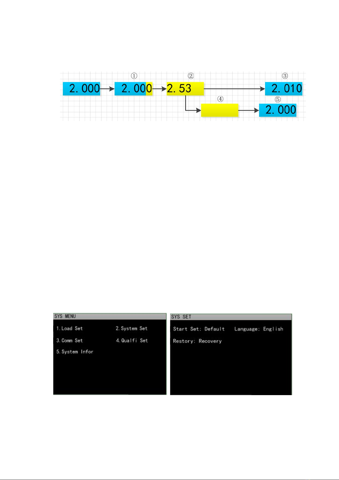
1.4 Numeric parameter settings......................................................................................2
2.Function operation................................................................................................... 3
2.1 Remote/local switching............................................................................................3
2.2 System Setup............................................................................................................3
2.3 Load Setup............................................................................................................... 4
2.4 Basic mode............................................................................................................... 4
2.4.1 Constant current mode.................................................................................. 4
2.4.2 Constant voltage mode..................................................................................5
2.4.3 Constant resistance mode..............................................................................5
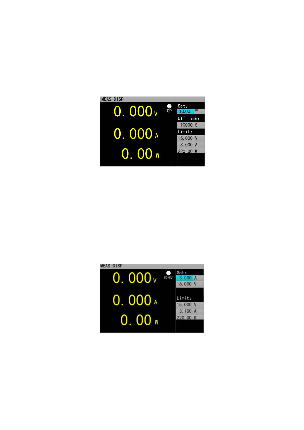
2.4.4 Constant power mode....................................................................................6
2.4.5 Constant current to constant voltage mode................................................... 6
2.4.6 Constant resistance to constant voltage mode...............................................6
2.5 Tran Test.................................................................................................................. 7
2.6 List Test....................................................................................................................8
2.7 Scan Test................................................................................................................ 11
2.8 Battery Test............................................................................................................ 12
2.9 LED Test................................................................................................................ 13
2.10 Short Circuit Test................................................................................................. 14
2.12 Protection function............................................................................................... 14
2.13 Trigger function................................................................................................... 14
2.14 Qualification test.................................................................................................. 14
2.15 Other system settings........................................................................................... 15
2.15.1 Key-Lock Function................................................................................... 15
2.16 Communication port and External expansion port...............................................15
2.16.1 Communication port..................................................................................15
2.16.2 Expansion port.......................................................................................... 16
2.16.3 Current monitoring terminal..................................................................... 16
Technical specifications............................................................................................... 17

ET1301/1302/1303/1304 Programmable DC Electronic Load User Manual
Hangzhou Zhongchuang Electronics Co., Ltd.
1
1. Quick Start Guide
1.1 Front panel LCD display
Icon bar: there are five types of icons on the electronic load interface
1.2 Front panel key
It indicates keyboard lockout
It indicates remote control
It indicates fan failure
Unreg
It indicates not satisfy the set value
Sense
It indicates 4-wire measurement
PASS
It indicates PASS

ET1301/1302/1303/1304 Programmable DC Electronic Load User Manual
Hangzhou Zhongchuang Electronics Co., Ltd.
2
1.3 Key Description
Key name
Function of the key
【On/Off】
Channel switch key, which is used to control the load channel status:
on/off.
【Mode】
Set the load mode.
【Utility】
For system general settings.
【Menu】
Parameter settings for non-basic mode.
【0】~【9】
Numeric key for entering numbers.
【.】
For entering the decimal point.
【ESC】
Back key or number deletion key.
【Enter】
Enter or select key. Long press for more than 3 seconds and the keyboard
will be locked. Under the locked state, some keys cannot be used.
【Local】
For switching to the local mode.
【Trigger】
Trigger key for manual trigger.
【 】、【 】
Keys used for moving the cursor left or right.
【Range-I】
Shortcut key for current range switching
【Range-V】
Shortcut key for voltage range switching
1.4 Numeric parameter settings
Numeric parameters can be set in two ways.
1. As shown in figure 1.4.1, ①Press【Enter】to enter the edit mode. ②In edit mode, press the
arrow keys【 】、【 】 to select the corresponding number of digits. ③Turn the knob to adjust the
value. ④Press【Enter】or【Esc】to exit the edit mode. Numeric parameter setting is then completed.
Figure 1.4.1.
2.As shown in figure 1.4.2, ①press【Enter】to enter the edit mode. ②Press the numeric key to
enter the value. ③Press 【Enter】to confirm and exit the edit mode. Parameter setting is then completed.

ET1301/1302/1303/1304 Programmable DC Electronic Load User Manual
Hangzhou Zhongchuang Electronics Co., Ltd.
3
When entering the value in step②:④press 【Esc】to delete the previous number until all the numbers
are deleted. ⑤When all the numbers are deleted, press 【Esc】again to exit the edit mode and end the
parameter setting.
Figure 1.4.2
2.Function operation
To ensure stable and safe operation of the load and the source to be measured, make sure that the load
and the source to be tested are connected in a red-positive and black-negative manner before using the
load to test the source to be measured. After that, first turn on the power output, and then turn on the load.
2.1 Remote/local switching
When the load is in remote operation mode, the corresponding icon will be displayed on the top of
the interface. At this time, the interface is locked, and the status and operation of the instrument can be
controlled through the commands of the upper computer, or switch back to the local operation mode by
pressing【Local】on the panel.
2.2 System Setup
Press【Utility】to enter the system menu interface, as shown in figure. 2.2.1. Rotate the knob to select
and enter the corresponding sub-menu. The operations of language setting, restore factory setting and start
settings can be completed in the system setting interface, as shown in figure 2.2.2.
Operating instructions: 1. Select the operation option by rotating the knob. 2. Press [Enter] to enter
the sub-menu interface or switch the contents of the operation option. 3. Press【Esc】to return to the
previous interface.
Figure. 2.2.1 System menu interface Figure 2.2.2 System setting interface

ET1301/1302/1303/1304 Programmable DC Electronic Load User Manual
Hangzhou Zhongchuang Electronics Co., Ltd.
4
2.3 Load Setup
Load setup interface can be entered through the system menu, as shown in figure 2.3.The load range,
limit value, off-delay and other related settings can be completed in this interface.
Operating instructions: 1. Select the operation option by turning the knob. 2. Press【Enter】to switch
set options for non-numeric parameters. 3. As for the setting of numeric parameters, please refer to 1.4
Numeric Parameter Setting for details. 4. Press【Esc】to return to the previous interface.
Figure 2.3 Load setup interface
2.4 Basic mode
Electronic load can work in the following basic measurement modes: constant current mode (CC),
constant voltage mode (CV), constant resistance mode (CR), constant power mode (CP), constant current
to constant voltage mode (CC+CV), constant resistance to constant voltage mode (CC+CR). The
parameter settings for the above six modes can be done in the measurement interface. In addition, press
[Mode] on the main interface of any mode to enter the mode selection interface, as shown in figure 2.4.
Operating instructions: 1 Select the action item by turning the knob. 2. Press【Enter】to confirm the
selected mode. 3. Press【Esc】to return to the previous interface.
Figure 2.4 Mode selection interface
2.4.1 Constant current mode
In constant current mode, the electronic load consumes a constant current regardless of whether the
input voltage changes or not.
Operating instructions: 1 Select the operation option by turning the knob. 2. For parameter settings,
please refer to 1.4 Numeric Parameter Setting for details. 3. Press the corresponding【On/Off】to turn on
the load..

ET1301/1302/1303/1304 Programmable DC Electronic Load User Manual
Hangzhou Zhongchuang Electronics Co., Ltd.
5
Figure 2.4.1 Constant current mode
2.4.2 Constant voltage mode
In constant voltage mode, the electronic load will consume enough current to keep the input voltage
at the set voltage.
Operating instructions: 1 Select the action item by turning the knob. 2. For parameter settings, please
refer to 1.4 Numeric Parameter Setting for details. 3. Press the corresponding【On/Off】to turn on the
load..
Figure 2.4.2 Constant voltage mode
2.4.3 Constant resistance mode
In constant resistance mode, the load is equivalent to a constant resistance, and the load will consume
a current that varies with the input voltage.
Operating instructions: 1 Select the action item by turning the knob. 2. For parameter settings, please
refer to 1.4 Numeric Parameter Setting for details. 3. Press the corresponding【On/Off】to turn on the
load..
Figure 2.4.3 Constant resistance mode

ET1301/1302/1303/1304 Programmable DC Electronic Load User Manual
Hangzhou Zhongchuang Electronics Co., Ltd.
6
2.4.4 Constant power mode
In constant power mode, the load consumes a constant power. When the input voltage changes, the
load will adjust the current accordingly to keep the consumed power at the set power value.
Operating instructions: 1 Select the action item by turning the knob. 2. For parameter settings, please
refer to 1.4 numeric parameter settings. 3. Press the corresponding【On/Off】to turn on the load..
Figure 2.4.4 Constant power mode
2.4.5 Constant current to constant voltage mode
The constant current to constant voltage mode is to prevent the source to be measured from being
damaged by overcurrent discharge. In this mode, when the source to be measured cannot output the
current value set by the load, it will automatically switch from constant current mode to constant voltage
mode.
Operating instructions: 1 Select the action item by turning the knob. 2. For parameter settings, please
refer to 1.4 Numeric Parameter Setting for details. 3. Press the corresponding【On/Off】to turn on the
load.
Figure 2.4.5 Constant current to constant voltage mode
2.4.6 Constant resistance to constant voltage mode
The constant resistance to constant voltage mode is to prevent the source to be measured from being
damaged by overcurrent discharge. In this mode, when the source to be measured cannot output enough
current to maintain the set resistance, the load will switch from constant resistance mode to constant
voltage mode.

ET1301/1302/1303/1304 Programmable DC Electronic Load User Manual
Hangzhou Zhongchuang Electronics Co., Ltd.
7
Operating instructions: 1 Select the action item by turning the knob. 2. For parameter settings,
please refer to 1.4 Numeric Parameter Setting for details. 3. Press the corresponding【On/Off】to turn on
the load..
Figure 2.4.5 Constant resistance to constant voltage mode
2.5 Tran Test
Tran test can be switched back and forth between two currents or voltages set by the load. This
function can be used to test the dynamic characteristics of the power source. Moreover, the Tran test is
divided into three modes: continuous mode, pulse mode and trigger mode, as described below:
Continuous mode: in this mode, the load can continuously switch between level A and level B after
the test is started.
Pulse mode: in this mode, after the test is started, the load will switch from level A to level B every
time it receives a trigger signal, and then switch back to level A after maintaining level B pulse
width.
Trigger mode: in this mode, after the test is started, the load will switch between level A and level B
every time it receives a trigger signal. Setting the pulse width will not work in this mode.

ET1301/1302/1303/1304 Programmable DC Electronic Load User Manual
Hangzhou Zhongchuang Electronics Co., Ltd.
8
Before starting the Tran test, relevant parameters of Tran test should be set, including: Tran state,
level A, level A pulse width, level B, level B pulse width and Tran test mode. The setting interface and the
testing interface are shown in figure 2.5.1 and figure 2.5.2 respectively.
Operating instructions: 1. Press【Mode】to enter the main interface of Tran test, and press【Menu】
to enter the parameter setting interface of Tran test. 2. Select the action item by turning the knob. 3. Press
【Enter】to switch set options for non-numeric parameters. 3. As for the setting of numeric parameters,
please refer to 1.4 numeric parameter settings. 4. Press【Esc】to return to the testing interface. 6. In the
testing interface, press【On/Off】to turn on or off the load.
Figure 2.5.1 Tran Set interface Figure 2.5.2 Tran Test interface
2.6 List Test
The list test function makes it easy to test the working conditions of the source to be measured under
different loading status, which is conducive to the automated testing of production line. Preset the steps of
the list test, and then edit the test steps and test parameters of the source to be measured into a list and
complete a series of tests in sequence. Specific parameter settings include: number of steps, step mode,
repeat switch, and the load mode, load size, delay time, compare switch, maximum value and minimum
value of each step.
The setting interface and testing interface are shown in figure 2.6.1 and 2.6.2 respectively, and the
test outcome interface at the end of the test is shown in figure 2.6.3.
Operating instructions: 1. Press【Mode】to enter the main interface of list test, and press【Menu】
to enter the list menu interface, as shown in figure 2.6. For interface operation, please refer to the
operating instructions for list menu above the figure. 2. Enter the sub-menu interface of list test setting, as
shown in figure 2.6.1. For interface operation, please refer to the operating instructions for the list test
setting interface above the figure. 3. After the completion of parameter settings, press【Esc】to return to the
list menu interface, and then press【Esc】to return to the main interface of list test.4. In the testing interface,
press【On/Off】to turn on or off the load. 5. After the completion of the electronic load startup test, the list

ET1301/1302/1303/1304 Programmable DC Electronic Load User Manual
Hangzhou Zhongchuang Electronics Co., Ltd.
9
test outcome interface will appear, as shown in figure 2.6.3. Press【Esc】to return to the main interface of
list test. Please refer to the operating instructions for list test outcome interface for details.
Operating instructions for list menu: Turn the knob to select the corresponding option, and press
【Enter】to enter the corresponding sub-menu.
Figure 2.6 List menu interface
Operating instructions for the list test setting interface: 1. Select the action item by turning the knob;
2. Press direction keys【 】、【 】to switch to the edit state before any parameter can be edited. Press
the direction key to select the previous or next page and then press [Enter] to turn the page. Press the
direction key to select “save” and then press【Enter】to enter the list test parameters saving interface as
shown in figure 2.6.4. Please refer to the operating instructions for list test parameters saving interface for
more information about saving. 3.Press【Enter】to switch set options for non-numeric parameters in the edit
state. 4. As for the setting of numeric parameters in edit state, please refer to 1.4 Numeric Parameter
Settings for details. 5. Press【Esc】to return to the previous interface.
Figure 2.6.1 List setting interface
Operating instructions for the testing interface: press [On/Off] to turn on or off the mode.
Figure 2.6.2 List test interface

ET1301/1302/1303/1304 Programmable DC Electronic Load User Manual
Hangzhou Zhongchuang Electronics Co., Ltd.
10
Operating instructions for list test outcome interface:1. Press the direction keys 【 】、【 】to
switch to” previous page”, “save” or “next page” options. 2. Press the direction key to select the “previous
page” or “next page”, and then press[ Enter] to turn the page. 3. Press the direction key to select “save”
and press [Enter] to enter the list outcome saving interface, as shown in figure 2.6.5. Please refer to the
operating instructions for list test results saving interface for details.
Figure 2.6.3 List outcome interface
Operating instructions for list test parameters saving interface:1. Select the file by turning the knob; 2.
Press direction keys【 】、【 】to switch to the edit state before any file can be edited. Press the direction
key to select the previous or next page and then press [Enter] to turn the page. 3. Turn the knob to select
“store”, “recall”, or “delete” the file in the edit state, and press [enter] to enter the file rename interface, or
to recall or delete the files. Please refer to the operating instructions for file rename interface for details.
To recall the previously saved files, press [Enter] within 10S, otherwise the recall operation will be
cancelled. To delete a file also needs to press [Enter] within 10S; otherwise, the delete operation will be
cancelled. 4. Press [Esc] to return to the previous interface.
Figure 2.6.4 File list set parameters saving interface
Operating instructions for list test results saving interface: The operation of list test results interface is the
same as that of list test parameters saving interface. Refer to the operating instructions for list test
parameters saving interface.

ET1301/1302/1303/1304 Programmable DC Electronic Load User Manual
Hangzhou Zhongchuang Electronics Co., Ltd.
11
Figure 2.6.5 File list results saving interface
Operating instructions for file rename interface: 1. Press the direction key to switch to the edit state
before any file can be edited. Switch to “save” and press [Enter] to save the file. If it is a null character, an
error will be reported. 2. Select the character by rotating the knob in the editing state and press [Enter] to
type the character; 3. Press [Esc] to return to the previous interface;
Figure 2.6.7 File rename interface
2.7 Scan Test
Scan test can be used to detect the continuous working conditions of the source to be measured within
a certain range, and makes it easy to capture various critical parameters of the source to be measured, such
as protection current, break over voltage and so on. Users can set the scan start value, end value, step value,
step delay, threshold type, compare type and other related parameters. After the completion of the scan test,
it will show whether the test result is qualified or not.
Operating instructions: 1. Press [Menu] on the main interface of scan test to enter the scan setting
interface; 2. Select the action item by rotating the knob; 3. Press [Enter] to switch set options for
non-numeric parameters. 4. As for the setting of numeric parameters, please refer to 1.4 Numeric
Parameter Settings for details. 5. Press【Esc】to return to the previous interface. 6. Press [On/Off] to turn on
or off the load.

ET1301/1302/1303/1304 Programmable DC Electronic Load User Manual
Hangzhou Zhongchuang Electronics Co., Ltd.
12
Figure 2.7.1 Scan test setting interface Figure 2.7.2 Scan test interface
2.8 Battery Test
Battery test is commonly used to test the discharge performance of the battery. The electronic load
can work with constant current or constant resistance, which makes it easy to measure the discharge
capacity of the battery.
Operating instructions: 1. Press [Menu] in the main interface of battery test to enter the battery
parameters setting interface; 2. Select the action item by rotating the knob; 3. Press [Enter] to switch set
options for non-numeric parameters. 4. As for the setting of numeric parameters, please refer to 1.4
Numeric Parameter Settings for details. 5. Press【Esc】to return to the main interface of battery test. 6.
Press [On/Off] to turn on or off the mode.
Figure 2.8.1 Battery test setting interface
Figure 2.8.2 Battery test main interface

ET1301/1302/1303/1304 Programmable DC Electronic Load User Manual
Hangzhou Zhongchuang Electronics Co., Ltd.
13
2.9 LED Test
The LED equivalent circuit is the series connection of the LED equivalent resistance Rd and the
forward voltage Vf. Users need to set three parameters, among which Io is the output current of LED
source; Vo is the sum of the voltage drop of forward voltage Vf and LED resistance Rd when LED is in
the on-state; Coeff is the ratio of the LED equivalent resistance Rd and the total equivalent resistance of
LED load.
Operating instructions: 1.Select the action item by rotating the knob; 2. For parameter setting, please
refer to 1.4 Numeric Parameters Setting for details. 3. Press [On/Off] to turn on or off the mode.
Option Description:
Name
content
Description
LED Vo:
0---Vmax
Steady working voltage of LED constant current source
with LED lamp
LED Io:
0---Imax
Output current of LED constant current source
LED Coeff:
0.01—1
Ratio of LED equivalent resistance Rd and total
equivalent resistance of LED load
According to the following equations (1) and (2), the LED forward voltage and LED impedance can
be obtained based on the above parameters. Vf is defined as forward voltage of the diode and Rd as LED
equivalent resistance.
Rd = (Vo / Io) * Coeff (1)
Vf = Vo * (1 - Coeff) (2)
V
f
R
d
.
Figure 2.9 LED test interface

ET1301/1302/1303/1304 Programmable DC Electronic Load User Manual
Hangzhou Zhongchuang Electronics Co., Ltd.
14
2.10 Short Circuit Test
The load can simulate a short circuit at the input end. Under the short circuit test, the actual current
consumed by the load short circuit depends on the maximum output of the power supply.
Operating instructions: 1.Select the action item by rotating the knob; 2. For parameters setting, please
refer to 1.4 Numeric Parameters Setting for details. 3. Press [On/Off] to turn on or off the mode.
Figure 2.10 Short circuit test interface
2.12 Protection function
The load provides overcurrent, overvoltage, overpower, over temperature protection, and reverse
polarity prompt (the prompt information is subject to the real picture).
2.13 Trigger function
The load has trigger function, which is mainly used in Tran test and list test to trigger the next step.
The load supports three trigger modes: 1. Manual (Triggered by pressing【Trigger】on the front panel). 2.
External (triggered through the back panel trigger port, falling edge trigger). 3. Bus (triggered by the
program control commands of RS-232 or USB bus interface).
2.14 Qualification test
The qualification test is an additional function of the basic measurement modes of CC/CV/CR/CP.
When the qualification test is started, it can detect in real time whether the current test is within the set
limit range on the main interface of basic measurement mode and display Pass/Fail.

ET1301/1302/1303/1304 Programmable DC Electronic Load User Manual
Hangzhou Zhongchuang Electronics Co., Ltd.
15
Operating instructions for parameter setting interface: 1.Select the action item by rotating the knob; 2.
Press【Enter】to switch set options for non-numeric parameters. 3. As for the setting of numeric parameters,
please refer to 1.4 Numeric Parameter Setting for details. 4. Press【Esc】to return to the previous interface.
Figure 2.14.1 Qualification test setting interface Figure 2.14.2 Interface displayed when the
qualification test is being started
2.15 Other system settings
2.15.1 Key-Lock Function
The load also added the lock function to prevent user misoperations. The title bar will display the
lock identifier. In the lock-out state, all the other keys including the knob are locked except [On/Off],
[Enter] and [Local] keys. In addition, a lock icon will appear in the icon bar in the lock-out state and
disappear when unlocking. Long press [Enter] for 3s to switch between locking and unlocking state.
2.16 Communication port and External expansion port
ET53 series is equipped with USB, RS232 and optional RS485 three communication modes. The
following picture shows the settings related to communication. Users can press [Utility] to enter the
system menu interface and select communication settings to enter the setting interface.
Figure 2.15.2 Communication setting interface
2.16.1 Communication port

ET1301/1302/1303/1304 Programmable DC Electronic Load User Manual
Hangzhou Zhongchuang Electronics Co., Ltd.
16
COM port
Interface
pin
Pin efinitions
RS232
DB9 female
2
TXD
3
RXD
5
GND
USB-Device
USB-B female
2.16.2 Expansion port
Expansion port output
S1+
Measure the positive input terminal at the far end
S1-
Measure the negative input terminal at the far end
R1
The list test is in progress, low effectiveness
P1
The list test result is qualified, low effectiveness
F1
The list test result is unqualified, low effectiveness
G
GND
Expansion port input
N1
External trigger input
The extension port output is OC gate output. The user needs to connect the pull-up resistor and pull-up
level. The range of pull-up level is 0-50V and the sink current is 0-100mA. Exceeding the above
electrical range will damage the device interface.
The extension port input is the external trigger input terminal, and the falling edge is effective. The
interval between two falling edges should be greater than 100mS.
G
N
D
T
R
I
G
N
1
2.16.3 Current monitoring terminal
This terminal is the current monitoring terminal, and the output range is 0-11V.
This manual suits for next models
3
Table of contents
Other East Tester Test Equipment manuals

East Tester
East Tester ET2725A User manual

East Tester
East Tester ET3325 User manual

East Tester
East Tester ET-2715 User manual

East Tester
East Tester ET-AY30 User manual

East Tester
East Tester ET44 Series User manual

East Tester
East Tester ET5420 User manual

East Tester
East Tester ET-2712 RTD User manual

East Tester
East Tester ET5410 User manual

East Tester
East Tester ET5300 User manual