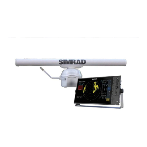
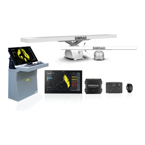
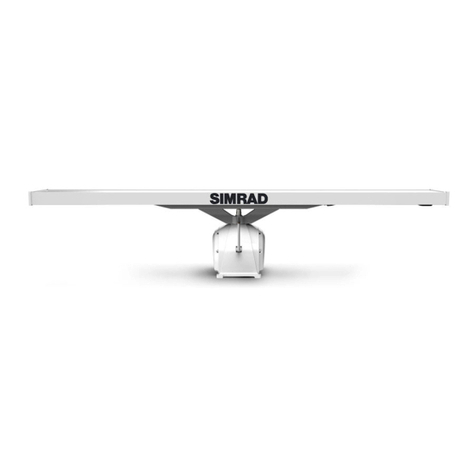
Simrad HALO 2000 Series User manual

www.simrad-yachting.com
HALO®2000 SERIES and
HALO®3000 SERIES pulse
compression radars
INSTALLATION MANUAL
ENGLISH

PAGE | 2

PAGE | 3
Disclaimer
This product is not a substitute for proper training and prudent seamanship. It is the owner’s sole
responsibility to install and use the equipment in a manner that will not cause accidents, personal
injury or property damage. The user of this product is solely responsible for observing maritime
safety practices.
Navigational features that appear in this guide are not a substitute for proper training and
prudent seamanship. They do not replace a human navigator and SHOULD NOT be relied on as a
sole or primary source of navigation. It is the operator’s sole responsibility to use more than one
navigational method to ensure the route suggested by the system is safe.
NAVICO HOLDING AS AND ITS SUBSIDIARIES, BRANCHES AND AFFILIATES DISCLAIM ALL LIABILITY
FOR ANY USE OF THIS PRODUCT IN A WAY THAT MAY CAUSE ACCIDENTS, DAMAGE OR THAT MAY
VIOLATE THE LAW.
This manual represents the product as at the time of printing. Navico Holding AS and its
further assistance.
Governing language
This statement, any instruction manuals, user guides and other information relating to the product
(Documentation) may be translated to, or has been translated from, another language (Translation).
Copyright
Copyright © 2022 Navico Holding AS.
Warranty
The warranty card is supplied as a separate document.
In case of any queries, refer to the brand website of your display or system:
www.simrad-yachting.com.
Declarations and conformance
This equipment is intended for use in international waters as well as coastal sea areas administered
by countries of the E.U. and E.E.A.
Compliance statements
Declarations
The relevant declarations of conformity are available on the following website within the radar’s
documentation section: www.simrad-yachting.com.
United Kingdom
Simrad®HALO®2000 SERIES and HALO®3000 SERIES pulse compression radars comply with UKCA
under The Radio Equipment Regulations 2017.
The Simrad HALO®RI-50 interface module complies with UKCA under The Electromagnetic
Compatibility Regulations 2016.
Europe
Simrad®HALO®2000 SERIES and HALO®3000 SERIES pulse compression radars comply with CE
The Simrad®HALO®

PAGE | 4
United States of America
THIS DEVICE COMPLIES WITH PART 15 OF THE FCC RULES. OPERATION IS SUBJECT TO THE
FOLLOWING TWO CONDITIONS: (1) THIS DEVICE MAY NOT CAUSE HARMFUL INTERFERENCE, AND
(2) THIS DEVICE MUST ACCEPT ANY INTERFERENCE RECEIVED, INCLUDING INTERFERENCE THAT
MAY CAUSE UNDESIRED OPERATION.
⚠Warning: Navico is not responsible for any changes or modications not expressly
approved by the party responsible for compliance. Such modications could void the
user’s authority to operate the equipment.
RF emissions notice
This equipment complies with FCC radiation exposure limits set forth for an uncontrolled
environment. This device’s antenna must be installed in accordance with provided instructions, and
it must be operated with a minimum spacing of 177.97 cm (5.84 ft) for the HALO®3000 SERIES and
106 cm (3.48 ft) for the HALO®2000 SERIES between the antenna and a person’s body (excluding
extremities of hands, wrist and feet). Be aware that these FCC safety distances are calculated for a
non-rotating antenna that is transmitting. For radio frequency safe distances for an antenna that is
rotating and transmitting, see the Radio frequency (RF) safe distances table on the next page of
this manual.
¼Note: This equipment has been tested and found to comply with the limits for a Class B digital
device, pursuant to part 15 of the FCC Rules. These limits are designed to provide reasonable
protection against harmful interference in a residential installation. This equipment generates,
uses and can radiate radio frequency energy and, if not installed and used in accordance with
the instructions, may cause harmful interference to radio communications. However, there is no
guarantee that interference will not occur in a particular installation. If this equipment does cause
harmful interference to radio or television reception, which can be determined by turning the
equipment o and on, the user is encouraged to try to correct the interference by one or more of
the following measures:
• Reorient or relocate the receiving antenna.
• Increase the separation between the equipment and receiver.
• Connect the equipment into an outlet on a circuit dierent from that to which the receiver is
connected.
• Consult the dealer or an experienced radio/TV technician for help.
¼Note: HALO®2000 SERIES and HALO®3000 SERIES radars don’t transmit when the antenna isn’t
rotating, so pose not risk in this situation.
Canada
English
This device complies with Innovation, Science and Economic Development Canada license-exempt
RSS standard(s). Operation is subject to the following two conditions: (1) this device may not cause
interference, and (2) this device must accept any interference, including interference that may
cause undesired operation of the device.
Français
Le présent appareil est conforme aux Innovation, Sciences et Développement économique Canada
(ISDE) applicables aux appareils radio exempts de licence. L’exploitation est autorisée aux deux
conditions suivantes : (1) l’appareil ne doit pas produire de brouillage, et (2) l’utilisateur de l’appareil
doit accepter tout brouillage radioélectrique subi, même si le brouillage est susceptible d’en
compromettre le fonctionnement.
Innovation, Science and Economic Development Canada (ISED) statement
English
Under ISED regulations, this radio transmitter may only operate using an antenna of a type
and maximum (or lesser) gain approved for the transmitter by ISED. To reduce potential radio
interference to other users, the antenna type and its gain should be so chosen that the equivalent
isotropically radiated power (e.i.r.p.) is not more than that necessary for successful communication.
PAGE | 5
The radio transmitters, 978B-HALO2000 and 978B-HALO3000, have been approved by Innovation,
Science and Economic Development Canada to operate with the antenna types listed below with
the maximum permissible gain and required antenna impedance for each antenna type indicated.
Antenna types not included in this list, having a gain greater than the maximum gain indicated for
that type, are strictly prohibited for use with this device.
Français
Conformément à la réglementation d’Innovation, Sciences et Développement économique Canada
(ISDE), le présent émetteur radio peut fonctionner avec une antenne d’un type et d’un gain maximal
(ou inférieur) approuvé pour l’émetteur par Industrie Canada. Dans le but de réduire les risques
de brouillage radioélectrique à l’intention des autres utilisateurs, il faut choisir le type d’antenne et
son gain de sorte que la puissance isotrope rayonnée quivalente (p.i.r.e.) ne dépassepas l’intensité
nécessaire à l’établissement d’une communication satisfaisante.
Les présents émetteurs radio, 978B-HALO2000 et 978B-HALO3000, ont été approuvés par
Innovation, Sciences et Développement économique Canada (ISDE) pour fonctionner avec les
types d’antenne énumérés ci-dessous et ayant un gain admissible maximal et l’impédance requise
pour chaque type d’antenne. Les types d’antenne non inclus dans cette liste, ou dont le gain est
supérieur au gain maximal indiqué, sont strictement interdits pour l’exploitation de l’émetteur.
HALO®
antennas
Description Max. permissible
antenna gain (dBi)
Impedance
000-11464-001 Antenna, 3 ft, HALO®26 50 Ohm (WR-90 waveguide)
000-11465-001 Antenna, 4 ft, HALO®27.2 50 Ohm (WR-90 waveguide)
000-11466-001 Antenna, 6 ft, HALO®29 50 Ohm (WR-90 waveguide)
Radio frequency (RF) safe distances
Figures in the table below show the radio frequency radiation safe distance for an operating
(rotating) antenna is within the antenna’s turning circle. Irrespective, users should stay well outside
the turning circle of the antenna to avoid injury through physical impact as it spins.
System 100 W / m2occupational
safe distance
10 W / m2public safe distance
HALO®2000 SERIES radars Within antenna turning circle 1.5 m (4.9 ft)
HALO®3000 SERIES radars 0.8 m (2.6 ft) 2.5 m (8.2 ft)
Trademarks
®
for Navico Holding AS and other entities.
• Navico®
• Simrad®
Navico Holding AS.
• HALO®
•
•
•
•
•
•
•
•
•

PAGE | 6
•
•
•
•
• NMEA 2000®
• Tef-Gel®
About this manual
This manual is a reference guide for installing the Simrad®HALO 2000 SERIES and HALO 3000
website: www.support.simrad-yachting.com.
Intended audience
to:
•
• nautical terminology and practices.
Translated manuals
Translated versions of this manual can be found on the website: www.simrad-yachting.com.

PAGE | 7
CONTENTS
8 Introduction
9 Check the parts
11 Tools required
12 Installation guidelines
17 Hardware mounting
26 Wiring
39 Setup and conguration
41 Upgrading
44 Specications
47 Drawings
50 Parts list

PAGE | 8
INTRODUCTION
This manual explains how to install the latest generation of HALO open array, pulse compression
radars – the HALO 2000 SERIES and HALO 3000 SERIES.
This manual should be used in conjunction with the installation manual provided with your multi-
function display. It is written for professional marine technicians, installation technicians and service
technicians. Dealers may use information contained in this document.
HALO 2000 SERIES and HALO 3000 SERIES radars combine the best characteristics of traditional
pulse and FMCW broadband radar systems. Pulse compression technology provides an
Solid state technology means minimal warm-up time and maximum ocean-going reliability.
This latest generation of HALO open array radars incorporate updated hardware and mechanical
design improvements that deliver increased power, improved long-range target detection
performance and more system reliability.
HALO 2000 SERIES and HALO 3000 SERIES radar systems consist of a pedestal, antenna, RI-50
¼Notes:
• HALO 2000 SERIES and HALO 3000 SERIES radar systems are available with antennas in three
sizes: 3 ft, 4 ft and 6 ft.
• ®GO
®R2009 and R3016 radar control units.
Warnings
⚠
the navigation information received from your radar with data from other navigation aids and
A CAREFUL NAVIGATOR NEVER RELIES ON ONLY ONE METHOD TO OBTAIN NAVIGATION
INFORMATION.
International Regulations for Preventing Collisions at Sea mandate that when radar is on
a vessel, the radar must be used at all times, regardless of weather conditions or visibility.
Numerous court decisions have ruled that the radar must be used, and the radar operator must
liability if an accident occurs.
⚠High current, stored and microwave energy hazard. Technicians must exercise extreme care
radar. Before touching any high voltage components, ground them with a clip lead.
⚠The radar’s blue 4-level static accent pedestal lighting may not be approved for use in your
lights ON.
⚠The microwave energy radiated by a radar antenna is harmful to humans, especially the eyes.
radar.

PAGE | 9
CHECK THE PARTS
Pedestal
1 2 3 4
6
a
b
cde
78
5
1Radar pedestal
2Interconnection cable 20 m (65 ft). Other lengths are available from your nearest Simrad®
dealer.
3Lifting strap
4
5Tef-Gel anti-seize, anti-corrosion gel
6Mounting bolts and washers
x 4
x 4
x 4
x 4
e) Plastic isolating washer, M12 x 38 x 8
7Mounting template
8This manual

PAGE | 10
Antenna
1
2
3
4
1Radar antenna
2 x 4
3 x 4
4 x 4
RI-50 radar interface module
1 2 3 4
5 6 7
1RI-50 radar interface module
24-way connector for the pedestal interconnection cable
32-way connector for the pedestal interconnection cable
4
5 x 4
6
7

PAGE | 11
TOOLS REQUIRED
4
3
2
1
8
7
6
5
910 11
1Drill
2Torque wrench
3
4
5
6
7Screwdriver (Pozidriv, PZ2) for RI-50 mounting screws
8Screwdriver (Phillips, #1) for RI-50 circuit board cover screws
9
10
11

PAGE | 12
INSTALLATION GUIDELINES
⚠Warning: A radar should only be installed by a qualied marine technician, as
improper installation poses risks to the installer, the public, and to the safety of the
vessel.
⚠Warning: Before starting the installation or any maintenance on a HALO 2000 SERIES
or HALO 3000 SERIES radar, make sure the service mode switch at the back of the
pedestal is set to 0 (power supply disabled).
familiar with this type of electronics, consult a trained service or installation technician before trying
to service any part of the equipment.
Installation includes:
• hardware mounting
• electrical wiring
•
• adjusting the radar for proper performance.
The radar’s ability to detect targets depends greatly on its location. The ideal location is high above
A higher installation location improves the radar’s ranging distance, but it also increases the range
When you are deciding on the location, consider the following:
•
A longer 30 m (98 ft) cable is available. 30 m (98 ft) is the longest the cable that can be used.
• If the roof of the wheelhouse is the highest existing location, consider installing a radar mast
or tower on which you can mount the radar.
• If you install the radar on the mast, position it on the forward side so there is a clear view to
the front of the vessel.
•
What not to do
• Do not install the radar too high, where its weight may compromise the stability of the vessel
and degrade the radar picture over short ranges.
•
•
display.
•
VHF antennas and GPS equipment, as it may cause interference.
• Do not install the radar where may be subjected to strong vibrations that could degrade its
performance.
•
the antenna and jam it.

PAGE | 13
Compass safe distance
Do not install your HALO radar or RI-50 inside of the recommended safe distances of navigational
HALO 2000 SERIES and HALO 3000 SERIES pedestal
Antenna Compass Safe distance
Standard load Standard 1.0 m (3.3 ft)
Standard load 0.5 m (1.6 ft)
RI-50 interface module
Compass Safe distance
Standard 0.1 m (0.33 ft)
0.1 m (0.33 ft)
Multi-radar installations
Do not install your HALO 2000 SERIES or HALO 3000 SERIES radar on the same horizontal beam
plane as any other radar. Separate them vertically by at least 2 m (6.6 ft).
2 m (6.6 ft)
2 m (6.6 ft)
11
2
3
1HALO 2000 SERIES or HALO 3000 SERIES radar
2Conventional pulse radar or another HALO 2000 SERIES or HALO 3000 SERIES radar
3HALO 20, 20+ or 24 dome radar
¼Note: Possible interference can be reduced using the radar’s sector blanking setting on your multi-
function display.
Power boat installations

PAGE | 14
If you install your HALO radar on a power boat with a steep planing angle, it is recommended you
tilt the radar angle down at the front.
¼Note: Optional 4° base wedges are available from third-party suppliers.
Considerations for roof mounting
When deciding a suitable mounting location for your HALO radar, be aware that the vertical radar
beam extends to 25° either side of horizontal, with 50% of the emitted energy projecting in a beam
12.5° either side of horizontal.
If the radar beam cannot clear the roof line, this decreases the performance of the radar.
Depending on the size of the hard top of the vessel, we recommend you elevate the antenna to
ensure the radar beams clear the roof line.
Possible performance loss
25% of energy
50% of energy
25% of energy
12.5°
12.5°

PAGE | 15
Good performance
Best performance
For best performance, the radar should be positioned to allow the full beam to clear the
superstructure of the vessel.
¼Note: If the mounting surface is made of metal, you must elevate the radar so the beam has
complete clearance, otherwise its performance will be severely impaired.
A) from the
installation location of the radar to the furthest forward corner of your vessel’s hard top.
A
A
A

PAGE | 16
46 mm
92 mm
184 mm
230 mm
276 mm
138 mm
(1.81")
(3.62")
(7.24")
(9.06")
(9.69")
(5.43")
25°
1.8 m (6 ft)
2.0 m (6.5 ft)
2.2 m (7.2 ft)
2.4 m (7.8 ft)
2.6 m (8.5 ft)
2.8 m (9.1 ft)
3.0 m (9.8 ft)

PAGE | 17
HARDWARE MOUNTING
Install the RI-50 radar interface module
Install the RI-50 in a dry location away from spray, rain, drips, condensation or excessive heat. The
mounting position should be easily accessible.
Always mount the RI-50 vertically, with the cable entry points facing downwards. This helps with
cooling and helps prevent any water from entering the cable grommets.
Ensure there is enough unobstructed space above and below the RI-50 to ensure it cools
adequately and the ambient temperature does not exceed 55°C (131°F). If overheating is a
concern, consider additional ventilation, such as a vent or extraction fan.
⚠Warning: Inadequate ventilation and subsequent overheating of the unit may cause
unreliable operation and reduced service life.
The RI-50 must be located where it can easily connect to the vessel’s ground connection, the
pedestal interconnection cable and the power cable.
Use fasteners suited to the mounting surface material. If you are using the supplied self-tapping
tapping screws, reinforce it or use machine screws, nuts and washers. Use only 304 or 316 stainless
steel fasteners.

PAGE | 18
Run the interconnection cable
The 14-pin connector end of the cable connects to the pedestal. The RJ45 connector connects to
the RI-50 radar interface module.
1
hole to pass the 14-pin connector from the RI-50 to the pedestal.
2 To protect the connectors, especially the RJ45 connector, when pulling the cable through the
3
4 Tape the wires and the RJ45 connector to the mouse line so they do not get caught and bend
AB B
C
AMouse line
BElectrical tape
CCable tie
5 Carefully pull the interconnection cable through the vessel so it runs between the RI-50 radar
interface module and your chosen pedestal location.
Install the pedestal
⚠Warning: Leave the waveguide protection cap on the pedestal while you mount it
to your vessel. You should only remove the cap just before you t the antenna to the
pedestal.
Bolts and washers
•
•
If using longer bolts, ensure they are marine-grade stainless steel and allow for a minimum of
⚠Important: Apply a light coating of the supplied Tef-Gel®or other suitable nickel- or
PTFE-based lubricant to the mounting bolts to prevent galling and corrosion.

PAGE | 19
If you are installing the pedestal onto a steel surface, also use the supplied plastic isolating
washers.
Surface mount: rear cable connection
1 Place the mounting template in your desired installation location, observing the correct
orientation.
¼Note: You can compensate for any minor deviations in orientation later by using the radar’s
bearing alignment setting on your multi-function display.
2
3 Tape the template securely in place.

PAGE | 20
4
mounting template.
5 Remove the mounting template .
6 Apply the supplied Tef-Gel®anti-corrosion gel to the four feet of the pedestal.
7 Lift the pedestal using the supplied lifting strap.
⚠Warning: Do not lift the pedestal with the antenna attached.
8 Lower the pedestal carefully so its mounting holes align with the drilled holes in the vessel.
9
¼Note: If you are installing the pedestal onto a steel surface, also use the supplied plastic isolating
washers.
10 Apply the Tef-Gel®anti-corrosion gel to the threads of each bolt.
This manual suits for next models
4
Table of contents
Other Simrad Radar manuals

Simrad
Simrad ARGUS FMCW 3G User manual

Simrad
Simrad 6kW User manual

Simrad
Simrad R3016 12U/6X User manual

Simrad
Simrad argus Manual

Simrad
Simrad Halo 000-11468-001 Reference guide

Simrad
Simrad R5000 User manual

Simrad
Simrad R2009 Reference guide

Simrad
Simrad R5000 Quick start guide

Simrad
Simrad ARGUS FMCW 3G User manual

Simrad
Simrad SRT User manual
Popular Radar manuals by other brands

Houston Radar
Houston Radar DR600 User manual and installation guide

Endress+Hauser
Endress+Hauser Micropilot FMR53 technical information

WABCO
WABCO OnGuard installation instructions

Endress+Hauser
Endress+Hauser Micropilot FMR63B PROFIBUS PA operating instructions

JRC
JRC JMA-933B installation manual

CAME
CAME 001SIRCWWL manual