Simrad R5000 Quick start guide

ENGLISH
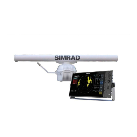
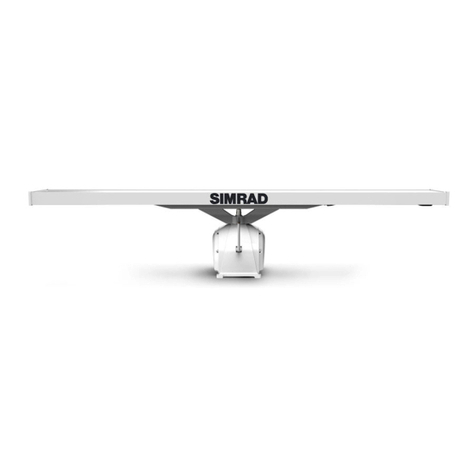
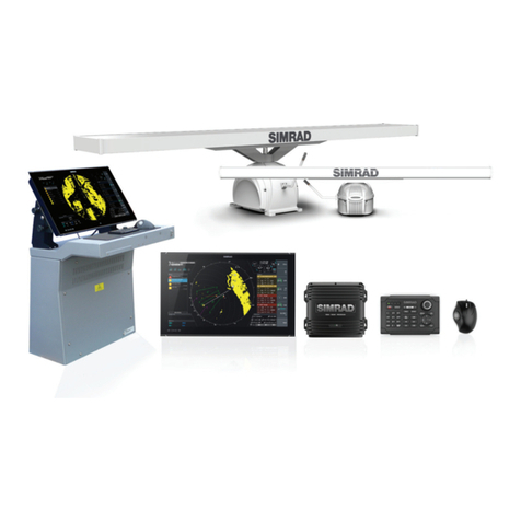
R5000 Radar system
Commissioning Manual
www.navico-commercial.com


Preface
Disclaimer
As Navico is continuously improving this product, we retain the right to make changes to the
product at any time which may not be reflected in this version of the manual. Please contact
your nearest distributor if you require any further assistance.
It is the owner’s sole responsibility to install and use the equipment in a manner that will not
cause accidents, personal injury or property damage. The user of this product is solely
responsible for observing maritime safety practices.
NAVICO HOLDING AS AND ITS SUBSIDIARIES, BRANCHES AND AFFILIATES DISCLAIM ALL
LIABILITY FOR ANY USE OF THIS PRODUCT IN A WAY THAT MAY CAUSE ACCIDENTS, DAMAGE
OR THAT MAY VIOLATE THE LAW.
This manual represents the product as at the time of printing. Navico Holding AS and its
subsidiaries, branches and affiliates reserve the right to make changes to specifications
without notice.
Governing language
This statement, any instruction manuals, user guides and other information relating to the
product (Documentation) may be translated to, or has been translated from, another
language (Translation). In the event of any conflict between any Translation of the
Documentation, the English language version of the Documentation will be the official
version of the Documentation.
Copyright
Copyright © 2021 Navico Holding AS.
Trademarks
®Reg. U.S. Pat. & Tm. Off, and ™ common law marks. Visit www.navico.com/intellectual-
property to review the global trademark rights and accreditations for Navico Holding AS and
other entities.
•Navico® is a trademark of Navico Holding AS.
•SIMRAD® is a trademark of Kongsberg Maritime AS, Licensed to Navico Holding AS.
Warranty
The warranty card is supplied as a separate document. In case of any queries, refer to the
brand website of your unit or system:
www.navico-commercial.com
Compliance statements
Europe
Navico declare under our sole responsibility that the product conforms with the
requirements of:
•European Council Directive 2014/90/EU on Marine Equipment modified by Commission
Implementing Regulation (EU) 2020/1170 (16 July 2020) - Wheelmark
ÚNote: The unit(s) are Wheelmark approved only when installed according to the relevant
MED-B certificate.
Declarations
The relevant declarations of conformity and certificates are available at:
www.navico-commercial.com
Preface | R5000 Commissioning manual 3

About this manual
Intended audience
The manual assumes that the reader has basic knowledge about this type of equipment with
regards to:
•commissioning of complex radar systems
•nautical terminology and practices
Important text conventions
Important text that requires special attention from the reader is emphasized as follows:
ÚNote: Used to draw the reader’s attention to a comment or some important information.
Warning: Used when it is necessary to warn personnel that they should
proceed carefully to prevent risk of injury and/or damage to equipment/
personnel.
Software version
You can view the software version installed on the unit in the about dialog:
The manual will continuously be updated to match new software releases. The latest
available manual version can be downloaded from the product website on:
www.navico-commercial.com
Change log
Part no Date and description
988-12293-001 2018-Sept-19
First version.
988-12293-002 2018 - Nov-01
Updated to match software release.
988-12293-003 2021-July-25
Updated to add LWE information.
4Preface | R5000 Commissioning manual

Safety precautions
Safety precautions described in this section are applicable to the radar system. They are
general safety precautions that are not related to any specific procedure, and they might
therefore not appear elsewhere in this manual. They are recommended precautions that
personnel must understand and apply during operation and maintenance of the system.
You are obliged to read these operating instructions prior to operation, and to adhere to the
operating instructions in order to prevent possible danger. Prevention of danger includes
that operator personnel are trained and authorized for safe operation of the equipment. We
assume no liability for damage due to improper operation which could have been
prevented.
The system must only be operated by persons who have passed the relevant mandatory
training on the respective systems and applications. Only reading these operating
instructions cannot replace such training. Persons authorized to operate, maintain and
troubleshoot the system are instructed and trained by Simrad. Persons operating or servicing
this radar system must be familiar with the general safety regulations and specific safety
systems, and they must have passed all required training. They must have read the relevant
operating instructions and manuals before starting to work.
Have these operating instructions always at hand on all relevant locations, and ensure that
copies are available to all operators. Operating personnel must at all times follow all safety
regulations.
During normal operation, the unit can be quickly disconnected from the main power line by
turning OFF the relevant circuit breaker located on the electric switchboard.
Do not replace components or make adjustments inside the unit when the voltage supply is
turned ON. Always remove power and discharge to ground a circuit before touching it.
Under no circumstances should any person initiate servicing or repairing the unit except in
the presence of a qualified person.
Ensure unobstructed access to all operator panels, controls, and relevant switchgear cabinets
in order to enable instant response to alarms.
Whenever it is necessary to disconnect the waveguide from a radar transmitter for
maintenance purpose, the transmitter output should be terminated with a matched load. If
this is not possible, care should be taken. Do not stand in front of an open-ended waveguide
from which power is being radiated.
ÚNote: Main power is always present on the terminal board unless the main break from
the power distribution panel of the vessel is turned off.
Warning: Never look down a waveguide from which power is being
radiated!
Warnings
High voltage
Radar equipment includes high voltage that can cause injury or loss of life. Danger exists only
when the units are opened, exposing internal circuits, as when servicing the equipment.
This radar has been carefully designed to protect personnel from possible injury from high
voltages. Although every effort has been made to eliminate danger to personnel, no
responsibility is accepted for any injury or loss of life suffered in connection with this
equipment.
Radio frequency radiation
Harmful effects (particularly to the eyes) may be caused by exposure of any part of the
human body to high power radio frequency radiation.
However, the system is designed to always disable the microwave radiation when the
antenna is not rotating.
Preface | R5000 Commissioning manual 5

Hazard distances
Configuration Distance 100 W/m2
point (m)
Distance 50 W/m2
point (m)
Distance 10 W/m2
point (m)
12 KW Transceiver
6' X-band Antenna - 0.15 0.6
12 KW Transceiver
9' X-band Antenna - - 0.5
12 KW Transceiver
12' X-band Antenna - - 0.35
25 KW Transceiver
6' X-band Antenna 0.1 0.2 1.3
25 KW Transceiver
9' X-band Antenna - 0.1 1.0
25 KW Transceiver
12' X-band Antenna - 0.05 0.9
30 KW Transceiver
12' S-band Antenna - - 0.4
X-Ray radiation
This radar system does not generate X-ray radiation.
6Preface | R5000 Commissioning manual

Contents
8 Operating the system
8O5000 trackball mouse keys
9 O2000 front controls
10 M5000 monitor keys
11 Basic operation
11 Turning the system ON and OFF
11 Adjusting display brightness
11 Selecting radar source
11 Switching the sensor between transmit and standby mode
12 The user interface
12 Main panel
13 Picture freeze indicator
13 Quick access buttons
13 Main menu and submenus
14 On-screen keyboard
15 Software setup
15 Overview
16 Introduction to Lightweight Ethernet
16 The settings dialog
17 Configuring the O2000
18 System settings
19 Radar settings
26 Position settings
27 Alerts settings
27 Units of measure settings
27 Network settings
35 Own ship
37 Simulator
37 Introduction
37 Demo mode
37 Simulator source files
37 Advanced simulator settings
39 Menu overview
39 Main menu
40 Settings menu
42 O2000/O5000 Trackball, key function comparison
43 Terms and abbreviations
Contents | R5000 Commissioning manual 7

Operating the system
The system is operated by the remote control unit (O2000) and by the mouse (O5000
Trackball unit).
The remote controller is used for menu operation, and for easy operation of the quick access
buttons.
The mouse is mainly used for managing targets, and in situations where it is required to
position the cursor accurately on the PPI.
O5000 trackball mouse keys
The optical trackball (A) is used for positioning the cursor. The other mouse keys have
different functionality depending on the position of the cursor on the radar panel.
The following table lists the key functions relative to the part of the radar panel that is under
the cursor.
ÚNote: The cursor must be located over an open menu or over the quick access pop-up
to be able to use the scroll function.
Cursor over ... Left key (B) Right key (C) Scroll wheel (D)
Menu Select Return to previous
menu level
•Rotate to scroll
menu options
•Press to select
Quick access button Select Display selected
button's pop-up
•Rotate to scroll
pop-up options
AIS target Activate/deactivate Display target menu No action
Radar target Acquire target
1
8Operating the system | R5000 Commissioning manual

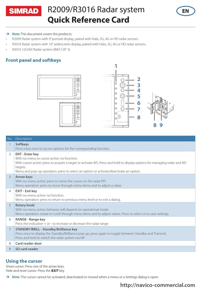
O2000 front controls
ÚNote: The O2000 can be used with different equipment. As noted below, some of the
keys are not applicable for the R5000.
AMark/MOB key. Not used for R5000
BUnit under command LEDs. Not used for R5000
CDisplay key. Used for configuration of the O2000. Not used for operating the R5000
DEBL/VRM key. Press once to toggle EBL/VRM markers On/Off. Re-press to display
the EBL/VRM pop-up. Press and hold to toggle between EBL/VRM 1 and EBL/VRM
2.
ETrails key. Press to toggle trails ON/OFF.
FRange key. Press the + or the - indication to increase or decrease the radar range
GOffset key. Press once to display the Offset menu
HEnter key. No cursor on PPI: no action. Cursor on PPI: press to activate/deactivate
AIS, press and hold to display the targets menu.
Menu operation: press to select an option
IRotary knob. With no menu active: behavior depending on operational mode.
Menu operation: rotate to scroll through menu items and to adjust values, press to
select or to save settings
JExit key. With no menu active: clear the cursor from the PPI. Menu operation: press
to return to previous menu level or to exit a dialog
KArrow keys. With no menu active: press to move the cursor on the radar PPI.
Menu operation: press to move through menu items and to adjust a value
LView key. Press once to display the View menu
MMenu key. Press once to display the Main menu
NGain, Sea, and Rain keys. Press to set radar sensitivity
OAcknowledge key. Press once to acknowledge the most recent alarm or warning in
the Alerts panel. Press the key again to acknowledge the next alarm or warning.
Press and hold to bring the focus on the Alerts panel without acknowledging the
most recent alarm
PAIS key. Press to activate/deactivate AIS information on screen. Press and hold to
display the Vessels dialog
QStandby/Brilliance key. Press once to display the Standby/Brightness pop-up. Press
twice to toggle between Standby and Transmit. Press and hold to switch the radar
system ON/OFF.
RMode key. Not used for R5000
SAlpha numeric keypad. Used for entering numbers or text in dialog boxes. With no
menu active: press a key to modify the range as shown below:
Operating the system | R5000 Commissioning manual 9

1234567890
NM 1/8 1/4 1/2 3/4 1.5 3 6 12 24 48
M5000 monitor keys
The monitor is configured and controlled using the row of touch sensitive buttons along the
lower edge of the monitor frame. All buttons are backlit - only the power button is
illuminated when the monitor is turned off.
A Power key
•With OSD (On Screen Display) menu active: press to return to previous menu
level
•With no OSD menu action: no action
B Brilliance adjustment key
•Press plus/minus key to decrease/increase brightness (no on-screen display of
brightness level)
•Simultaneously press and hold both keys to reset the brightness level to default
value. The default value is set in the OSD menu
•With OSD menu active: press plus/minus key to move focus up/down in the
menu
C Enter key
•With OSD menu active: press to confirm a selection
•With no OSD menu active: no action
D Red LED
•Solid on: standby mode, or no video source
•Flashing: monitor booting or upgrading
E Menu key
•Press and hold to activate the OSD menu
For more information, refer to the separate documentation for the monitor.
10 Operating the system | R5000 Commissioning manual

Basic operation
Turning the system ON and OFF
Turning ON
Press the standby/brilliance key to turn the system ON.
The system will be ON as long as power is connected.
Switching the system to standby mode
Press and hold the standby/brilliance key to turn the R5000 radar processor and the monitor
to standby mode. The radar sensor is turned into standby mode only if R5000 is controlling it
(connected as master). If it is in slave/clone mode, the sensor will continue transmitting.
Adjusting display brightness
The brilliance is adjusted from the brilliance pop-up.
•Display the pop-up by pressing the standby/brilliance key, then adjust the display
brilliance by turning the rotary knob.
At first start-up, the display brilliance is set to 100%. When the unit is restarted, the brilliance
is automatically set to the level it was prior to switching the unit off.
The system includes a day and a night color palette. When the brilliance is set to 40% or
lower, the system switches to use the night palette.
•With the pop-up open, switch between the day and night palette by pressing the left
(40%) or right (100%) arrow keys.
Close the pop-up by pressing the exit key.
Selecting radar source
More than one radar sensor can be connected to the radar control unit.
Select the active radar sensor from the main menu.
Switching the sensor between transmit and standby mode
You switch between transmit and standby mode when the brilliance pop-up is displayed.
•Display the pop-up by pressing the standby/brilliance key, then repeat short presses on
the key to switch between standby and transmit mode
2
Basic operation | R5000 Commissioning manual 11

The user interface
Main panel
The main panel is divided into predefined areas as shown in the figure below.
A Plan Position Indicator (PPI)
Radar video area where all tracking and navigation options are performed.
B Own ship information
Stabilization mode indicator, picture freeze indicator and gauges showing primary
and secondary sensors.
C Target panel
Detailed information about selected targets and AIS targets.
D Quick access buttons
Dedicated buttons for main function.
E Target indicators
Overview of target indicator settings.
F Markers
Details for active VRM and EBL markers.
G Cursor information
Range and bearing from the vessel to the cursor position. Also including position
information if a position source is available.
H Alerts panel
List of all active alerts.
I Signal indicators
Gauges for signal processing and indicators for radar functions.
J System information
Range, mode and pulse details.
3
12 The user interface | R5000 Commissioning manual

Picture freeze indicator
The image includes a picture freeze indicator (A). The small dot blinks at an interval of 1
second to show that the screen is alive and that information from sensors is updated.
If the picture freezes the unit needs to be restarted.
Quick access buttons
The quick access buttons are activated from the dedicated keys on the controller, or by using
the mouse to select the button.
More details about the quick access buttons are available in the separate sections describing
the functions later in this manual.
Quick access pop-ups
Some of the quick access buttons have additional functions, presented as a pop-up.
To display the pop-up:
•Double-press the dedicated key on the controller
•Press the right mouse key when the cursor is over a selected quick access button
To remove the pop-up and revert to the button's main function:
•Press the exit key on O2000
•Press the left mouse key when the cursor is outside the pop-up
•Press the right mouse key when the cursor is over the pop-up
Main menu and submenus
You access the main menu by pressing the menu key, or by selecting the quick access menu
button.
To operate the menu with the O2000:
•Press the up and down arrow keys or turn the rotary knob to move up and down in a
menu
•Press the enter key, the right arrow key or the rotary knob to access a submenu, to toggle
options or to confirm a selection
•Press the exit key or the left arrow key to return to previous menu level and then exit the
menu system
Some options display a slider. Turn the rotary knob or press the up/down arrow keys to
adjust the value.
To use the trackball mouse to operate the menu:
•Use the scroll wheel to move up and down in a menu
•Use the left key to access a submenu, to toggle options or to confirm a selection
•Use the right key to return to previous menu level and then exit the menu system
ÚNote: The cursor must be located over the menu to operate the menu system.
The user interface | R5000 Commissioning manual 13

On-screen keyboard
A numeric or alphanumeric virtual keyboard is displayed when required to enter user
information in dialogs.
To enter text:
•Use the arrow keys to locate the cursor over a virtual key, then confirm the selection with
enter key
•Select a virtual key with the left mouse key
If the virtual keyboard is inactive for 10 seconds it will automatically close.
Complete the entry and close the dialog by selecting the virtual enter key.
Remove the virtual keyboard without saving by pressing the exit key.
14 The user interface | R5000 Commissioning manual

Software setup
Overview
Prior to use, the system requires a number of settings be configured in order for the system
to perform as expected.
Most settings are intended to be configured by the technician commissioning the system, by
the operator at first use, or by a technician after servicing or replacement of system parts.
Other settings are generic, and the system can be used with default values.
The installation settings are only available in service mode. Refer to "The settings dialog" on page
16 and "Access control" on page 16.
ÚNote: Before starting the software setup, the system must be wired according to the
wiring instructions. All system units must be powered on. The O5000 Trackball must be
connected. All sensors must be available. At least one transceiver must be assigned to
one control station in the priority table. Refer to "Priorities table" on page 29
All the areas listed must be addressed during commissioning, and they should be stepped
through in the listed sequence.
When the setup is completed, the R5000 processor must be restarted. Refer to "Reboot device"
on page 19.
The settings are split between:
•control station settings: need to be done for each of the control stations in a multi-station
installation
•shared settings: can be done from any control station in the system
NMEA 0183 equivalence with IEC 61162-1/2
This device uses the term NMEA 0183 in menus and dialogs. NMEA 0183 is equivalent with
the IEC standard IEC 61162-1/2.
Control station settings
Control station settings are local settings for the control station. They need to be repeated for
each of the control stations in a multi-station installation.
1O2000 configuration "Configuring the O2000" on page 17
2Setting up the NMEA 0183 ports "NMEA 0183 setup" on page 31
3Selecting sources "Sources" on page 28
4LWE Own configuration "LWE Own configuration" on page 32
Shared settings
The settings listed are shared for the complete radar installation. These can be done from any
control station in the system.
1Radar settings
•Radar sensor installation settings "Installation settings" on page 20
2Own ship settings
•Own ship setup "Own ship setup" on page 35
•Own ship's AIS MMSI number "MMSI" on page 35
•Trial maneuver setup "Trial maneuver settings" on page 36
3Control station settings
•Control station names "Control stations" on page 28
4
Software setup | R5000 Commissioning manual 15

•Control stations priority "Priorities table" on page 29
Introduction to Lightweight Ethernet
Lightweight Ethernet (LWE), defined by IEC61162-450, is a protocol defined to enable an
Ethernet connection between multiple talkers and multiple listeners, using the messages
defined in IEC61162-1/2. LWE is an IP-based implementation, making use of a multicast
address and corresponding User Datagram Protocol (UDP) port for transmission. LWE is
essentially a means to share data between units over Ethernet.
There are some restrictions on the connection of LWE networks:
•The different components are connected through an Ethernet switch, and connection to
a router or repeater hubs are not allowed
•No multicast filtering is configured
Equipment on the network that performs system functions can transmit and receive
information. Each System Function (SF) is identified by a System Function Identifier (SFI)
which is unique on any boat network.
ÚNote: If no SFI is entered (remaining with the default 9999 value), the device will not be
visible on the LWE network, and it will not share any data.
Every device that is a part of the LWE network shall be assigned an IP address (10.0.0.1 to
10.255.255.253 or 192.168.0.1 to 192.168.255.254). This IP address is to be chosen as a unique
address for every device on the boat network.
The settings dialog
The system setup is done from the settings dialog.
Access control
Some of the parameters in the settings dialogs are intended for system setup and service
engineers. These parameters are protected, and they are only available by entering the
password QWERTY.
16 Software setup | R5000 Commissioning manual

When the password is entered, service mode is enabled and all settings are accessible.
Warning: When in service mode, there is no timeout for the settings
dialogs, and the acoustic alert is disabled. Do not use the radar in service
mode during normal navigation.
Service mode is indicated on the radar PPI.
Service mode remains active until it is manually closed, or until the R5000 processor is
restarted or switched to standby mode.
Configuring the O2000
The O2000 controller has to be assigned to a radar control station before it can be used.
All LEDs on the O2000 controller are red when the unit is in unconfigured or in configuration
mode.
You assign and unassign an O2000 controller from the O2000 configuration dialog.
To activate the O2000 configuration dialog:
•Select the remote keyboard option from the settings dialog (A), then press and hold the
display key (B) on the O2000 controller until the O2000 configuration dialog (C) is
displayed
STANDBY
C
ABC DEF
GHI JKL MNO
PQRS TUV WXYZ
B
Software setup | R5000 Commissioning manual 17

ÚNote: The display key on the O2000 controller is only used for configuration. The
behavior described in the O2000 User manual is not relevant when used in an R5000
system.
Assigning the O2000 to a control station
With the O2000 configuration dialog open:
1. Press the 1, 2, 3 or 4 key on the O2000 to assign the radar control station to LED position 1,
2, 3 or 4 respectively
ÚNote: By default, a radar station is assigned to LED position 1. Other LED positions might
be used in a multiple radar installation where the LED can be used to indicate the
location (left to right) of the radar control station.
2. Select the assign button (A) to confirm your selection and to exit configuration mode
The assigned LED on the O2000 is now green to indicate that the unit is assigned to operate
the connected radar control station.
Un-assigning the O2000 control unit
With the O2000 configuration dialog open:
1. Press the 1, 2, 3 or 4 key on the O2000 controller to select the assigned LED position
2. Select the un-assign button (B) to un-assign the O2000 and to exit configuration mode
All LEDs on the O2000 are now red to indicate that the unit is not assigned to operate any
radar control station.
System settings
Key beeps
Controls the loudness of the beep sound when a key is pressed.
18 Software setup | R5000 Commissioning manual

Time
Configure time settings to suit vessel location, along with time and date formats.
Remote controller
Used for configuring the O2000 remote controller.
See details in "Configuring the O2000" on page 17.
Restore defaults
Restores selected settings to default factory values.
Files
File management system, used to browse the contents of the unit's internal memory and
storage devices connected to the unit.
Advanced
Used for detailed configuration of the user interface.
Reboot device
Used for rebooting the R5000 processor.
When this option is selected, the R5000 processor restarts and the radar sensor is switched to
standby mode. Other units in the radar system remains on.
Registration
Guidance for online registration of the device.
About
Displays copyright information, software version, and technical information for this unit.
Radar settings
Software setup | R5000 Commissioning manual 19

Installation settings
The radar system requires radar sensor specific settings in order to adjust for a number of
variables found in different installations.
ÚNote: The installation settings available depends on the radar sensor.
Radar source
In a system with more than one radar sensor, the device to configure is selected from this
menu.
Radar setup
Used for defining the radar sensor details.
Sensor name
Name of the radar sensor. The name is used to identify the radar sensor. The name is
displayed in the PPI center when no video signal is present and in several other tables and
Menu dialogs.
The text length is limited to maximum 10 characters.
Sensor description
Allows for more detailed description that could be useful to distinguish a radar sensor from
other radar sensors.
The text length is limited to maximum 250 characters.
If the information is added, the first 30 characters are shown on PPI when no video signal is
present.
20 Software setup | R5000 Commissioning manual
Other manuals for R5000
5
Table of contents
Other Simrad Radar manuals

Simrad
Simrad TXL-10S-4 User manual

Simrad
Simrad ARGUS FMCW 3G User manual

Simrad
Simrad R3016 12U/6X User manual

Simrad
Simrad argus Manual

Simrad
Simrad R5000 User manual

Simrad
Simrad HALO 2000 Series User manual

Simrad
Simrad ARGUS FMCW 3G User manual

Simrad
Simrad SRT User manual

Simrad
Simrad Halo User manual

Simrad
Simrad Halo 000-11468-001 Reference guide
Popular Radar manuals by other brands

Wavetronix
Wavetronix Expanse XP20 user guide

Traffic Logix
Traffic Logix SafePace 700 installation manual

Dahua
Dahua DH-PFR5QI-E60 user manual

Endress+Hauser
Endress+Hauser Levelflex FMP53 technical information

SYMEO
SYMEO STU product manual

Continental Refrigerator
Continental Refrigerator RightViu Mounting instructions