Simtronics MultiFlame DF-TV7-T User manual

Operating manual
NOSP16358-03 [0
4
/201
6
]
Optical Flame Detector
MultiFlame DF-TV7
DF-TV7-T Multi-spectrum IR
DF-TV7-V Combined UV/IR

MultiFlame DF-TV7 Page 2 / 56 NOSP16358-03 [04/2016]

MultiFlame DF-TV7 Page 3 / 56 NOSP16358-03 [04/2016]
N te
This manual must be carefully read by th se wh have r will have the resp nsibility f r the
perati n r maintenance f this pr duct. The pr duct may n t perf rm as designed if it is
n t used and maintained in acc rdance with the manufacturer’s instructi ns.
The warranties made by Simtr nics with respect t the pr duct are v ided if the pr duct is
n t used and maintained as described in this manual.
Please read the general warnings in chapter 9
© Simtr nics SAS, all rights reserved.

MultiFlame DF-TV7 Page 4 / 56 NOSP16358-03 [04/2016]
1. Pr duct Descripti n .................................................................................................................6
1.1. Applicati ns .......................................................................................................................6
1.2. DF-TV7-T: multi-spectrum IR ..........................................................................................7
1.3. DF-TV7-V: c mbined UV and IR .......................................................................................7
1.4. Technical specificati ns ...................................................................................................8
1.5. Detecti n Cartridge ..........................................................................................................9
1.6. Optical self-test functi n ..................................................................................................9
1.7. Wireless C nfigurati n T l.............................................................................................9
1.8. Pr duct C de...................................................................................................................10
2. Technical features ..................................................................................................................11
3. Perf rmances .........................................................................................................................14
3.1. Sensitivity ........................................................................................................................14
3.2. Field f View (C ne f Visi n) .........................................................................................15
3.3. False alarm immunity (FM 3260) ...................................................................................16
4. Installati n ..............................................................................................................................17
4.1. L cati n ...........................................................................................................................17
4.2. M unting ..........................................................................................................................18
4.3. Electric C nnecti n.........................................................................................................21
4.4. Detecti n cartridge .........................................................................................................27
5. C mmissi ning .......................................................................................................................29
5.1. Visual inspecti n .............................................................................................................29
5.2. P wer-up .........................................................................................................................29
5.3. Operati nal tests.............................................................................................................29
5.4. Using the LT15 test lamp ...............................................................................................30
6. Operati n.................................................................................................................................31
6.1. Envir nmental c nditi ns ..............................................................................................31
6.2. Inhibiti n ..........................................................................................................................31
6.3. Signal current l p .........................................................................................................32
6.4. P wer and fault indicati ns............................................................................................32
6.5. Alarm indicati n (LED) ...................................................................................................33
6.6. Wireless c mmunicati n t l TLU600 ..........................................................................33
6.7. Inf rmati n menu [INFO] ...............................................................................................36
6.8. Adjustment menu [ADJT] ...............................................................................................37
6.9. The maintenance menu [MAIN] .....................................................................................39
7. HART c mmunicati n.............................................................................................................40
8. Maintenance............................................................................................................................41
8.1. Peri dic maintenance .....................................................................................................41

MultiFlame DF-TV7 Page 5 / 56 NOSP16358-03 [04/2016]
8.2. List f main faults ...........................................................................................................42
8.3. Replacing the cartridge ..................................................................................................43
8.4. Replacing the c mplete detect r...................................................................................43
9. Warnings .................................................................................................................................44
9.1. Safety ...............................................................................................................................44
9.2. Ownership and c nfidentiality........................................................................................44
10. Warranty ..............................................................................................................................44
11. Certificati ns and standards..............................................................................................45
11.1. Standards ....................................................................................................................45
11.2. Functi nal Safety ........................................................................................................45
11.3. Appr vals .....................................................................................................................45
11.4. CE-RPC ........................................................................................................................45
11.5. Marking ........................................................................................................................45
12. Access ries and spare parts .............................................................................................47
12.1. Access ries .................................................................................................................47
12.2. Spare parts ..................................................................................................................48
13. C nf rmity certificate.........................................................................................................49
14. C ntact details ....................................................................................................................53

MultiFlame DF-TV7 Page 6 / 56 NOSP16358-03 [04/2016]
1. RODUCT DESCRI TION
MultiFlame DF-TV7-T was designed t detect hydr carb n fires, while minimizing false
alarms. This detect r is equipped with an intelligent ptical self-test. It is certified and may
be installed in SIL2 level system. It can be directly c nnected t a wide range f traditi nal r
fire c ntr llers and n Pr grammable L gic C ntr llers (PLC).
DF-TV7-T can be fully c nfigured using the p rtable c mmunicati n terminal (TLU600),
pr viding flexibility t the user. Time delay, sensitivity and utputs c nfigurati n can be full
set up via the TLU600, a hazard us area appr ved rem te c ntr l. Optical and electr nic
parts, and utputs (current, relay…) f the detect r can be c ntr lled by the TLU.
The MultiFlame pr duct family c nsists f tw detect r versi ns:
•DF-TV7-T multi-spectrum IR Flame detect r
•DF-TV7-V c mbined UV and IR
The MultiFlame m dels are als available f r use in an addressable netw rk system with
distributed intelligence SYNTEL. This versi n is named DF-RV7-*. F r m re inf rmati n,
please refer t the Syntel m dule interface perating manual.
1.1. Applications
•Refineries
•Drilling and Pr ducti n Platf rms
•FPSO
•Fuel L ading Facilities
•C mpress r Stati ns
•LNG/LPG Pr cessing and St rage
•Gas Turbines
•Chemical Plants
•Aircraft Hangars
•Sp rts (Stadia / Gymnasia)
The sensitivity f flame detect r depends n many fact rs including, fuel type, fire size,
atm spheric c nditi ns (wind, rain, f g, etc...), the angle between the fire and detect r as
well as line f sight bstructi ns.

MultiFlame DF-TV7 Page 7 / 56 NOSP16358-03 [04/2016]
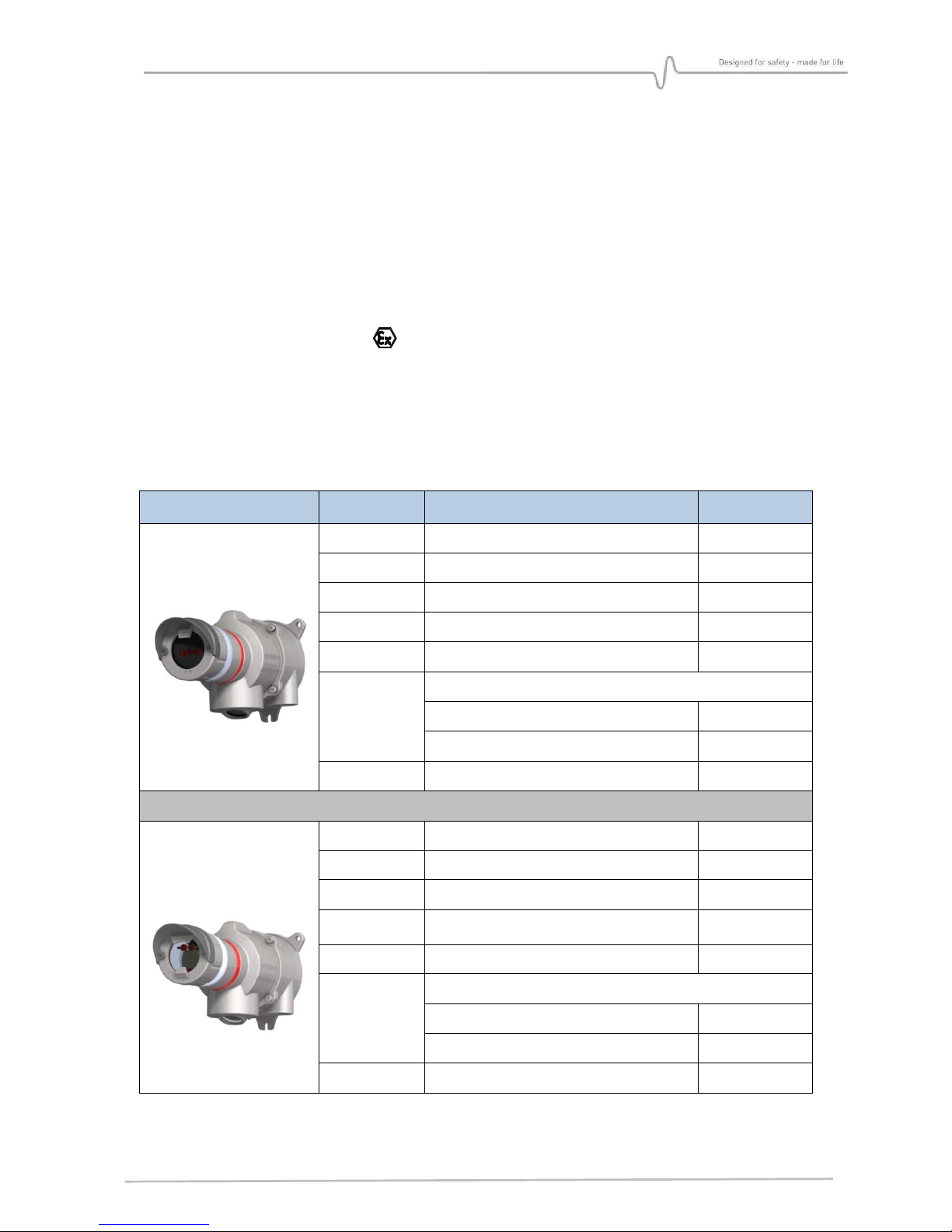
1.2. DF-TV7-T: multi-spectrum IR
The DF-TV7-T is a multi-spectrum flame detect r using three
individual infrared wavelengths. The use f three different IR
bands and a unique signal pr cessing alg rithm all ws
excellent flame detecti n perf rmances, while ffering a very
l w rate f false alarms.
The detect r can be supplied with
•A "standard range" sens r cartridge c vering m st
applicati ns
•A “high sensitivity" sens r cartridge f r special applicati ns where the maximum
sensitivity is required.
1.3. DF-TV7-V: combined UV and IR
Designed t c ver a large detecti n range while ensuring excellent immunity against false
alarms, the DF-TV7-V is the alternative when multi-spectrum IR cann t be used.
False alarms are minimized by the use f tw infrared wavelengths plus a fast acting UV
wavelength t c nfirm detecti n. This versi n is useful in difficult envir nmental c nditi ns,
such as c mbined rain and wind, rapid sunshine variati ns, h t s urces m dulati ns,
industrial lighting etc.
The DF-TV7-V is als c nfigurable f r special applicati ns,
where using just dual IR r just direct UV detecti n is
required.
The UV detect r can be sensitive t UV welding radiati n r
lightning, X rays and gamma rays.

MultiFlame DF-TV7 Page 8 / 56 NOSP16358-03 [04/2016]
1.4. Technical specifications
Each detect r is c nstructed as f ll ws:
•A wall-m unted supp rt secured by three screws and including cable gland (M20)
( pti nal). There are 2 standard entries and an pti nal ne.
•A stainless steel (316L) expl si n-pr f h using c ntaining:
•A set f tr picalized electr nic cards
•A display and infrared c mmunicati n electr nic card all wing the
c mmunicati n with the rem te c ntr l (TLU600)
•The sens r cartridge c ntains the flame detecti n circuitry. S , it is p ssible t
change the cartridge easily. The multispectrum IR detect r is als available in a high
sensitivity versi n.
•An IR c mmunicati n head is l cated bel w the detect r h using. It is used f r
c mmunicati n with the maintenance hand-held terminal (TLU).
•A metallic supp rt cable ( pti nal) c nnects the wall m unting supp rt and the
h using, making the maintenance easier.
Figure 1 : Detect r presentati n
(Overall dimensi n drawings, see Figure 2)

MultiFlame DF-TV7 Page 9 / 56 NOSP16358-03 [04/2016]
1.5. Detection Cartridge
Cartridges are expl si n pr f designed. They are c mm n t all MultiFlame line f pr ducts
in rder t reduce spares parts.
•DF-RV7-T and DF-RV7-V: Netw rk “Telecapt r” flame detect r line,
•DF-TV7-T and DF-TV7-V: “Telecapt r” flame detect r line.
Alarms inf rmati n is indicated by the flashing f a red LED in the c mmunicati n head and
f tw LEDs l cated in fr nt f the detecti n cartridge. Inf rmati n and detect r status is
als available via the rem te c ntr l TLU 600/610 display.
The cartridge must not be removed when the detector is powered.
1.6. Optical self-test function
Sens r cartridges have ne r m re self-test ptical lamps all wing detecti n integrity test.
This is a full ptical test where the signal fr m each test lamp is transmitted thr ugh the
sens r wind w and reflected back t the detecting elements via a p lished stainless steel
reflect r.
In additi n t this cyclic self-test, the test lamps can be used when a "flame simulati n test"
is initiated by the maintenance terminal. Further testing is n t required t c nfirm c rrect
perati n.
1.7. Wireless Configuration Tool
Inf rmati n and status f the detect r are available via the wireless c nfigurati n t l
TLU600/610.
C nfigurati n and tests are perf rmed using this wireless c nfigurati n t l (IrDA pr t c l).
This t l is c mm n f r all Simtr nics MultiFlame, MultiXpl and
MultiT x pr ducts.
The TLU600/610 pr vides access t devices which, therwise, w uld
require maj r l gistic perati ns f r maintenance r f r
c nfigurati n (calibrati n …).
F r m re details, please refer t the wireless c nfigurati n t l
perating manual.
S me versi ns are equipped with the HART c mmunicati n pr t c l, enabling
the use f all functi ns available with the TLU (see §7)
MultiFlame DF-TV7 Page 10 / 56 NOSP16358-03 [04/2016]
1.8. roduct Code
Pr duct c des are created fr m functi nal c des: DF-
ξ
V7-X#
σ
0-0
αβ
-0
ρ
-00
ε
-
µ
-
φ
-0
Detector type
ξ
V 7
XV
XT
σ
0
-0
α
β
-0
ρ
-00
ε
-
µ
-
φ
-0
T
**
Télécaptor
R
**
Network version
Families
*
V
*
Flame
Version
**
7
BT10 housing
Type
XV
UVIR2
XT
IR3
XW
UV
Detection range
σ
0
A0
Standard range
B0
Long range
Type
0
0
**
Not used
or flame
Variant
α
*
A
*
Aluminium
*
X
*
SS316
Interface
β
**
A
0
-
22mA protocol (fault signalling in 0
-
4mA range)
**
E
4
-
20 mA protocol (Common fault signal 2 mA)
**
H
4
–
20 mA / 0
-
22 mA configurable & HART protocol
**
C
4
–
20 mA / 0
-
22 mA configurable
**
L
LON
Cartridges
0
0
*
No cartridge
ornotspecified orflame
Semicond.Sensor type & special configurations
ρ
*
0
Not specified
orstandard
*
M
Special version MarED (TX
6
and TV
6 in type A only
)
*N
Special version with ALRM LED
not memorized (not in
compliance with EN 54-10) (flame version only)
*
R
With relay board for HW type D
*1
CustomizedEPR (special follow up, SP4M20)
(DM and DMi only)
Configuration
00
ε
000
Standard
00A
Absolutely no grease
00B Special version MarED (old code)
(TX6 and TV6 in typeA only)
00G
Hydrocentrifugon paint (nuclear applications)
00H
Special paint :
light grey
(10A03
according to
«
British standards 4800/5252
»)
Language
µ
0
Fr / GB
F
French
E
English
P
Portuguese
C
Chinese
Hardware version
φ
A
Type
63
B
Type 65
C
Type 67 (HART)
D
Type 69 (magnet)
Software version
0
0
Standa
rd

MultiFlame DF-TV7 Page 11 / 56 NOSP16358-03 [04/2016]
2. TECHNICAL FEATURES
GENERAL
Type Optical flame detect rs
DF-TV6-T Multi-spectrum IR Flame detect r
DF-TV7-V C mbined IR and UV detecti n.
Start-up time 15 secs
Self-test Aut matic peri dic test thr ugh the wind w
Calibrati n Fact ry set, n field recalibrati n
OUT UT SIGNAL
4-20mA l p signal Active type (s urce), max. l ad impedance 700Ω.
E-variant, "4-20mA" 4-20mA l p with a single fault level
- N rmal 4 mA
- Flame alarm 20 mA
- Fault r inhibiti n 2 mA
A-variant, "0-22mA" 4-20mA l p with multiple fault levels, suitable f r PLC’s
and m dern c ntr l systems.
- N rmal 4 mA
- Flame alarm 20 mA
- Inhibiti n 3.4 mA
- Optical self-test fault 2.6 mA
- HW/SW fault 2.0 mA
Relay utput 2 x c nfigurable relays max 1A / 30V, AC/DC
ELECTRICAL
P wer supply 24V DC (range 18 – 28 V DC versi ns DF-T#7)
(Range 18 – 30 V DC versi ns DF-R#7)
P wer c nsumpti n 70 mA n rmal; 155 mA during ptical self-test
C nnecti n 0.3 mm2 (22 AWG) - 1.5 mm2 (16 AWG)
ENVIRONMENTAL
Temperature (St rage) -40°C t +70°C
Temperature (Operati n) -40°C t +65°C
Pressure 1013 HPa ± 10%
Humidity 95% RH (n n c ndensable)
MultiFlame DF-TV7 Page 12 / 56 NOSP16358-03 [04/2016]
Pr tecti n IP66
RFI/EMI C mplies with EN 50130-4 (2011 AMD 2014)
ERFORMANCE
Eur pean EN 54-10/A1 (2005)
EX LOSION ROOF HOUSING
Material 316 L stainless steel
Weight 5.1 kg
ATEX/IECEx II 2 G / Ex d II C T6 Gb
-40°C < Ta < + 65°C
FONCTIONNAL SAFETY
SIL SIL certified acc rding IEC/EN 61508 parties 1 t 3 standard
Certificati n b dy : LCIE Bureau Véritas
DETECTOR FACTOR. DEFINITIONS VALUE
Multi IR
DF-TV7-T
MTBF
Mean Time Between Failure
191 500 h
λ
Failure rate per hour
0.52x10
-5
/h
SFF
Safety fraction failure (T1=6 h)
99.2%
PFD
Probability of failure on Demande
1.21x10
-6
PFH
Probability of failure / h (1oo1)
4.2x10
-8
MTTR
Mean Time To Repair
Fault on cartridge
16 min
Fault on Detector
26 min
SIL
compliance
HFT = 0 / G.Fixed / 30°C / type B
3
UVIR2
DF-TV7-V
MTBF
Mean Time Between Failure
162 000 h
λ
Failure rate per hour
0.62x10
-5
/h
SFF
Safety fraction failure
98.4%
PFD
Probability of failure on demand (T1=2.5
h)
1.45x10
-6
PFH
Probability of failure / h (1oo1)
9.8x10
-8
MTTR
Mean Time To Repair
Fault on cartridge
16 min
Fault on Detector
26 min
SIL
compliance
HFT = 0 / G.Fixed / 30°C / type B
2

MultiFlame DF-TV7 Page 13 / 56 NOSP16358-03 [04/2016]
DIMENSIONS
Figure 2 : Dimensi n drawings
MultiFlame DF-TV7 Page 14 / 56 NOSP16358-03 [04/2016]
3. ERFORMANCES
3.1. Sensitivity
3.1.1. Fire class
Classificati n acc rding t §5.5.3 –NF EN 54-10 (2006), (ethan l and n-heptane fires)
DF-TV7-XVA0 ET DF-TV7-XTA0
Sensitivity
Time delay
50%
75%
100%
Min
Class 2
Class 1
Class 1
Max (20 sec)
Class 2
Class 2
Class 1
DF-TV7-XTB0
Class 1 f r any c mbinati ns f sensitivity and time delay settings.
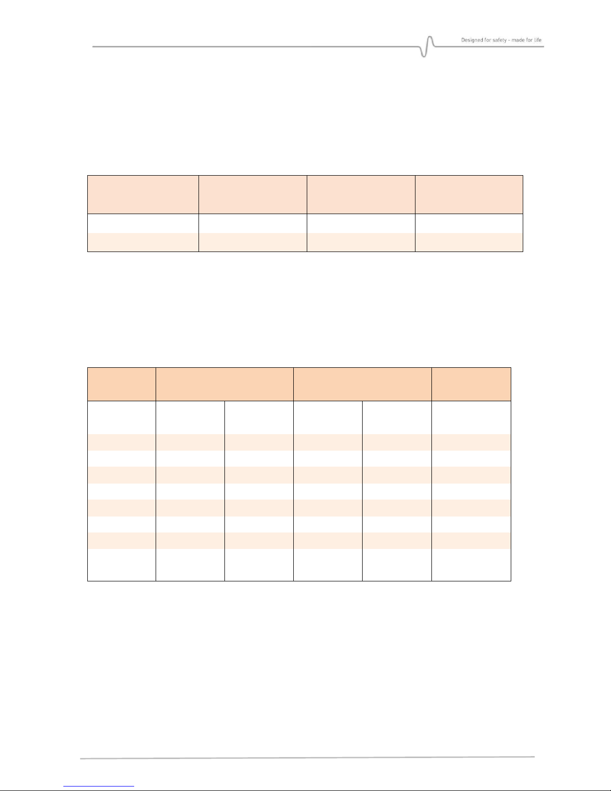
3.1.2. Fire range of detection
Detecti n range f r a standard 1 square f t (0.33 x 0.33m) fire except where stated.
XTB0
(IR
3
– L ng range)
XTA0
(IR
3
–Standard range)
XVA0
(UVIR²)
Sensitivity /
time delay
75 % / 5 sec
(Fact. Setting)
100 % / 5 sec
50 % / 5 sec
100% / 5 sec
(Fact. Setting)
100 % / 2 sec
(Fact. Setting)
Ethyl alc h l
**
37 m (122
ft.
)
50m (164
ft.
)
12 m (40
ft.
)
25m (82
ft.
)
25m (82 ft.)
Methan l
*
36
m (120
ft.
)
48 m (160
ft.
)
12m (40
ft.
)
30 m (100
ft.
)
19 m (62
ft.
)
Diesel
**
37 m (122
ft.
)
50 m (164
ft.
)
12 m (40
ft.
)
25m (82
ft.
)
30m
(100 ft.)
Gas line
**
49 m (161
ft.
)
65 m (213
ft.
)
16 m (52
ft.
)
32m (105
ft.
)
35m (115 ft.)
JP4 (2x2 ft²)
*
55 m (180
ft.
)
73 m (239
ft.
)
21 m (70
ft.
)
42 m (138
ft.
)
55 m
(180 ft)
N
-
heptane
*
65 m (215
ft.
)
80 m (265
ft.
)
27 m (90
ft.
)
54 m (177
ft.
)
45m
(147 ft)
*** Methane
45
m (1
47
ft.)
60 m (200 ft.)
15 m (49
ft)
30 m (100 ft.)
35m (115 ft.)
Pr pane
(10in.)*
6.4 m (252in.)
8.5 m (336 in.)
2.4 m (95 in.)
4.8 m (190in.)
4.8 m (190 in.)
(*) Tested acc rding t the FM 3260 standard
(**) Other measurements (
Italic:
calculated Extrap lati n)
(***) Measured n a 0.17x0.17 size fire with a plume height f ab ut 0.8 m
B ld = experimental measures, italic =extrap lati ns
MultiFlame DF-TV7 Page 15 / 56 NOSP16358-03 [04/2016]
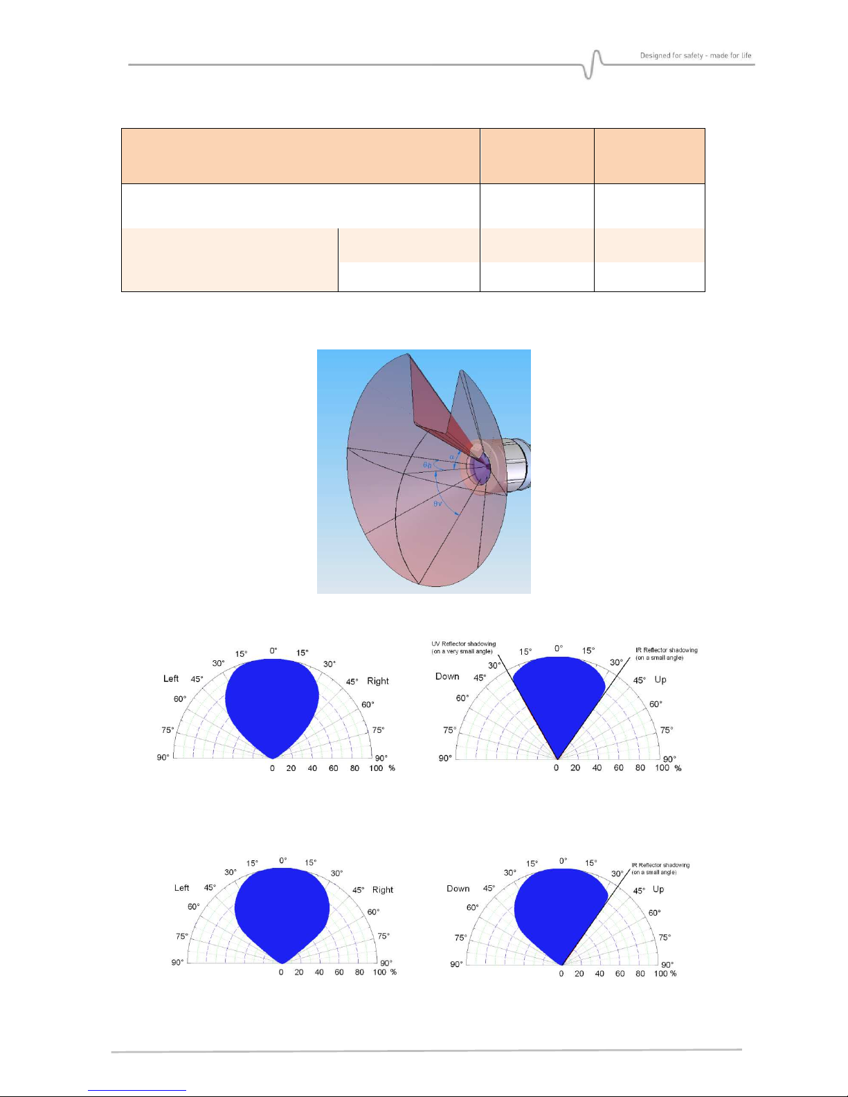
3.2. Field of View (Cone of Vision)
DF-TV7-XVA0
DF-TV7-XTA0
and
DF-TV7-XTB0
α
max
: Maximum angle as defined in standard EN 54-10
(2006) - § 5.4 30° 35°
Angle at 50% sensitivity
(in acc rdance with FM 3260
standard)
H riz ntal t tal 97° 104°
Vertical Up / D wn
20° / 35° 30° / 52°
The vertical viewing angle is limited by the self-test reflect rs n a thin s lid angle
DF-TV7-XVA0
DF-TV7-XTA0 AND DF-TV7-XTB0
Typical h riz ntal detecti n: Typical vertical detecti n:

MultiFlame DF-TV7 Page 16 / 56 NOSP16358-03 [04/2016]
3.3. False alarm immunity (FM 3260)
Distance
m (ft.)
XTB0 (IR3)
L ng range
XTA0 (IR3)
Standard
range
XVA0 (UVIR²)
M dulated /
Steady
75 % / 5 sec
(fact. setting)
100% / 5 sec
(fact. setting)
100 % / 2 sec
(fact. setting)
Arc welding, steady,
#7014, 3/16 in,
190A
3.6 / 3.6 (12/12) N False Alarm N False Alarm N false Alarm
7.6 / 7.6 (25/25)
1.5 kW heater 3.0 / 1.8 (10/6) N False Alarm N False Alarm N False Alarm
100 W incandescent
lamp 0.9 / 0.9 (3/3) N False Alarm N False Alarm N False Alarm
Tw 40 W
flu rescent lamps 0.9 / 0.9 (3/3) N False Alarm N False Alarm N False Alarm
100 W hal gen
lamp 2.4 / 2.4 (8/8) N False Alarm N False Alarm N False Alarm
MultiFlame DF-TV7 Page 17 / 56 NOSP16358-03 [04/2016]
4. INSTALLATION
The detector must be installed in accordance with its certification and with the
standards of the appropriate authority in the country concerned.
4.1. Location
The detect r sh uld be p siti ned ab ve the targeted danger z ne and at a distance
c rresp nding t the type f fire it have t detect.
Be aware f p tential radiati n s urces as these may trigger a false alarm. If p ssible, put
the detect r in clean z ne, sheltered fr m maj r vibrati ns. F r maximum effectiveness,
av id t exp se the head f sens r t alternati n f light and shade (passing vehicles, tree
branches…).
IR s urces (particularly if m dulated) like h t machinery, exhaust utlets, etc. may als de-
sensitize the detect r, masking the radiati n fr m a small fire.
F r detect rs using the UV wavelength:
Do not position the detector behind a glass window as this blocks UV radiation.
Locations where smoke, gas or vapours capable of absorbing UV radiation could
accumulate (e.g. ceilings) should be avoided as well.
Detect r fields f visi n may be verlapped, particularly if the devices are used in a v ting
c nfigurati n.
The detect r sh uld have a direct line- f-sight t the p tential fire s urce. Partial
bstructi n may reduce detecti n rate.
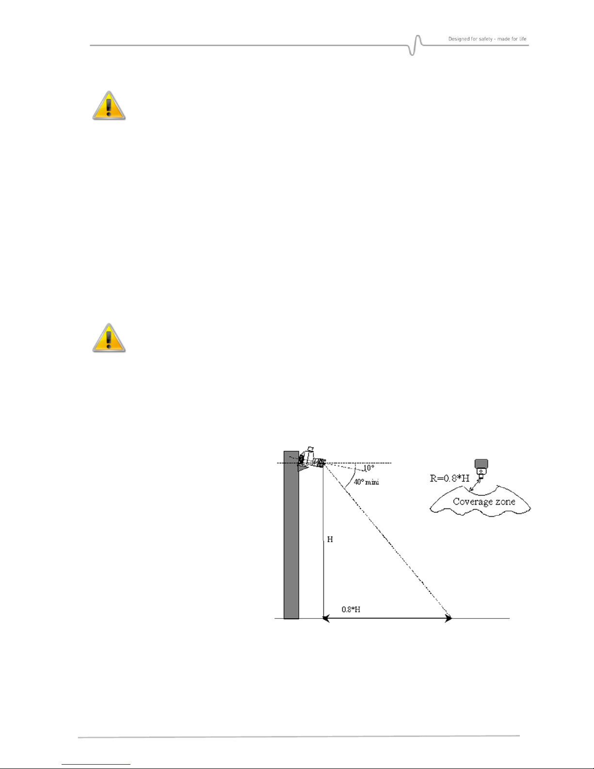
F r an inclinati n f 10°, there is a
semicircle blind z ne, directly bel w
the detect r, with a radius f 0.8 times
the detect r height. With this angle, the
ptical axis “t uch” the gr und at a
distance f 5.7 times the height.

MultiFlame DF-TV7 Page 18 / 56 NOSP16358-03 [04/2016]
4.2. Mounting
Use the tw 7 mm diameter h les and the half sl tted h le t secure the supp rt.
It is highly rec mmended t install the supp rt with cable-gland d wnward in rder t av id
water infiltrati ns. In case f h riz ntal p siti n, it is advised t make ne r tw l ps with
the cable at the entry f the cable-gland.
Figure 3 : Drilling dimensi ns f r supp rt fixing.
4.2.1. Multi-position support
Multi-position wall mount bracket AS054
4.2.1.1.
In this c nfigurati n, the supp rt is
made by tw brackets c nnected each
ther by tw CHC M6 screws.
The main bracket is fixed n the wall,
all wing the detect r t be in
h riz ntal p siti n, perpendicular t
the wall. The vertical angle is adjusted
using ne f the 4 t p h les f bracket.
Start by fixing the base supp rt. The adjustment and
terminati n f cables are perf rmed int the base nly.
This limits the exp sure f the electr nic c mp nents in
the h using t a minimum.

MultiFlame DF-TV7 Page 19 / 56 NOSP16358-03 [04/2016]
Ball pivot bracket – AS048
4.2.1.2.
The detect r is supp rted by a c mpletely adjustable supp rt. The assembly f the bracket
with the device is d ne by a CHC M14 x 24 screw. These ne is used t set the lateral
rientati n.
4 fixati ns (M8) fix the supp rt t the wall r n a tube (2 inch r 2.5 inch). Tighten tw CHC
M14 screws all ws the vertical rientati n.
The whole weigh approximately 7 Kg.
4.2.2. Detector assembly
Check the presence f the O-ring n expl si n pr f seal, make sure that it is c rrectly
greased and has n visible damage.
Plug c nnect rs t the base, as described in paragraph “Electric c nnecti n”.
Fit the main h using n the base, placing the cable excess in the base. Put in place and
tighten the f ur M5 screws with their gr wer rings.
It is p ssible t set up a suspensi n cable (n t supplied) between the base and the h using
(at the l wer part) with the tw threaded h les (M4 x 6).

MultiFlame DF-TV7 Page 20 / 56 NOSP16358-03 [04/2016]
4.2.3. Sunshade / bad weather protection
A sunshade / weather pr tecti n (AS056-450) in light and resistant material (UV resistant) is
available. M unted ab ve the detect r, it gives an additi nal pr tecti n against sun and bad
weather.
4.2.4. Detector cartridge visor
The detect r is fitted with a sh rt vis r f r pr tecti n f the ptical
detect r wind w (standard). There are tw additi nal m dels available if
further pr tecti n is required.
AS040: L ng vis r with n h riz ntal c verage reducti n
AS041: L ng vis r with side blinker.
4.2.5. Cable‘s inputs (as an option)
Connection cables must pass through a cable gland (Explosion roof certified)
F r installati n details, refer t the instructi ns pr vided by the manufacturer f the cable
gland used.
The unassigned cable glands entries must be blanked with explosion proof
certified plugs (M20).They are glued with Loctite (tubétanche 577) or equivalent
compound. If a plug is moved or removed, it must be glued again with Loctite or an
equivalent.
This manual suits for next models
1
Table of contents


