GEZE GC 402 WVS User manual

1
GEZE
GC 401 RS
GC 402 WVS
DE Wind- und Regensensor Set
GB Wind- and Rain Sensor Set
DE Montageanleitung
GB Installation instructions

GC 401 RS , GC 402 WVS
DE 2
Symbole und Darstellungsmittel
Symbole und Darstellungsmittel1
Warnhinweise
In dieser Anleitung werden Warnhinweise verwendet, um Sie vor Sach- und Personenschäden zu warnen.
Lesen und beachten Sie diese Warnhinweise immer.
X
Befolgen Sie alle Maßnahmen, die mit dem Warnsymbol und Warnwort gekennzeichnet sind.
X
Warnsymbol Warnwort Bedeutung
GEFAHR Gefahren für Personen.
Nichtbeachtung führt zu Tod oder schweren Verletzungen.
– VORSICHT Informationen zur Vermeidung von Sachschäden, zum Verständnis oder zum Optimie-
ren der Arbeitsabläufe.
Weitere Symbole und Darstellungsmittel
Um die korrekte Bedienung zu verdeutlichen, sind wichtige Informationen und technische Hinweise besonders
herausgestellt.
Symbol Bedeutung
bedeutet „Wichtiger Hinweis“
bedeutet „Zusätzliche Information“
XSymbol für eine Handlung: Hier müssen Sie etwas tun.
Halten Sie bei mehreren Handlungsschritten die Reihenfolge ein.
X
Produkthaftung2
Gemäß der im Produkthaftungsgesetz denierten Haftung des Herstellers für seine Produkte sind die in dieser
Broschüre enthaltenen Informationen zu beachten. Die Nichtbeachtung entbindet den Hersteller von seiner
Haftungspicht.
Sicherheitshinweise3
Diese Anleitung richtet sich an ausgebildetes Fachpersonal. Grundlegende Arbeitsschritte werden nicht erläutert.à
Evtl. Gewährleistungsansprüche setzen fachgerechte Montage, Installation und Wartung nach den Angabenà
des Herstellers voraus.
Nur GEZE Originalteile für Reparaturarbeiten verwenden.à
Eigenmächtige Veränderungen an der Anlage schließen eine Haftung von GEZE für daraus resultierendeà
Schäden aus.
GEFAHR Die Gerätemontage und deren Anschluss darf nur durch eine Fachrma nach den
Vorschriften von VDE und des örtlichen EVUs vorgenommen werden.
Metallteile müssen wegen Blitzschutz entsprechend den rechtlichen Bestimmun-
gen und Normen geerdet werden.
Produktbeschreibung4
Anwendung4.1
Automatische Melder zum wetterabhängigen Önen und Schließen von elektromotorisch betriebenen Gebäu-
deönungen im Lüftungsbetrieb.

GC 401 RS , GC 402 WVS
DE 3
Produktbeschreibung
Lieferumfang4.2
Windgeschwindigkeits- und Regensensor Set (Mat.-Nr. 140229)
Regensensor (24 V DC/AC) mit Gerätekonsole GC 401 RS1
Windgeschwindigkeits-Sensor GC 402 WVS2
Klemmring3
Konsole (Aluminium) für Wand- oder Mastmontage4
Produktmerkmale4.3
Regensensor Windgeschwindigkeits-Sensor
Anschluss Anschluss
Messprinzip: Leitwertmessungà
Sensor und Auswertung in einem Gerätà
Optische Anzeige des Schaltzustandesà
Hohe Sicherheit durch Vergusstechnikà
Vergoldete, korrosionsbeständige Sensor-Elektrodenà
Beheizte Messächeà
Messprinzip: Impulsmessungà
3 Windschalen witterungsbeständigen Polyamidà
Wartungsfreie Kugellagerung durch Dauerschmierungà
Technische Daten4.4
Artikel Regensensor Windgeschwindigkeits-Sensor
Mat.-Nr. 140226 140227
Versorgungsspannung 24 V DC +/- 20% 24 V DC +/- 20%
Leistungsaufnahme W max. 6 -
Kontakt 1 x Wechselkontakt, potentialfrei -
Kontaktbelastung max. 42 V, 5 A -
Gehäuse (PC+ABS)-Blends Polyamid (PA66)
Schutzart IP 65 33
Gehäusemaße (B x H x T) mm ca. 100 x 90 x 40 ca. 250 x 250 x 80
Anschlusskabel PVC PVC
Kabellänge m ca. 4,0 (5 x 0,75 mm2) ca. 3,0 (2 x 0,5 mm²)
Umgebungstemperaturbereich °C -20....+40 -20....+40
Abschaltverzögerung min ca. 5,0 Abhängig von Einstellung in der
Steuerung
Umschaltverzögerung s ca. 1,0
Anzeige Schaltzustand ohne
Ausstattung Beheizte Messächeà
Sensor, vergoldetà
Impulsgeneratorà
wartungsfreies Lagerà
Lieferumfang mit Wandkonsole mit Klemmring
Lieferumfang Set zusätzlich: Konsole (Aluminium) für Wand- oder Mastmontage

GC 401 RS , GC 402 WVS
DE 4
Montage
Montage5
Die Sensoren sind an einer dem Wetter zugewandten Gebäudeseite zu montieren. Umliegende Gebäudeteileà
sowie elektrische Geräte dürfen deren Funktion nicht beeinträchtigen.
Die Konsole muss auch bei extremen Wetterverhältnissen (Sturm) sicheren Halt gewährleisten.à
Metallteile müssen wegen Blitzschutz entsprechend den rechtlichen Bestimmungen und Normen geerdetà
werden.
Montage des Windsensors (ohne Regensensor) auf Mast ø 20 - 35 mm5.1
Der Schaltpunkt für den Windgeschwindigkeits-Sensor muss den örtlichen Gegebenheiten angepasst werden.
Werkseitig ist die kleinste Windgeschwindigkeit eingestellt.
Bei der Montage der Windschalen, auf Nut undà
Feder achten.
Unbedingt darauf achten, dass beim Einschie-à
ben der Windschalen der Nabenstern gehalten
wird. Wird das Gehäuserohr (Alu) gehalten,
können Beschädigungen im Lager entstehen.
Windschale soweit in die Führung einschieben
X
bis beide Halteklammern einrasten.
Mutter (4) auf Schraube (3) drehen und in
X
Klemmring (1) min.15 mm einschrauben.
Gehäuserohr (5) in Klemmring (1) bis Anschlag
X
stecken und Klemmschrauben (2) anziehen bis
Windgeschwindigkeits-Sensor fest ist.
Gehäuserohr (5) mit montiertem Klemmring (1)
X
auf Mast stecken, mit Schraube (3) an Mast klem-
men und mit Mutter (4) kontern.
Klemmring1
Klemmschrauben2
Schraube3
Mutter4
Gehäuserohr5
Mast Ø 20 mm
Mast Ø 35 mm
2
5
1
4
3

GC 401 RS , GC 402 WVS
DE 5
Wartung, Pege, Reparatur
Montage von Wind- und Regensensor an Wand-/ Mastkonsole5.2
Kabel von Wind-/Regensensor (10) durch
X
das Rohr des Wand-/Masthalters (7)
führen.
Schraube (3) in Klemmring (1) min. 15 mm
X
einschrauben.
ACHTUNG
X: Rohr (7) vorsichtig bis zum
Anschlag in den Klemmring (1) schieben
und darauf achten, dass das Kabel in der
Kabeleinführung des Klemmrings liegt
(siehe Ansicht Z), anschließend beide
Schrauben (2) anziehen.
Schraube (3) herausdrehen.
X
Den Regensensor mit Halterung (8) mit
X
beiden Schrauben (6) am Klemmring (1)
festschrauben
Befestigungsschraube der6
Konsole von Regensensor, dient
auch als Anschlag von Wand-
konsole und Windgeschwindig-
keits-Sensor.
Wand- oder Mastkonsole7
Regensensor mit Halterung8
Windgeschwindigkeits-Sensor9
Kabel von Wind-/Regensensor10
Halterung von Regensensor11
Kabeleinführung in Klemmring12
Ansicht Z
Abnahmeprüfung5.3
Nach dem betriebsfertigen Einbau der Anlage ist am Verwendungsort deren einwandfreie Funktion und vor-
schriftsmäßige Installation durch eine Abnahmeprüfung festzustellen. Abnahmeprüfung durch autorisiertes
Fachpersonal.
Wartung, Pege, Reparatur6
Um eine zuverlässige Funktion auf Dauer sicherzustellen, ist es unerlässlich, die Anlage von einer autorisierten
Fachrma reinigen und mindestens jährlich warten zu lassen.
Die Einbaurma muss den Betreiber der Anlage auf diesen Teil der Montageanleitung aufmerksam machen, und
diese sowie die Benutzerinformation dem Betreiber aushändigen.

GC 401 RS , GC 402 WVS
GB 2
Key to symbols
Key to symbols1
Warning
In these instructions, warnings are used to warn against material damage and injuries.
Always read and observe these warnings.
X
Follow all instructions marked with the warning symbol and the word WARNING.
X
Warning
symbol
Warning Meaning
DANGER Danger for people.
Non-observance can result in death or serious injuries.
– CAUTION Information to prevent damage to property and to understand and optimise workow.
Further symbols used in these instructions
Important information and technical notes are emphasised to illustrate the correct operation.
Symbol Meaning
means “Important note“
means “Additional information”
XSymbol for a user action. Here you have to take an action.
Observe the sequence if there are several action steps.
X
Product liability2
According to the denition of manufacturer‘s liability for his products in the Product Liability Act, the informati-
on contained in this brochure are to be followed. Ignoring this information absolves the manufacturer from his
liability.
Safety instructions3
Installation, commissioning and repairs must be performed by a specialist.à
Basic techniques are not explained.
Warrenty claims require professional installation and service according to the guidelines of the manufacturer.à
Use only GEZE original parts for repair work.à
Unauthorised modications of the system excludes GEZE from the liability for any resulting damage.à
DANGER All electrial connections should be made by a properly electricain and connected in
accordance wit
h the appropriate standards of the country of installation.
Ground metal parts for protection against lightning according to the national safety
regulations.
Product description4
Application4.1
Automatic detectors for electromotive opening and closing of building vents depending on weather in ventilati-
on mode.

GC 401 RS , GC 402 WVS
GB 3
Product description
Scope of delivery4.2
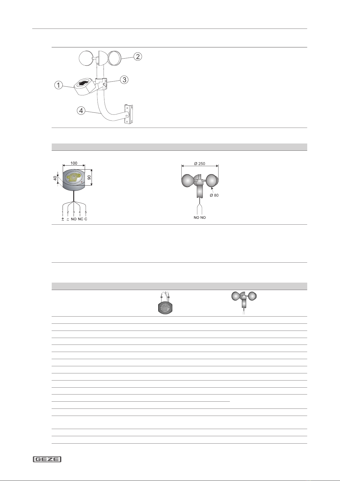
Wind speed and Rain Sensor Set (Mat.-No.: 140229)
Rain sensor (24 V DC/AC) with equipment bracket GC 401 RS1
Wind speed sensor GC 402 WVS2
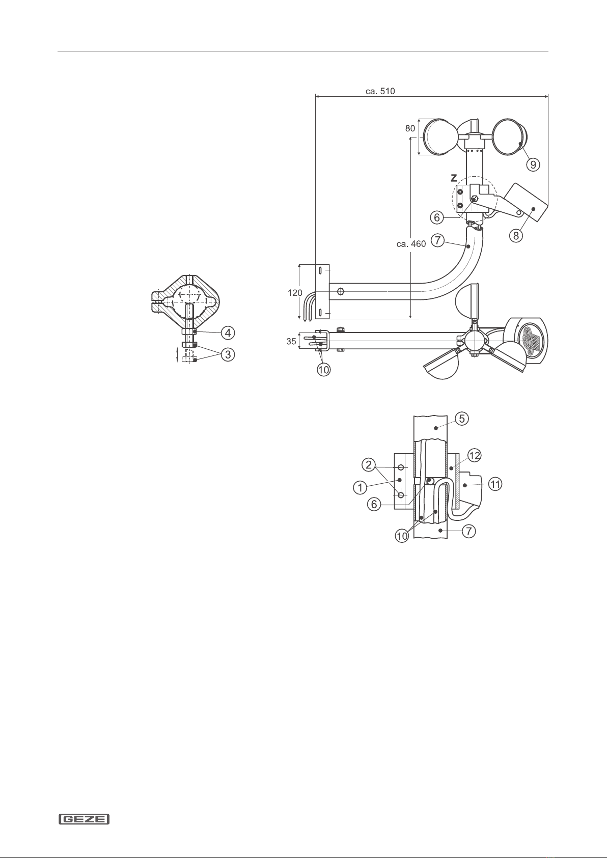
Clamping Ring3
Bracket (aluminium) for pole or wall mounting4
Special Features4.3
Rain sensor Wind speed sensor
Connection Connection
Function principle: conductivity measurementà
Sensor and controller in the same housingà
Optical display for switching statusà
High security through potting technologyà
Corrosion resistant through gold-plated sensorà
Heated measuring surfaceà
Function principle : pulse measurementà
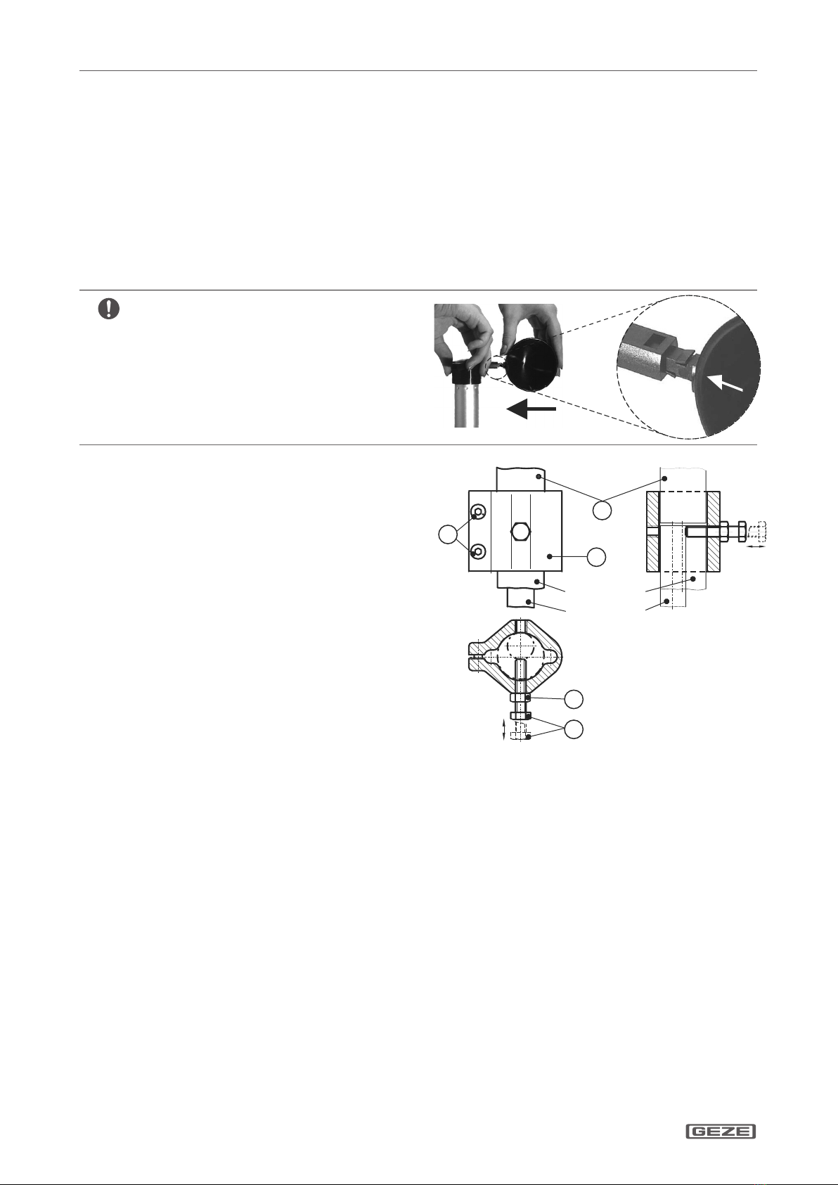
3 wind shells made of weather-resistant polyamideà
Maintenance-free ball bearing by lifetime lubricationà
Technical Data4.4
Item Rain sensor Wind speed sensor
Mat.-No. 140226 140227
Power supply 24 V DC +/- 20% 24 V DC +/- 20%
Power consumption W max. 6 -
Contact 1 x changeover, potential-free -
Contact rating max. 42 V, 5 A -
Housing (PC+ABS)-Blends Polyamide (PA66)
Protection class IP 65 33
Housing dimensions (B x H x T) mm ca. 100 x 90 x 40 ca. 250 x 250 x 80
Connection cable PVC PVC
Cable length m ca. 4,0 (5 x 0,75 mm2) ca. 3,0 (2 x 0,5 mm²)
Ambient temperature range °C -20....+40 -20....+40
Turn-o delay min ca. 5,0 depends on the settings of the
control unit
Switch-over delay s ca. 1,0
Display Switching status without
Special feature Heated measuring surfaceà
Sensor, gold-platedà
pulse generatorà
maint.-free bearingà
Scope of delivery with bracket with clamping ring
Delivery set in addition: Bracket (aluminium) for pole or wall mounting

GC 401 RS , GC 402 WVS
GB 4
Mounting
Mounting5
The sensors have to be mounted on the weather side of building. Surrounding buildings and electrical equip-à
ment must not impair their function.
The mounting bracket has to be xed for extremely weather conditions.à
Ground metal parts for protection against lightning according to the national safety regulations.à
Assembly of wind speed sensor (without rain sensor) on 20 - 35 mm pole5.1
Adjust the wind speed setting for the specic situation of building (smallest value pre-set by the factory).
Pay attention to groove and spring when as-à
sembly the wind shells.
It is very important to hold the hub-star duringà
xing the wind shells. Don´t hold the alumini-
um tube to avoid damages at the bearing!
Click the shells into guidance, until engageà
both holding clamps.
Turn the nut (4) on screw (3) and screw both min.
X
15 mm into the clamp ring (1).
Push the tube (5) into clamp ring (1) until limit
X
stop, then tighten clamp screws (2) until the wind
shells xed
Put tube (5) with mounted clamp ring (1) on pole.
X
Then x it with screw (3) on pole and counter the
locknut (4).
Clamp ring1
Clamp screws2
Screw3
Locknut4
T5 ube
Mast Ø 20 mm
Mast Ø 35 mm
2
5
1
4
3

GC 401 RS , GC 402 WVS
GB 5
Maintenance, servicing, repairs
Pole and wall mounting of wind speed and rain sensor5.2
Lead the cables (10) of wind and rain
X
sensor by the tube (7) of bracket
Turn the screw (3) min. 15 mm into clamp
X
ring (1).
NOTE
X: Push carefully tube (7) into clamp
ring (1) until limit stop. The cable must be
only xed in the cable input of the clamp
ring (compare view Z). Then x both
screws (2).
Turn screw (3) o.
X
Then x holding bracket of rain sensor (8)
X
with both screws (6) at clamp ring (1).
The bracket screw of rain sensor6
is also used as limit stop of wall
bracket and wind speed sensor.
Bracket for pole or wall mounting7
Rain sensor with holding bracket8
Wind speed sensor9
Trailing leads of wind speed &10
rain sensor
Holding bracket for rain sensor11
Cable input for clamp ring12
Ansicht Z
Testing for acceptance5.3
An acceptance test must be carried out in order to ascertain the correct function and installation according to
the regulations once the installation has been completed on site. Acceptance test to be performed by authorised
personnel.
Maintenance, servicing, repairs6
The wind and rain sensor set should be inspected at regular intervals, at least annually. Keep sensors and bra-
ckets clean for faultless operation.
The installing company must alert the operator of the system to this part of the mounting instructions and hand
it over to the operator together with the user information.

GC 401 RS , GC 402 WVS
Notizen / Notes:


Germany
GEZE Sonderkonstruktionen GmbH
Planken 1
97944 Boxberg-Schweigern
Tel. +49 (0) 7930-9294-0
Fax +49 (0) 7930-9294-10
E-Mail: [email protected]
Germany
GEZE GmbH
Niederlassung Nord/Ost
Bühringstraße 8
13086 Berlin (Weissensee)
Tel. +49 (0) 30-47 89 90-0
Fax +49 (0) 30-47 89 90-17
E-Mail: [email protected]
Germany
GEZE GmbH
Niederlassung West
Nordsternstraße 65
45329 Essen
Tel. +49 (0) 201-83082-0
Fax +49 (0) 201-83082-20
E-Mail: [email protected]
Germany
GEZE GmbH
Niederlassung Mitte
Adenauerallee 2
61440 Oberursel (b. Frankfurt)
Tel. +49 (0) 6171-63610-0
Fax +49 (0) 6171-63610-1
E-Mail: frankfurt[email protected]
Germany
GEZE GmbH
Niederlassung Süd
Breitwiesenstraße 8
71229 Leonberg
Tel. +49 (0) 7152-203-594
Fax +49 (0) 7152-203-438
E-Mail: [email protected]
Germany
GEZE Service GmbH
Reinhold-Vöster-Straße 25
71229 Leonberg
Tel. +49 (0) 7152-9233-0
Fax +49 (0) 7152-9233-60
E-Mail: service-info.de@geze.com
Germany
GEZE Service GmbH
Niederlassung Berlin
Bühringstraße 8
13086 Berlin (Weissensee)
Tel. +49 (0) 30-470217-30
Fax +49 (0) 30-470217-33
E-Mail: service-info.de@geze.com
Austria
GEZE Austria GmbH
Wiener Bundesstrasse 85
5300 Hallwang b. Salzburg
Tel. +43-(0)662-663142
Fax +43-(0)662-663142-15
E-Mail: austria.at@geze.com
Baltic States
GEZE GmbH Baltic States oce
Dzelzavas iela 120 S
1021 Riga
Tel. +371 (0) 67 89 60 35
Fax +371 (0) 67 89 60 36
E-Mail: oce-latvia@geze.com
Benelux
GEZE Benelux B.V.
Leemkuil 1
Industrieterrein Kapelbeemd
5626 EA Eindhoven
Tel. +31-(0)40-26290-80
Fax +31-(0)40-26 290-85
E-Mail: benelux.nl@geze.com
Bulgaria
GEZE Bulgaria - Trade
Representative Oce
61 Pirinski Prohod, entrance „B“,
4th oor, oce 5,
1680 Soa
Tel. +359 (0) 24 70 43 73
Fax +359 (0) 24 70 62 62
E-Mail: oce-bulgaria@geze.com
China
GEZE Industries (Tianjin) Co., Ltd.
Shuangchenzhong Road
Beichen Economic Development
Area (BEDA)
Tianjin 300400, P.R. China
Tel. +86(0)22-26973995-0
Fax +86(0)22-26972702
E-Mail: Sales-info@geze.com.cn
China
GEZE Industries (Tianjin) Co., Ltd.
Branch Oce Shanghai
Unit 25N, Cross Region Plaza
No. 899, Ling Ling Road,
XuHui District
200030 Shanghai, P.R. China
Tel. +86 (0)21-523 40 960
Fax +86 (0)21-644 72 007
E-Mail: chinasal[email protected].cn
China
GEZE Industries (Tianjin) Co., Ltd.
Branch Oce Guangzhou
Room 17C3
Everbright Bank Building, No.689
Tian He Bei Road
510630 Guangzhou, P.R. China
Tel. +86(0)20-38731842
Fax +86(0)20-38731834
E-Mail: chinasal[email protected].cn
China
GEZE Industries (Tianjin) Co., Ltd.
Branch Oce Beijing
Room 1001, Tower D
Sanlitun SOHO
No. 8, Gongti North Road,
Chaoyang District,
100027 Beijing, P.R.China
Tel. +86-(0)10-5935 9300
Fax +86-(0)10-5935 9322
E-Mail: chinasal[email protected].cn
China
GEZE Industries (Tianjin) Co., Ltd.
Branch Oce Singapore
21, Bukit Batok Crescent,
No. 23-75, Wcega Tower,
Singapore 658065
Tel. +65-6846 1338
Fax +65-6846 9353
E-Mail: gezesea@geze.com.sg
France
GEZE France S.A.R.L.
ZAC de l’Orme Rond
RN 19
77170 Servon
Tel. +33-(0)1-606260-70
Fax +33-(0)1-606260-71
E-Mail: france.fr@geze.com
Hungary
GEZE Hungary Kft.
Bartók Béla út 105-113.
Budapest
H-1115
Tel. +36 (1) 481 4670
Fax +36 (1) 481 4671
E-Mail: oce-hungar[email protected]
Iberia
GEZE Iberia S.R.L.
Pol. Ind. El Pla
C/Comerc, 2-22, Nave 12
08980 Sant Feliu de Llobregat
(Barcelona)
Tel. +34 9-02 19 40 36
Fax +34 9-02 19 40 35
E-Mail: info@geze.es
India
GEZE India Private Ltd.
MF2 & 3, Guindy Industrial Estate
Ekkattuthangal
Chennai - 600 097
Tamilnadu
Tel. +91 (0) 44 30 61 69 00
Fax +91 (0) 44 30 61 69 01
E-Mail: oce-in[email protected]
Italy
GEZE Italia Srl
Via Giotto, 4
20040 Cambiago (MI)
Tel. +3902950695-11
Fax +3902950695-33
E-Mail: italia.it@geze.com
Italy
GEZE Engineering Roma Srl
Via Lucrezia Romana, 91
00178 Roma
Tel. +3906-7265311
Fax +3906-72653136
E-Mail: roma@geze.biz
Kazakhstan
GEZE Central Asia
050061, Almaty, Kasakhstan
Rayimbek ave. 348, A, oce 310
Tel. +7 (0) 72 72 44 78 03
Fax +7 (0) 72 72 44 78 03
E-Mail: oce-kazakhstan@geze.com
Poland
GEZE Polska Sp.z o.o.
ul. Annopol 21
03-236 Warszawa
Tel. +48 (0)22 440 4 440
Fax +48 (0)22 440 4 400
E-Mail: [email protected]
Romania
GEZE Romania S.R.L.
IRIDE Business Park
Building nr. 10, level 2
Str. Dimitrie Pompei nr. 9–9a
RO-020335 Bucharest, sector 2
Tel. +40 (0) 316 201 257
Fax +40 (0) 316 201 258
E-Mail: oce-ro[email protected]
Russian Federation
GEZE GmbH Representative
Oce Russia
Kolodesnij pereulok3, str. 25
Oce Nr. 5201-5203
107076 Moskau
Tel. +7 (0) 49 55 89 90 52
Fax +7 (0) 49 55 89 90 51
E-Mail: oce-r[email protected]
Scandinavia
GEZE Scandinavia AB
Mallslingan 10
Box 7060
18711 Täby, Sweden
Tel. +46(0)8-7323-400
Fax +46(0)8-7323-499
E-Mail: [email protected]
Scandinavia
GEZE Norway
Industriveien 34 B
2072 Dal
Tel. +47(0)639-57200
Fax +47(0)639-57173
E-Mail: [email protected]
Scandinavia
GEZE Finland
Postbox 20
15871 Hollola
Tel. +358(0)10-4005100
Fax +358(0)10-4005120
E-Mail: nland.se@geze.com
Scandinavia
GEZE Denmark
Mårkærvej 13 J-K
2630 Taastrup
Tel. +45(0)46-323324
Fax +45(0)46-323326
E-Mail: danmark.se@geze.com
South Africa
DCLSA Distributors (Pty.) Ltd.
118 Richards Drive, Midrand,
Halfway House Ext. 111
P.O. Box 7934
Midrand 1685
Tel. +27(0)113158286
Fax +27(0)113158261
E-Mail: info@dclsa.co.za
Switzerland
GEZE Schweiz AG
Bodenackerstrasse 79
4657 Dulliken
Tel. +41-(0)62-2855400
Fax +41-(0)62-2855401
E-Mail: schweiz.ch@geze.com
Turkey
GEZE GmbH Türkiye - İstanbul
İrtibat Bürosu
Ataşehir Bulvarı, Ata 2/3
Plaza Kat: 9 D: 84 Ataşehir
Kadıköy / İstanbul
Tel. + 90 (0) 21 64 55 43 15
Fax + 90 (0) 21 64 55 82 15
E-Mail: o[email protected]
Ukraine
Repräsentanz GEZE Ukraine TOV
ul. Viskoznaya, 17, building 93-B,
oce 12
02094 Kiev
Tel. +38 (0) 44 501 22 25
Fax +38 (0) 44 499 77 25
E-Mail: oce-ukraine@geze.com
United Arab Emirates/GCC
GEZE Middle East
P.O. Box 17903
Jebel Ali Free Zone
Dubai
Tel. +971(0)4-8833112
Fax +971(0)4-8833240
E-Mail: geze@emirates.net.ae
United Kingdom
GEZE UK Ltd.
Blenheim Way
Fradley Park
Licheld
Staordshire WS13 8SY
Tel. +44(0)1543443000
Fax +44(0)1543443001
E-Mail: info.uk@geze.com
GEZE GmbH
P.O.Box 1363
Reinhold-Vöster-Straße 21–29
71229 Leonberg
Germany
Tel.: 0049 7152 203-0
Fax: 0049 7152 203-310
www.geze.com
143015-00
This manual suits for next models
1
Table of contents
Languages:
Other GEZE Accessories manuals
Popular Accessories manuals by other brands

Honeywell Home
Honeywell Home RDWL917AX2000 Installation and operation guide

Starizona
Starizona MicroTouch instructions

GE Lighting
GE Lighting CIR-15-360-D-T installation instructions

TankScan
TankScan TSU1000M Setup instructions

Klark Teknik
Klark Teknik DN32-LIVE quick start guide

Yale
Yale HSA6010 quick start guide