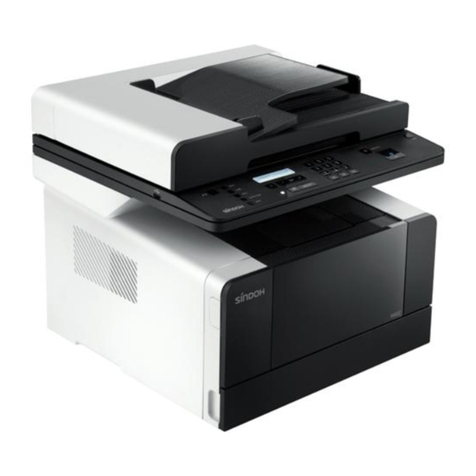
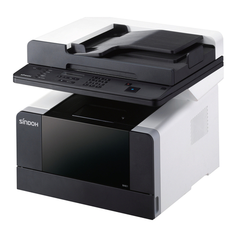
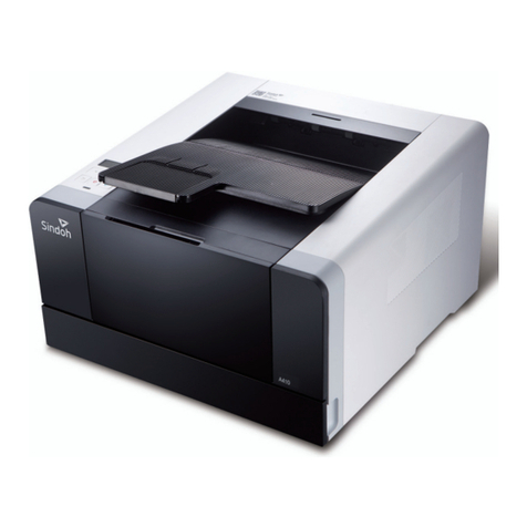
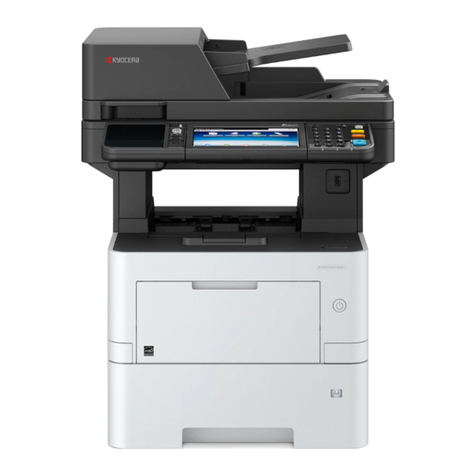
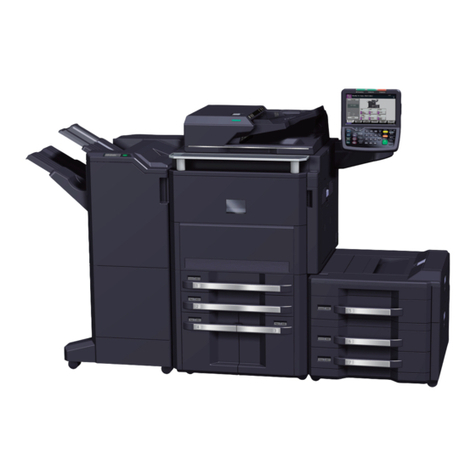
Sindoh M611 User manual

FIELD SERVICE MANUAL
M611 / M616 / M612 / M617
CS
2014-6-13
CE
Confid
ential

M611/616/612/617 MFP
FIELD SERVICE MANUAL
Machine Spec........................................................................................................................ 1
Base Unit......................................................................................................................... 1
500 sheets Option........................................................................................................... 3
Paper Tray Unit........................................................................................................ 3
Installation............................................................................................................................. 4
Installation Condition....................................................................................................... 4
Environment............................................................................................................. 4
Installation....................................................................................................................... 5
Unpacking and Check the Enclosure ...................................................................... 5
Optional Tray............................................................................................................ 6
Image Cartridge....................................................................................................... 7
Maintenance........................................................................................................................ 10
PM (Preventive Maintenance)....................................................................................... 10
Customer Changeable Items................................................................................. 10
Other Maintenance Items ...................................................................................... 10
Detailed Description............................................................................................................11
IMAGE PROCESS.........................................................................................................11
Electric Charge .......................................................................................................11
Laser Exposure.......................................................................................................11
Development.......................................................................................................... 12
Transfer.................................................................................................................. 12
Cleaning................................................................................................................. 13
MFP Overview............................................................................................................... 14
MFP Configuration................................................................................................. 14
Paper Path............................................................................................................. 16
Electrical Configuration Element............................................................................ 17

Driver Layout.......................................................................................................... 19
Main Driver Gear Unit............................................................................................ 19
Laser Unit...................................................................................................................... 22
Config and Optical Path......................................................................................... 22
LSU................................................................................................................................ 23
Image Cartridge........................................................................................................... 24
Overview............................................................................................................... 24
Components of Drum Cartridge............................................................................. 25
Components of Toner Cartridge............................................................................. 26
Driving Drum Cartridge.......................................................................................... 26
Driving Toner Cartridge ..................................................................................... 27
Voltage Supply to Drum Cartridge......................................................................... 27
Voltage Supply to Toner Cartridge......................................................................... 28
Replacement of Toner Cartridge and Drum Unit................................................... 28
Paper Feeding ............................................................................................................. 29
Overview............................................................................................................... 29
Paper Tray Layout and Mechanism .................................................................. 29
Pickup Unit Layout and Mechanism .................................................................. 30
Paper Tray Open / Close Mechanism ............................................................... 31
Paper Feed / Transport Mechanism..................................................................... 32
MPT(Multi-purpose Tray)....................................................................................... 38
Components Layout in Duplex Unit .................................................................. 41
Driving Duplex Unit............................................................................................. 42
Register Unit ........................................................................................................ 44
Fusing Images............................................................................................................... 45
Overview............................................................................................................... 45
Flatbed Scanner............................................................................................................ 48
Overview............................................................................................................... 48
Components Layout of Scan Cover ASSY........................................................ 49
Components Layout of CIS ASSY......................................................................... 49
Components Layout of Drive ASSY .................................................................. 50
Components Layout of Scan Frame ASSY....................................................... 51
Driving CIS............................................................................................................. 51
Optical Unit........................................................................................................... 52
ADF (Auto Document Feeder)...................................................................................... 53
Overview............................................................................................................... 53

Components Layout of ADF Upper Cover ASSY .................................................. 54
Components Layout of Pickup ASSY.................................................................... 55
Components Layout of Tray ASSY ................................................................... 55
Components Layout of Motor ASSY ................................................................. 56
Componets Layout of Upper GUIDE ASSY........................................................... 57
Componets Layout of Lower GUIDE ASSY........................................................... 58
Componets Layout of 1st IDLE Guide ASSY......................................................... 58
Componets Layout of Duplex CORE ASSY .......................................................... 59
Componets Layout of A3 ASSY............................................................................. 60
Overview of Electrical Unit ....................................................................................... 61
Componets Layout and Major Functions of System Card..................................... 61
View and Important Functins of User Interface Control Card(UICC)........... 69
View and Important Functins of FAX ..................................................................... 73
View and Important Functins of LVPS.............................................................. 75
View and Important Functions of HVPS................................................................ 79
Replacement and Adjustment........................................................................................... 89
Before Starting............................................................................................................ 89
External Cover ............................................................................................................ 89
Rear Door and Cover .......................................................................................... 89
Left Side Cover.................................................................................................... 90
Right Side Cover.................................................................................................. 91
Operation Panel......................................오류! 책갈피가 정의되어 있지 않습니다.
Front Door ............................................................................................................ 93
Top Cover............................................................................................................. 94
Paper Exit Cover ................................................................................................. 94
Laser Optical Unit.......................................................................................................... 95
Removing Laser Unit........................................................................................... 95
Main Drive Assy Unit..................................................................................................... 99
Removing Main Drive Gear Unit........................................................................ 99
Separating Main Motor .................................................................................... 102
Drum and Developer Unit ........................................................................................ 103
Removing Image Cartridge............................................................................... 103
Separating Drum Cartridge and Toner Cartridge.......................................... 104
Transfer Roller .................................................................................................. 104
Fuser Unit ......................................................오류! 책갈피가 정의되어 있지 않습니다.
Removing Fuser Unit......................................................................................... 105

Replacing Fuser Lamp....................................................................................... 107
Replacing Thermostat ....................................................................................... 107
Replacing Cleaning Roller................................................................................. 108
Cooling Fan................................................................................................................ 109
Separating Pickup Roller of the Base Unit (A611/A616DN)...........................110
Multi-purpose Tray(MPT)..................................................................................112
Replacing Friction Pad Of MPT Lower Body Assy........................................113
Removing MPT Empty Sensor ..........................................................................114
Separating Pick Roll of Upper Body Ass`y ....................................................114
Removing Covers of Optional Tray Unit .........................................................116
Removing Pickup Roller of Optional Tray .....................................................117
Removing Transport Unit of Optional Tray ....................................................119
Removing Optional Acufeed Unit..................................................................... 122
Register Guide A’ssy.......................................................................................... 126
Removing Register Roller................................................................................. 127
Paper Exit Unit................................................................................................... 129
Duplex Unit ................................................................................................................ 130
Removing Duplex Unit ...................................................................................... 130
Electrical Section ...................................................................................................... 137
Mainboard ........................................................................................................... 137
OPU ..................................................................................................................... 137
PDU...................................................................................................................... 138
ADF External Cover.................................................................................................... 139
ADF Front Cover.................................................................................................. 139
ADF Rear Cover .................................................................................................. 140
ADF Top Cover..................................................................................................... 141
ADF Unit...................................................................................................................... 142
ADF Separation Pad............................................................................................ 142
ADF Idle Guide .................................................................................................... 143
ADF Pressure Plate............................................................................................. 144
ADF Document Tray Ass`y .................................................................................. 145
Separating ADF Assembly................................................................................... 146
ADF CORE FRAME ASSy and Motor Assembly................................................. 147
Dis-assembling ADF CIS ..................................................................................... 149
A3 Clutch Assembly............................................................................................. 149
Scanner Flatbed Unit................................................................................................ 152

Separating Scanner Flatbed Assembly ........................................................... 152
Scanner Unit .............................................................................................................. 153
Scanner Rear Cover .......................................................................................... 153
Scan Cover Assembly ....................................................................................... 155
CIS Assembly....................................................................................................... 156
Scanner Drive Assembly...................................................................................... 157
Troubleshooting................................................................................................................ 158
Error Messages and Error Codes........................................................................... 158
Service Error Codes.......................................................................................... 158
Messages for User Intervention and Paper Jam ........................................... 165
Paper Jam ........................................................................................................... 170
Service Menu .................................................................................................................... 172
Diagnostic Menu........................................................................................................ 172
Diagnostic Mode ................................................................................................ 172
Firmware Upgrade ............................................................................................................ 202
Base Unit Firmware Upgrade(download).................................................................. 202
Optional Tray Firmware Upgrade (download) .......................................................... 204
.............................................................................................. 1

1
Machine Spec.
Base Unit
Base Unit Composition
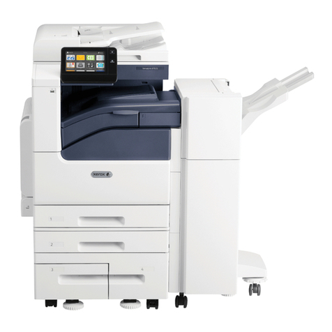
1. Basic composition : Tray1(500 sheets) + MPF(50 sheets)
2. Basic composition + 2 stack optional tray(500 sheets) + MPF(50 sheets)
Machine Spec.(Commercial)
Class.
PINETREE(M611/616)
PINETREE-S(M612/617)
Print Speed(A4)
40ppm
47ppm
Speed for 1st Page
Less than 10 sec
Resolution(dpi)
1200 dpi
Tray Capa.
500 sheets
Paper Size
A5 ~ Legal
MPT
50 sheets
Output Tray Capa.
250 sheets

2
ADF O/X(Capa.)
O (50 sheets)
Options
500 sheets Tray
Memory
512MB
Duplex Unit
O
LCD
Mono, Graphic LCD
Color, Graphic LCD
Interface Port
1 USB/Ethernet
1 USB/Ethernet
Emulation
SDAPL, PCL5e/6, PS3
Compatible OS
Windows XP, Vista, Win7,Win8, Windows sever 2008, Mac OS 10.4
or above, Various Linux OS
Inage Cartridge
3K(M611,M612)
6K(M616,M617)
Weight
19.9Kg(IC inclusive)
Size(W X D X H)
383X386X515(mm)
Paper Spec.
Trays
Load per Media
Paper Size
Base Tray
Plain Paper 500 sheets, Label
50 sheets, Thick 50 sheets
A4, A5, JIS B5, Folio, Letter, Legal,
Executive, Statement
Option Tray
PPR 500 sheets
A4, A5, JIS B5, Folio, Letter, Legal
MPF
PPR 50 sheets, Envelope 5
sheets, Label 15 sheets,
Postcard 5 sheets, Legal 50
sheets or less
Min. 76.2 X 127mm(3 X 5 inch)
Max. 216 X 355.6mm(8.5 X 14 inch)
size or less
Duplexing
PPR 60 ~ 90 gsm
(16 ~ 24 lb)
A4, Letter
ADF Tray
Plain paper 50 sheets
A4, A5, JIS B5, Folio, Letter, Legal,
Executive, Statement

3
500 sheets Option
Paper Tray Unit
Optional Tray
Feed Unit
1.DC Motor 1EA
2.Pick Tire 2EA (EPDM)
3.Gear Arm Assy 1EA
4.Gear Housing Assy 1EA
5.Gear Arm Pivot Assy 1EA
6.BKTAccufeed (PR) 1EA
Frame & External Unit
1.Frame Assy 3EA(MO 2, PR 1)
2.Exterior Cover 4EA
Paper Feed Tray Unit
1. Cassette Tray 1EA
2. Cover Tray 1EA
3. Side Fence _ Left 1EA
4. Side Fence _ Right 1EA
5. End Fence 1EA
Transport Unit
1.PM Motor 1EA
2.Housing Transport 1EA
3.Transport Roller 1EA
Overall View
- Optional Tray

4
Tray Spec.
Class.
Contents
Function
Increase in Paper Load Capacity
Speed
45PPM / 40PPM (A4 SEF기준, KARA-S 45PPM, KARA40PPM)
Paper Load
500 sheets (75 gsm paper) /1stack
Paper Supported
Min. A5 ~ Max. Legal(Xerographic or Business paper)
Paper Weight
16 ~ 90 lb(60 ~ 163gsm) paper
Size(H/W/D)
130.3 mm / 383 mm / 387 mm
Weight
4.5kg a.r.o
Installation
Installation Condition
Environment
The machine should be installed on the following places.
Where good ventilation is provided
Where no obstacle is placed within at least 8 cm on the right side of the machine
for proper operation of the cooling fan.
Where there is no dust and no exposure to the direct sunray.
Where not exposed to cold or hot wind directly from the aircon or heater.
Where within the machine`s operation termperature : 15.6°C ~ 32.2°C at open
space ( -40.0°C ~ 60.0°C: on freight or in house)

5
Installation
Unpacking and Check the Enclosed Accessories
Unpacking
1. Pull out the machine and all the enclosed accessories from the box.
2. Remove the tapes attached inside and outside of the machine.
3. Check the machine and the accessories.
Enclosure List
No
Part No.
Description
QTY
Remarks
1
-
Basic Tray Unit
1
250 sheets
2
LA258058
AC Power cord
1
220V
3
L0025703
USB cable
1
4
M0134105
Quick User Manual
1
5
-
Driver CD
1
2. Cartridge(enclosure)
3. Power cord
4. USB cable
5. Quick User Manual
6. Driver CD(User manual CD inclusive)
7. Paperport CD
8. Line cord
1 Tray1(basic 500 sheets)

6
Optional Tray
Installation
After installing the machine, make sure the following before installing the Optional Tray:
Power off the machine
Pull the power cord off the machine and unplug all the cables at the rear side.
1. Remove all the packaging material and tapes on the tray support
2. Pull out the feed unit
3. Hold the both ends of the support and place it where the machine is installed.
4. Re-install the feed unit. Push it to fit into the machine.
5. Lift up the machine by holding the dented handles at both bottom sides and place it
where it will be installed on.Align the taps, narrow slit and connectors on the tray to the
bottom side of the machine correctly. Place the machine onto the tray and make sure of
the correct match again.

7
The power of the machine must be off when installing the optional tray on or removing
it from the machine.
Image Cartridge
Installation
1. Open the front cover on the upper side.
2. Hold the handles of the cartridge and lift and pull it outside.

8
3. Remove the packaging material from the cartridge.
Do not touch the drum under the cartridge by bare hands.
4. Hold the cartridge by the handles and shake it lightly so that the toner can be evenly
distributed.
5. Hold the cartridge by the handles and align the guides of both sides to the guide grooves
of the machine.
6. Push it until it clicks into the machine.

9
7. Close the front cover. Make sure both sides of the cover clicks shut.
Check if MPT(multi-purpose tray) is also closed. Closing the front cover with the MPT cover
open may cause malfunctions.

10
Maintenance
PM (Preventive Maintenance)
Customer Changeable Items
Items
Life Cycle
Toner Cartridge
Built-in : 3K (M611/M612), 6K (M616/M617)
Standard : 13K
Drum Unit
45K
Condition :
1. The above life cycle is measured based on 5% coverage onA4 size paper.
2. Standard temperature and humidity
3. The life cycle values are subject to change upon the envronment and printing
conditions.
Other Maintenance Items
Class.
Model Name
Parts
Life Cycle
M611/612
M611/M612/M616/M617
Fuser
120K
Tray Acufeed roller
120K
Transfer roller
120K
MPTSeparation Pad
30K
ADF Separation Pad
20K
The service life of the machine is 5 years or 100,000 sheets.
The above consumables should be complied with each replacement cycle since they may
directly affect the print images and the mechanical operations.

11
Detailed Description
IMAGE PROCESS
Electric Charge
-1540V is supplied from HVPS to Charge roller and around -900V is charged on the drum
surface by this.
Laser Exposure

12
Laser beam is projected onto where the image is generated and the potential on that area
is dropped by around -300V making `latent images`.
Development
At the exposure step the toner charged around -550V thru Deveoper Roller and Doctor
Blade is attached on the latent image area made by laser beam, and makes images on the
drum surface.
Transfer

13
At the development step, the images are generated on the drum surface by the transfer of
toner. By this time the transfer roller supplied with around +2000Vpulls and transfer the
toner which was making images on the drum to the paper without settlement yet.
Cleaning
After trasferring the toner to the paper, the little remainder of the toner on the drum is all
collected into a space for the wasted toner by Cleaning Blade before getting close to the
area of Charge Roller.

14
MFP Overview
MFP Components
This manual suits for next models
3
Table of contents
Other Sindoh All In One Printer manuals
