From the library of Superior Sewing Machine & Supply LLC - www.supsew.com
,,,,,,,,,,,,,,,,,,,,,,,,,,,,,,,,,,,.,,,,,,~•"'""'-•"•'""'""Nu,,,.,,,
0
,,,,",,,,,,,.,,,,,,,.,,,,,n,,
0,,,,,,,,,,,,,...,
Fig.
7.
Threading
Wire
164196
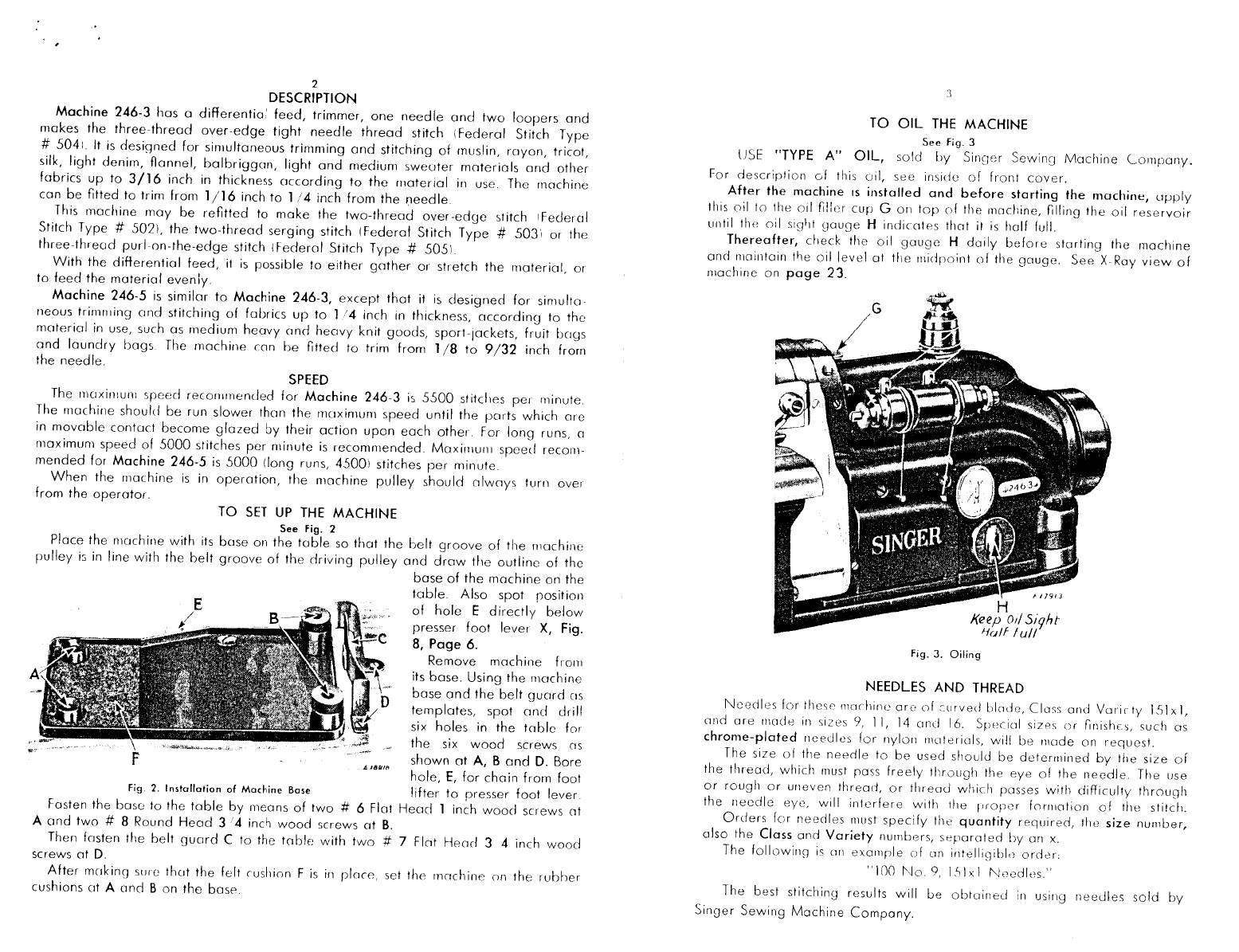
TO
THREAD
THE
RIGHT
LOOPER
(For
Three-Thread
Tight
Stitch)
See
Figs.
8,
9
and
10
L
/792~
CAUTION:
When
threading
right
looper,
be
sure
that
there
is
no
loose
loop
of
thread
on this
looper
to
cause
thread
breakage.
(See
Fig.
9).
Fig.
8.
Threading
Right
Looper
£19132
7
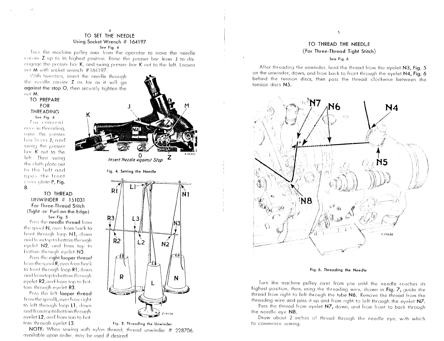
Turn
the
machine
pulley
over
from
you
until
the
needle
is
ot
its
lowest
posi-
tion.
Then
lead
the
thread
from
eyelet
R3,
Fig. 5, page 4
on
the
unwinder
and
pass it
from
bock
to
front
through
the
thread
guide
R4,
Fig.
8,
down
under
the
tension
guide
R5,
then
over
mid
between
the
tension
discs
R6.
Pull
the
front
cover
plate
P
forward,
pass
the
thread
down
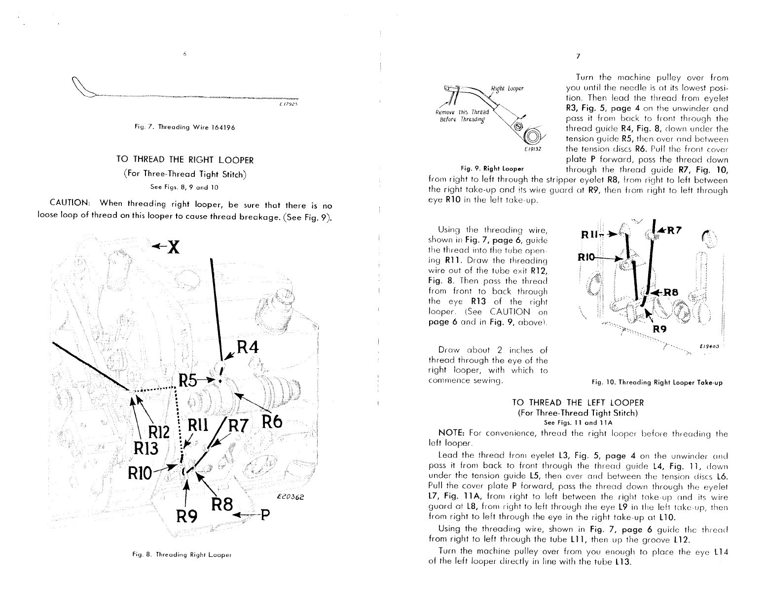
Fig.
9.
Right
looper
through
the
thread
guide
R7,
Fig. 10,
from
right
to
left
through
the
stripper
eyelet
R8,
from
right
to
left
between
the
right
take-up
and
its
wire
guord
ot
R9,
then
from
right
to
left
through
eye
RlO
in
the
left
toke-up.
Using
the
threading
wire,
shown
in
Fig. 7, page 6,
guide
the
thread
into
the
tube
open
ing
Rl
l.
Draw
the
threading
wire
out
of
the
tube
exit
Rl2,
Fig.
8.
Then pass
the
thread
from
front
to
back
through
the
eye
Rl
3
of
the
right
looper.
(See
CAUTION
on
page
6
and
in
Fig. 9,
obovel
Drow
about
2 inches
of
thread
through
the
eye
of
the
right
looper,
with
which
to
commence
sewing.
Fig. l
0.
Threading
Right
looper
Toke-up
TO
THREAD THE
LEFT
LOOPER
(For
Three-Thread Tight Stitch)
See
Figs.
11
and
l
lA
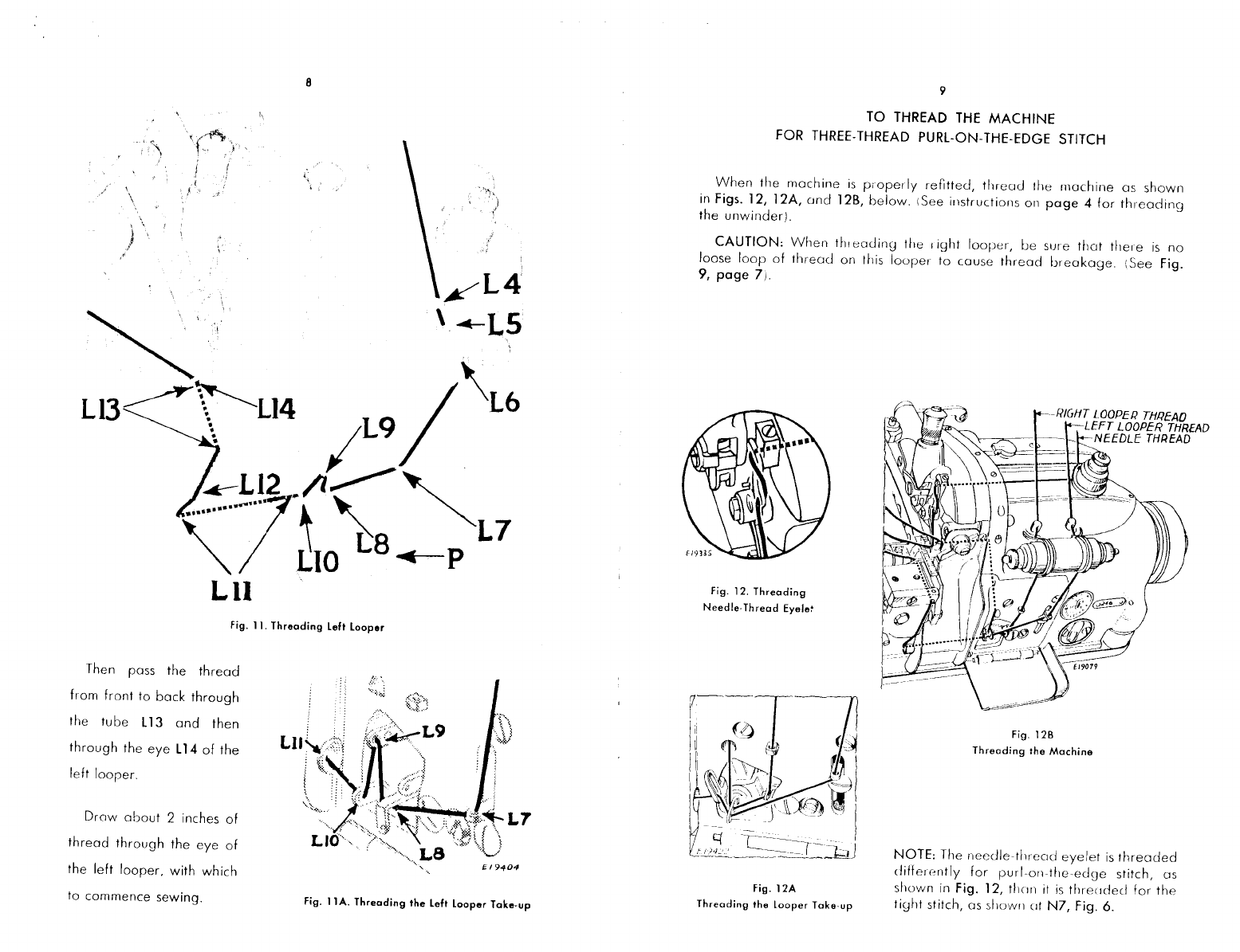
NOTE:
For
convenience,
thread
the
right
loorer
before
th,
coding
the
left
loorer.
Lead
the
thread
fron1
eyelet
L3, Fig. 5,
page
4 on
the
unwinder
c1nd
pass it
from
back
to
front
through
the
thremJ
guide
L4,
Fig.
l
l,
down
under
the
tension
guide
L5,
then
over
and
between
the
tension
discs
L6.
Pull
the
cover
plate
P
forward,
pass
the
threod
down
through
the
eyelet
L7,
Fig. l l A,
from
right
to
left
between
the
right
toke-up
cind its
wire
guard
at
L8,
from
right
to
left
through
the
eye
L9
in
the
left
tc1ke
ur,
then
from
right
to
left
through
the
eye
in
the
right
take-up
at
Ll 0.
Using
the
threading
wire,
shown
in
Fig. 7,
page
6
guide
the
thread
from
right
to
left
through
the
tube
Ll
l,
then
up
the
groove
L12.
Turn
the
machine
pulley
over
from
you
enough
to
place
the
eye
L
14
of
the
left
looper
directly
in
line
with
the
tube
L
13.