Sinlion 4850 User manual

Li-ion Battery User Manual
1
4850Energy Storage Module
User Manual

Li-ion Battery User Manual
2
Index
1.Product specification............................................................3
2. Appearance and size...................................................................4
3.Product introduction ...............................................................5
3.1 Panel introduction...................................................5
3.2 Electrical connection..........................................6
3.3 Definition of communication interface...........8
3.4 Module parallel solution.....................................9
4.Safety precautions ...............................................................11

Li-ion Battery User Manual
3
1.Product specification
48V50AH System specification
1.
Nominal Characteristics
1.1
Rated voltage V
51.2
1.2
Nominal capacity AH
50
1.3
Norminal Energy WH
2560
2.
Mechanical Characteristics
2.1
Weight kg
30
2.2
Length mm
591
2.3
Width mm
440
2.4
Height mm
132(3U)
2.5
Cooling type
Natural air cooling
2.6
Installation method
Cabinet
installation
2.7
Protection mode
IP21
3.
Electrical characteristics
3.1
Voltage Range V
40---58.4
3.2
Maximum charging voltage V
58.4
3.3
Charge current A
10
3.4
Maximum continuous charge current A
50
3.5
Standard discharge current(25±5℃)A
25
3.6
Maximum discharge current A
50
3.7
Electrochemistry System
LiFeCoPO4
3.8
Capacity of cell AH
25
3.9
Cell model
N/A
3.10
Cells number
32
3.11
Permutation of cells
2P16S
3.12
Communication
RS485,CAN
3.14
Maximum number of parallel Module
8
3.13
Battery protection
Over temperature,
over-voltage, over
current,
under-voltage
3.14
Operating temperature-Charge ℃
0℃~45℃
3.15
Operating temperature ℃
-20℃~55℃
3.16
Storage temperature) ℃
-20℃~35℃
3.17
Humidity
5%~95%
3.18
Altitude m
Max. 2,000m

Li-ion Battery User Manual
4
3.19
Standby power
<10mA
3.2
Dormancy power
<1mA
4850Energy storage module use LiFeCoPO4 25Ah soft-pack Battery Core ,Packing as
2P16S.
2.Appearance and size
Module Size:W440mm*H132.5mm*D591.7mm
Module Weight:30kg
Installation method:Cabinet installation
Protection mode:IP21
3.Product introduction
3.1 Panel introduction

Li-ion Battery User Manual
5
RUN for running indicator,always green bright when charging and
discharging,green bright flicker on standby;ALM is a warning indicator
,Red bright flicker when there's alarm.
OUT+ is an orange special connector for energy storage,OUT- is a black
special energy storage connector.levels of protection is IP67.
3.2 Electrical connection
3.2.1 Application scenarios
Energy storage batteries, photovoltaic panels, hybrid inverters and other optical
storage microgrid system, can be connected to the grid, also can run off the grid.

Li-ion Battery User Manual
6
3.2.2 Electrical connection
Hybrid Inverter Communication cable 4850Energy storage module
A schematic diagram of the connection between 4850 energy storage module and
energy storage inverter
A schematic diagram of energy storage inverter interface

Li-ion Battery User Manual
7
The picture above is a manufacturer's energy storage inverter,the connection form and
cable specification of the energy storage module are shown in the following table:
Hybrid Inverter
Battery
Connection
code
Functional
description
Interface name
Cable specification
J
BMS communication
port
RS485/CAN
8 core shielded
twisted pair
H
Battery +
OUT+
5AWG red
H
Battery -
OUT-
5AWG black
The energy storage module OUT+ and OUT- are connected with the energy storage
inverter BAT positive pole and the BAT negative pole respectively through the cable. The
RS485/CAN communication interface of the energy storage module is connected to the
BMS communication port of the energy storage inverter through the 8 core shielded twisted
pair line. After the connection is completed, turn on the POWER power switch .

Li-ion Battery User Manual
8
3.3 Definition of communication interface
Code
Definition
1
CANH1
2
CANL1
3
RS485-A
4
NC
5
RS485-B
6
ISOGND
7
RX
8
TX
The 4850 energy storage module panel has two RJ45 communication interfaces.
Each communication interface includes the communication mode of CAN and
RS485, and the 8 core shielded twisted pair wire is connected with the
energy storage inverter.
Li-ion Battery User Manual
9
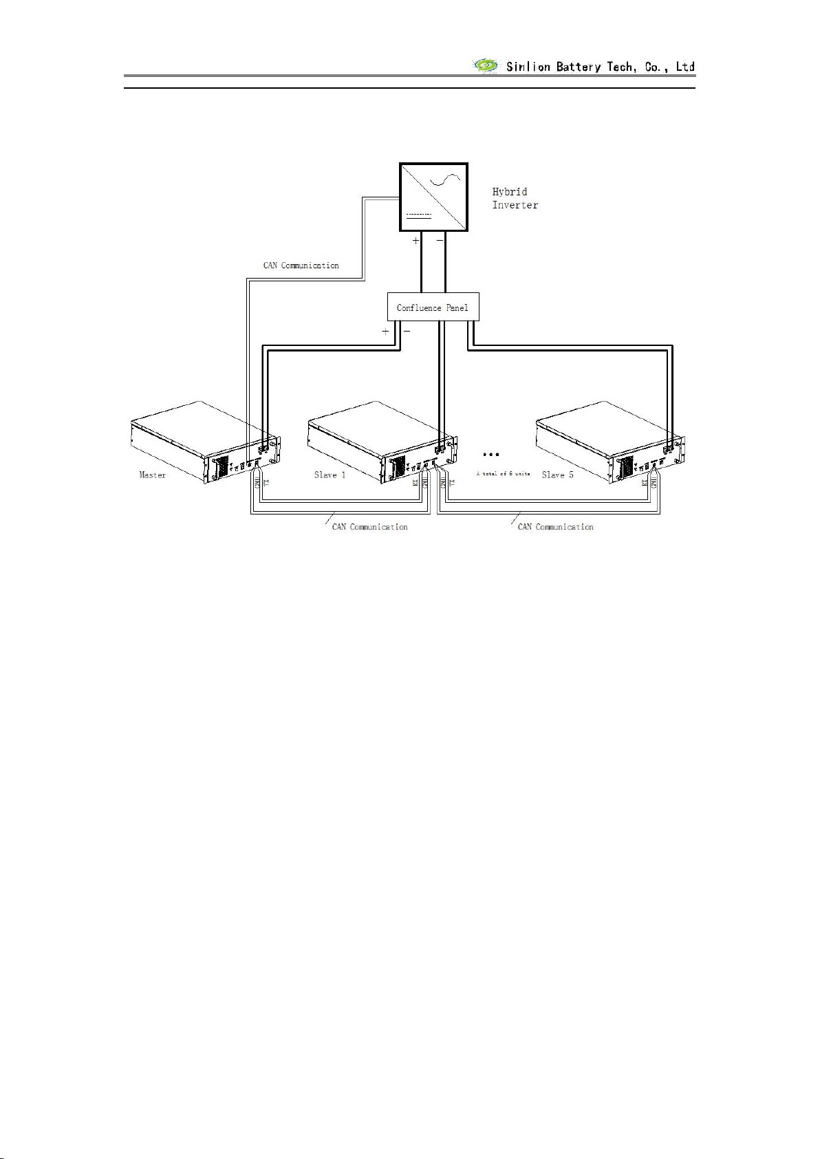
3.4 Module parallel solution
4850 the energy storage module can be used in parallel and the maximum
number of parallel units is 6.
Parallel installation steps:
1.the Master and the slave CAN communication have been connected.
2.8 core shielded twisted pair is used to connect host TX to slave 1 RX,
slave1 TX to slave2 RX,and so on, to complete communication connection.GND
must connected.
3.OUT+ and OUT- are connected to the confluence box through the cable,
and the confluence box is connected with the inverter.
4.Configure the master slave address through CAN debugging software, see
the following table.

Li-ion Battery User Manual
10
Code
Function code
Frame ID
data0
data1
data2
data3
data4
data5
data6
data7
0x1FF
Standard
frame
1:Set the number
of slave machines
the number of slave
machines
00
2:Set the address
of slave machines
the address of slave
machines
00
3:Set the
equipment
working mode
0: slave
1: master
00
4: Start
automatic
allocation of ID
1:Start (only
functional when
pre-configuration of
the master and slave
is set effective)
00
6:Set the PCS
type
0:Trinasolar
1:SOLAX
2:SOFAR
3:VICTRON
4:GoodWe
5:keHua
7:SMA
00

Li-ion Battery User Manual
11
4.Safety precautions
Safety precautions
It must be operated by professional electrical personnel or trained
technicians.
Ensure that the power switch is disconnected during installation.
Please check the material carefully before installation. If there is any
missing or damaged, please do not install dangerous.
The installation position requires waterproof, moisture proof and good
heat dissipation.
When installing, you must wear insulating gloves. Please do not carry
large or too long metal ornaments. The metal tools need to be wrapped
with insulation tools to avoid short circuit risk.
When installing, it is forbidden to contact the total and negative load
of the battery pack at the same time, so as to avoid high voltage hurting
people.
When installing, do not drop debris into the module, otherwise it may
cause instability or damage to the system. It is forbidden to shake the
battery module in the shell, prevent the internal resistance of the wire
loosening, increase the temperature, and cause the battery collision
risk.
All modules must be connected correctly before they can be electrical
tested, and the plug is not allowed when power on. Otherwise, there will
be risks of electric shock or burnout of modules.
Non-professional personnel are forbidden to disassemble the module shell,
and not to touch the internal circuit boards, so as to avoid causing
electric shock accidents.
It has not been confirmed by the manufacturer's technical personnel that
the system is not allowed to be modified or used in other projects, so
as to avoid serious accidents.
Table of contents
Popular Camera Accessories manuals by other brands

Panther
Panther Lightweight Jib operating instructions

Bioenno Power
Bioenno Power BLP-0490M user manual

edelkrone
edelkrone WING 3 user manual

Bradley Engineering
Bradley Engineering Micro Controller operating instructions

Ikelite
Ikelite ULTRAcompact 6270.25 quick start guide

Phottix
Phottix Indra360 TTL instruction manual


