LG LGES-5048 Original operating instructions

LGES-5048 QUICK INSTALLATION INSTRUCTIONS
PART 1
QUICK
INSTALLATION
BATTERY
CONNECTION
PART 2 PART 3
WiFi
CONFIGURATION
340- 00567- 00

Step 1. Instructions For Quick Installation
Step 2. SOP of Battery Connection Step 3. WiFi Configuration Instruction Step 1. Instructions For Quick Installation Step 2. SOP of Battery Connection Step 3. WiFi Configuration Instruction
EBattery wire Assembly and Connection
DInstallation
Inverter could be locked for
anti-theft,if it is needed.
Ground cable is needed
connecting to ground plate
on grid side
Installation Space
A
Upward
Downward
Front
Left and right side
-------------------------- 300 mm
---------------------- 500 mm
----------------------------- 300 mm
------------- 200 mm
≥300 mm
≥200 mm ≥200 mm ≥500 mm
≥500 mm
Fix the Wall Bracket
C
BDimensions For Drilling Holes
120mm
240mm
5- Ø 10*80mm depth
Wall Bracket
Self-tapping
Screws
Battery Terminal Use Special
tool to crimp
Battery Cover
Waterproof Ring
Cable
InsulatorScrew Cap
A External diameter of the wire
C Length of bare wire
10~12mm
35mm 2
Approx.10mm
B Sectional area of conducting
materials
Expansion Pipe
250mm
265mm
125mm
Description
A B
C
Size
DC Breaker 125A
Red Cable
Black Cable
Reversed polarity will damage
the inverter!
Pan Head Screw
Hexagon Head Screw
Special tool is
required for crimping
Note: 1 To Battery communication cable
②To Smart meter communication cable (could be extended to max 100m)
AC Cover
3m
14
10m
RESU LV
battery
EzMeter
House
House
CT N
L
Grid
Insulator
Seal Ring
DRED
Connector
Nut
RS485
Board
The
Insulator
Single Hole
Seal Ring
Screw
Cap
Cable
Cable
Screw Cap
Pin Connector
Positive Connector
Negative Connector
MC4 Series
7mm
7mm
2.5-4mm2
DC cable should be dedicated PV cable (suggest using 4mm2 PV1-F cable)
DRED connection is only available for Australia and New Zealand.
DRM1/5
1
NO 2 3 4 5 6
Function DRM2/6 DRM3/7 DRM4/8 REFGEN COM/DRMO
Warning
Negative
Terminal
(black)
Positive
Terminal
(red)
DC Cable Assembly and Connection
AC Cable Assembly and Connection
DRED Cable Assembly
Communication Cable Connection

Step 1. Instructions For Quick Installation Step 2. SOP of Battery Connection Step 3. WiFi Configuration Instruction
AC Breaker*2
DC Breaker
≥125A
House→Grid
Grid
House→Grid
On-Grid Load
CT*1
‘To Smart Meter’
Power Meter
1.Direction of the CT cannot be connected in reverse, please
follow"House→Grid" direction to do the connection
2.AC Breaker≥50A
PV Strings
Battery Back-Up Load
Wiring system For LGES-5048 Hybrid lnverter
Step 1. Instructions For Quick Installation Step 2. SOP of Battery Connection
Step 2. SOP of Battery Connection with LG Energy Solution RESU
Step 3. WiFi Configuration Instruction
Please refer to LG RESU Installation Manual for full battery installation instructions.
LG RESU
Pic.1 Pic.2
Pic.3
Pic.4
Pic.5
Pic.8
Pic.7 Pic.9
Remove the top cover. Hold both
sides of the top cover and pull it
upwards(Refer to Pic.2)
Make sure that the inverter and the
battery pack is turned off before
connecting the battery pack to the
inverter (Refer to Pic.1)
Connect the 35mm
2
power cables...
(a) Pass power cables through grommets and connect M8 lug
(b) Remove clear plastic terminal cover and connect cables - torque 6Nm.
Be sure not to reverse polarity.
(c) Replace terminal cover
(d) connect grounding wire through grommet
with 6mm eyelet and (see RESU LV battery
Installation manual)
(e) apply silcone sealant or putty to all
grommets.
(a) Cut off the plastic skin of the cable.
(b) Put the cable through the terminal cover plate.
(c) Plug the metal part into the M8 terminal lug which in
inverter accessories box, then crimp the terminal
tightly.
(d) Connect the power cable to the terminal block of the
hybrid irverter and restore the inverter terminal cover plate.
(Refer to Pic.4)
The other side of "To Battery " cable should be connected
CAN port on the top side of LG battery (Refer to Pic.6)
On LGES PV Master,should
choose the right battery type
used in your system by"Battery
Model" selection (Pic. 8) or
battery communication will fail.
After all connection and
settings done,please
check if battery
communication is OK on
LGES PV Master→Param→
BMS Status, which should
be"Communication OK"
(Pic. 9)
The communication cable for battery is attached on the inverter
(Refer to Pic.5)
Please use this cable as battery communication cable.
There are three DIP switches and three rotary switches
on battery,which should be set as below (Refer to Pic.7):
for DIP switch settings for 2 batteries using RESU Plus, see RESU Installation Manual

1. Power Wi-Fi inverter (or Power on Inverter) on.
2. Power router on.
10.10.100.253
Back
Back Complete
Next
CANCEL
Note:
The 'Solar-WiFi'signal
will disappear after
inverter connects to
WiFi router.Turn off
router or do WiFi
reload operation via
button on inverter if
you need connect to
'Solar-WiFi’once again.
Note:WiFi Configuration could also be done on LGES PV Master App, for details, please download "LGES PV Master Operation Introduction" at
https://www.lgessbattery.com/au/home-battery/product-info.lg
Step 1. Instructions For Quick Installation Step 2. SOP of Battery Connection Step 3. WiFi Configuration Instruction
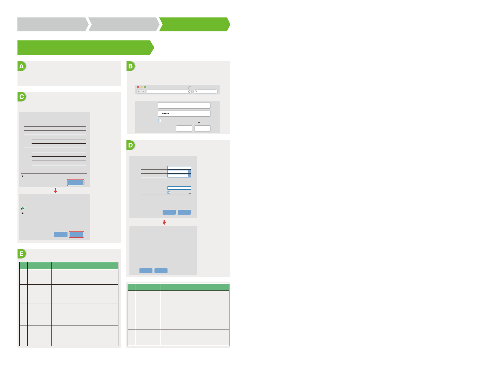
Step 3.Wi-Fi Conguration Instruction
Preparation Connect to 'Solar-WiFi'
Connect to 'Solar-WiFi'
Preparation
ProblemNo. Checking Items
Troubleshooting
Please select you current wireless network
SSID Sec mode Enc type Channel RSSl
Firmware version
router doesn't exist, or signal is too weak, or password is incorrect.
Help: Wizard will help you to complete setting within one minute.
1.6.9.3.38-2.1.38
60:C5:A8:60:33:E1
Enable
Solar-WiFi
10.10.100.253
Disable
WiFi_Burn-in
WPA/WPA2-PSK
AES
WiFi_Burn-in
MAC address
Wireless AP mode
SSID
Router SSID
Encryption method
Encryption algorithm
Router Password
IP address
Wireless STA mode
Note: When RSsl of the selected Wi-Fi network is lower
than15%, the connection may be unstable, please select
other available network or shorten the distance between
the device and router.lf you wireless router does not
broadcast SSID, please click‘Next'and add a wireless
network manually.
WiFi-Test WPA2-PSK AES 06 54%
1.Click ‘Start Setup’
The Wi-Fi module
parameters please
refer to 'Device
information'
column above.
1.Fill in router password and click 'Next'
Network name (SSID) WiFi-Test
Encryption method
Encryption algorithm
Password (8-63 bytes)
★Note: case sensitive for SSID and Password.
Please make sure all parameters of wireless network
are matched with router, including password.
Router password
Add wireless network manually:
Please enter the wireless network password:
Save success!
Please make sure
all parameters of
wireless network
are matched with
the router's,
including password.
Click 'Complete', the current configuration will take effect
after restart.
lf you still need to configure the other pages of information,
please go to complete your required configuration.
Configuration is completed, you can log on the
Management page to restart device by click on 'OK' button.
Confirm or complete?
lf the router is not in
the site list, please
refer to No.4 in
'Troubleshooting'.
Cannot Find
Solar-WiFi Signal
1
2
3
4
1.Make sure inverter is powered on;
2.Move your smart device closer to inverter;
3.Restart inverter;
4.Do "WiFi Reload' operation refer to user manual.
1.Try password: 12345678;
2.Restart inverter;
3.Make sure there is no other device connected to
Solar-WiFi;
4.Do 'WiFi Reload' operation and try again.
1.Make sure user name and password you use are both
admin;
2.Do 'WiFi Reload' operation and try again;
3.Try another browser (suggest use Google, FireFox, IE,
Safari etc.);
4.Make sure website you log in is 10.10.100.253
1.Move router closer to inverter or use a Wi-Fi repeater
device;
2.Connect to router and login the setting page to check
the channel it uses. Please make sure the channel is
not bigger than 13. Otherwise, modify it.
1.Restart inverter
2.Connect to Solar-WiFi and login again,check the
'SSID", 'Security Mode','Encryption Type'and ‘Pass
Phrase’is matching with that of router or not;
3.Connect to router and login to check if the
connection reaches the maximum amount or not,
and to check the channel of it uses. Please make sure
the channel is not bigger than 13.Otherwise, modify it;
4.Restart router ;
5.Move router closer to inverter or use a WiFi repeater
device.
1.Connect to the router and visit the portal
www.lgresuhomemonitor.com Check the portal is
available or not;
2.Restart router and inverter;
3.Make sure the inverter is registered on the platform.
Cannot connect to
Solar-WiFignal
Cannot login
website
10.10.100.253
Cannot find router
SSID
Back Next
Start Setup
Please select you current wireless network
5
6
Cannot Find
Solar-WiFi Signal
After configuration,
WiFi Led on inverter
blink four times
repeatedly
ProblemNo. Checking Items
1.Wi-Fi name: Solar-WiFi*(* means the last 8 characters of
inverter serial NO.)Password: 12345678
2.Browse website: 10.10.100.253
B-3: Enter User name:admin, Password:admin, click OK
Remember the password(R)
Password :
Admin(U) : admin
WAP/WPA2-PSK
AES
Other manuals for LGES-5048
3
Other LG Camera Accessories manuals

LG
LG LPT-A100L User manual

LG
LG AJ-LAH2 User manual

LG
LG Energy Solution RESU10H Prime User manual

LG
LG CAM Plus User manual

LG
LG ICR18650B3 Owner's manual

LG
LG cam plus CBG-720 User manual

LG
LG RESU 10H User manual

LG
LG HBP10H User manual

LG
LG RESU FLEX Operating and maintenance instructions

LG
LG CHEM RESU10H User manual
Popular Camera Accessories manuals by other brands

Torqeedo
Torqeedo Power 48-5000 Translation of the original operating instructions

ProMediaGear
ProMediaGear GT1 manual

dehn
dehn SET DIGIK Instructions for use

Nauticam
Nauticam NA-LX100II instruction manual

Panasonic
Panasonic AWPH360N - PAN/TILT HEAD Operating instruction

Guilin Feiyu Technology
Guilin Feiyu Technology SPG 2 instructions