Sintes UltraPeen UP-600 User manual

UltraPeen®
SYSTEM OPERATION MANUAL
UP – 600
ULTRASONIC GENERATOR
AND TOOL

SINTES 2
ULTRAPEEN®
TABLE OF CONTENTS
1. SYSTEM SAFETY……………………………………………………………………………....3
2. SYSTEM COMPONENTS……………………………………………………………………...5
3. SYSTEM SET- UP…………………………………………………………………..….……... .9
3.1. MAINS POWER CONNECTION...………………………………………………….…...9
3.2. TOOL POWER CONNECTION...…………………………………………………...9
4. ULTRASONIC TOOL...………………………………………………………………………10
5. CHANGEABLE WORKING HEADS……………………………………………………...11
6. SYSTEM OPERATION RULES...………………………………………………………..15
6.1 EQUIPMENT OPERATION………….………………………………...15
6.2 SAFETY………………….………………………………………………..15
6.3 OPERATION ORDER……………….…………………………………..15
6.4 MAINTENANCE AND REPAIR………………………………………..17
7. TECHNICAL SPECIFICATIONS…………………………………………………………18
8. LIMITATION OF WARRANTY………………………………………………………….…19
9. SERVICE………………………………………………………………………………….…20

SINTES 3
ULTRAPEEN®
1. SYSTEM SAFETY
1. SYSTEM SAFETY
Read this manual thoroughly and follow all directions to assure maximum
safety during operation.
Ultrasonic peening by UP–600 system (Ultrasonic Generator and Tool) is to be
performed by qualified technical personnel only.
The UP–600 system is an electro-mechanical device that under certain
circumstances could present an electrical shock hazard to the operator.
Only qualified technicians, licensed by the Manufacturer should perform the servicing
of UP–600 system.
Performance of procedures other than those specified herein may result in hazardous
exposure to ultrasonic energy or electric shock. To avoid electric shock, do not remove
the case covers from the Ultrasonic Generator.
Plugging the Generator unit into a socket that supplies improper voltage may cause the
Generator to malfunction or create an electric shock or fire hazard.
Proper system grounding cannot be ensured unless the unit is connected to properly
wire three prong 220-240 or 110-120 VAC (depending on the model) single-phase
outlets with a sufficient current rating.
The Generator’s electrical supply cord should not be plugged into a device (e.g. “power
strips”, “gang plugs”, etc.) other than an industrial grade wall socket or a standard
gang plug with an appropriate wire cross-section and current rating. Any other use
could cause significant changes in voltage that could result in malfunction of the UP–
600 system.
Do not restrict the airflow to the Ultrasonic Generator by covering or enclosing it in a
sealed housing while in operation. The air should circulate through the unit during
operation to facilitate proper cooling of electronic components.

SINTES 4
ULTRAPEEN®
1. SYSTEM SAFETY (continued)
Do not immerse the UP-600 system in water or other liquids. The system is not sealed
against liquids and exposure may result in damage to the equipment, create an electric
shock hazard, or fire hazard.
Due to the general operating principles of the UP-600 system, the equipment is not
suitable for use in environments where danger of explosion exists.
When the ultrasound output power is ON, do not touch the tip of the transducer when the
working head is removed; doing so may result in exposure to hazardous ultrasonic energy.
Do not remove or disconnect the grounding prong on the line cord plug.
Wearing of hearing protection means during operation of the system is highly
recommended, using special noise-absorbing earplugs or headphones. The operating
frequencies of the UP-600 system are below, within, and above the range of human
hearing. The Tool, while in operation, emits acoustic energy, the power of which
depends upon geometrical size of the processed item and the amplitude of ultrasonic
emitter oscillations and may, in some situations, exceed the noise limit at 80 decibels.
SINTES 5
ULTRAPEEN®
2. SYSTEM COMPONENTS
2.0 SYSTEM COMPONENTS
The UP-600 system is designed for Ultrasonic Peening of materials, parts and welded elements
in manual and robotized modes. The system includes the following components:
The Ultrasonic Generator
The Tool – an ultrasonic transducer with a working head
A Laptop (optional item) with software for recording of the parameters of
UP treatment, remote control and UP optimum application
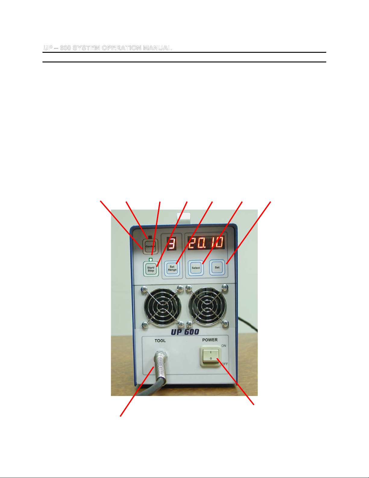
The Front Panel of the Ultrasonic Generator
Figure 1 shows the layout of the front panel of the Ultrasonic Generator.
3 9 8 6 5 4 7
2 1
Figure 1. The Front Panel of the Generator

SINTES 6
ULTRAPEEN
2. SYSTEM COMPONENTS (continued)
Description of the button functions:
1 – Power - Power ON/OFF switch
2 – Cord connecting the Tool to the Ultrasonic Generator
3 – Control – A button with an indicator for verification of the System
4 – Select - By pressing button Select one may set up the next unit of indicator.
First two units indicate time in minutes, following two units – time in
seconds. After choosing the last unit on indicator, the next click
leads to the switched off timer mode to the unlimited time of
treatment that appears as dashed line (- - - -)
5 – Set Range - A button with a digital indicator for setting up the level of
ultrasonic energy
6 – Start/Stop - A button to start/stop the ultrasonic oscillations of the Tool
7 – Set - By pressing Set button one can change the value of
selected/blinking unit
8 – Status indicator of Start/Stop mode of the Tool
9 – Status indicator for Control button

SINTES 7
ULTRAPEEN
2. SYSTEM COMPONENTS (continued)
The Rear Panel of the Generator
Figure 2 shows the rear panel of the Ultrasonic Generator.
3 4
1 2
Figure 2. The Rear Panel of the Generator
1–Power Supply connector (shown with the supply cord not attached)
2–Safety fuse
3 – Connector for robotized application of UP system
4 – RS-232 Interface for connection to a PC
SINTES 8
ULTRAPEEN
2. SYSTEM COMPONENTS (continued)
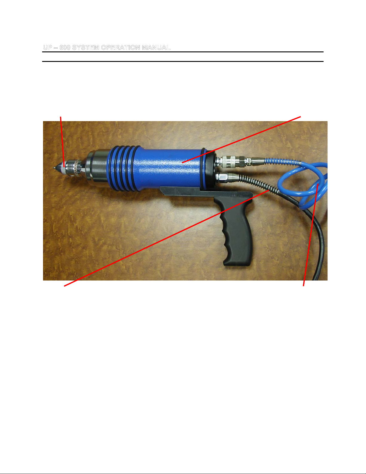
Ultrasonic Tool
Figure 3 shows the Ultrasonic Tool.
2 1
4 3
Figure 3. The Ultrasonic Tool
1 – Holder of Ultrasonic Tool
2 – Replaceable Working Head
3 – Tube for compressed air. The cooling of tool by compressed air is
required for ultrasonic treatment. Air pressure is 25-35 psi.
CAUTION: Do not operate UP system without cooling of Tool by compressed air. The
exceptions could be the verification the condition of system (5-7 seconds) and/or short
demonstration (no more than 1 minute).
4 – Cord connecting the Tool to the Ultrasonic Generator

SINTES 9
ULTRAPEEN
3. SYSTEM SET-UP
3. SYSTEM SET- UP
CAUTION: Plugging the Ultrasonic Generator unit into a socket, which supplies improper
voltage and/or current rating, may cause the Generator to malfunction or create an
electric shock or fire hazard.
CAUTION: The Generator Electrical Supply cord should not be plugged into a device (e.g.
“power strips”, “gang plugs”, etc.) other than an industrial grade wall socket or a standard
gang plug with an appropriate wire section and current rating. Any other unauthorized
use could cause significant changes in voltage that could result in an electrical fault
indication.
3.1. MAINS POWER CONNECTION
Verify that the Mains Power Switch “Power” on the front panel of the Generator is in the
OFF position.
Plug the female end of the supplied grounded line cord into the Mains Power Supply
connector in the rear of the Generator (see Figure 2). Plug the other end of the line cord
into a properly grounded three prong 220-240 VAC (single phase) or 110-120 VAC
grounded socket receptacle. UP-600 system with output power up to 500 Watts requires
a mains power circuit with a nominal fuse rating of 8.0 Аmps for 110/120 VAC and
4 Amps for 220/240VAC.
3.2. TOOL POWER CONNECTION
The ultrasonic frequency voltage is supplied to the Tool via permanent connector in the left
lower corner on the Generator’s front panel (see Figure 1).

SINTES 10
ULTRAPEEN
4. ULTRASONIC TOOL
4. ULTRASONIC TOOL
Figure 3 shows the Ultrasonic Tool.
The Ultrasonic Tool consists of a metal case, ultrasonic transducer inside the case,
and easy-removable (elastically fixed) working head with striker(s) (1, 2, 3, 4or 7
pins). A power cord connects the Tool with the Ultrasonic Generator. There is also
quick connector for cooling of Tool by compressed air. Connect tube with
compressed air to the Tool using quick connector.
The case contains the built-in piezo-ceramic transducer. To activate the Tool it
should be pressed with the force 25-50 N against the treated surface. A cylindrical
spring is situated in the clearance between the transducer and the case.
CAUTION: Do not operate UP system without cooling of Tool by compressed air. The
exceptions could be the verification the condition of system (3-5 seconds) and/or short
demonstration (no more than 1 minute). Make sure that the air for cooling of Tool is
clean and not warm/hot.
CAUTION: According to the regulations for safe operation of ultrasonic equipment with
power higher than 100-Watts, the operator should wear cotton gloves. If the sound of
ultrasonic treatment exceeds allowable level of 80 decibels, headphones should be
used.
The strikers that can be chosen of various diameters are positioned in
special holes at the bottom of working heads. Strikers are made of high
strength steel with high hardness. Figure 4 shows a set of Changeable
Working Heads.
SINTES 11
ULTRAPEEN
5. CHANGEABLE WORKING HEADS
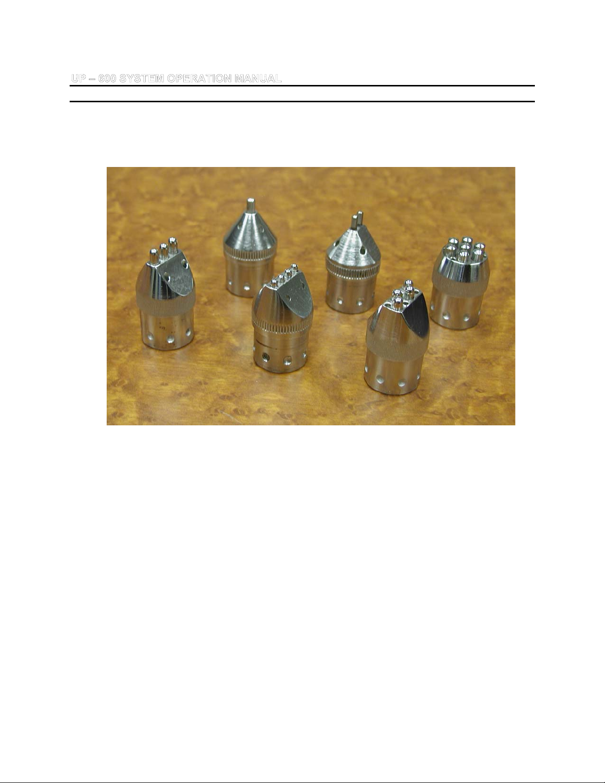
5. CHANGEABLE WORKING HEADS
Figure 4. Standard set of the changeable working heads
Six different working heads are provided with the standard package:
One four-pin working head with the pin’s diameter of 3 mm.
One three-pin working head with the pin’s diameter of 4 mm.
One “zig-zag” four-pin head with the pin’s diameter of 4 mm.
One single-pin working head with the pin’s diameter of 4 mm
One seven-pin working head with the pin’s diameter 5 mm.
One two-pin working head with the pin’s diameter of 3 mm.
SINTES 12
ULTRAPEEN
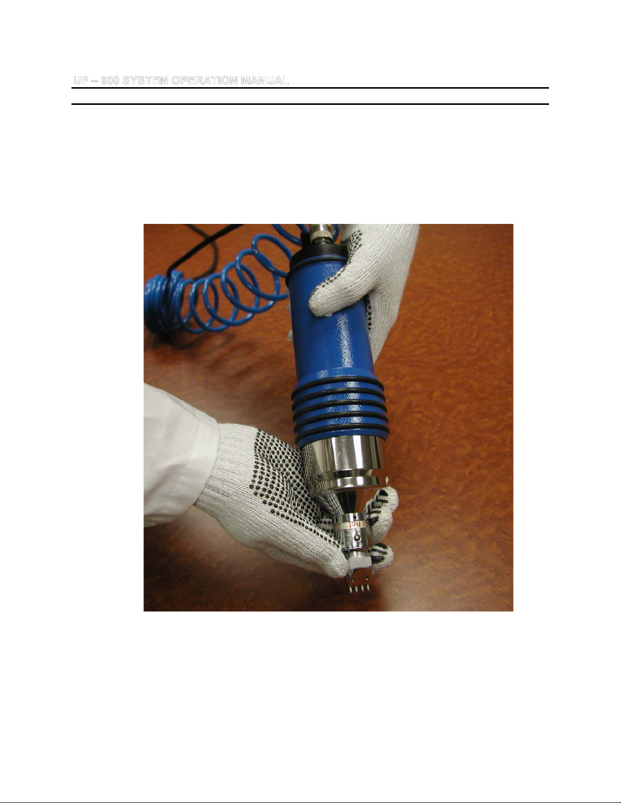
5. CHANGEABLE WORKING HEADS (continued)
The working head could be installed by pushed it onto the tip of the
instrument until the distinctive “click” sound is heard. Make sure that the
certain hole on working head is coaxial to the fixing sphere on the tip of
Tool (Figure 5).
Figure 5. Installing/removing of the working head
SINTES 13
ULTRAPEEN
5. CHANGEABLE WORKING HEADS (continued)
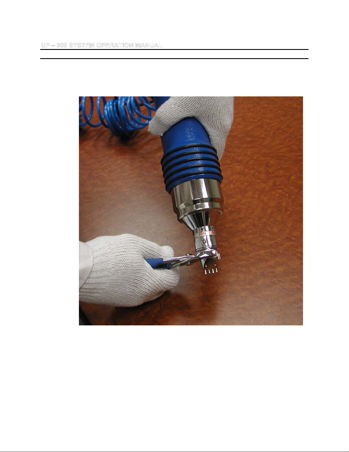
Figure 6 shows the procedure of inserting/removing of working head with
the use of a wrench when additional force is required.
Figure 6. Inserting/removal of working head with the help of wrench when
additional force is required. Rotate working head in both directions slightly,
and remove (or insert) it simultaneously.

SINTES 14
ULTRAPEEN
5. CHANGEABLE WORKING HEADS (continued)
Figure 7 shows the procedure of inserting/replacement of pins/strikers.
Figure 7. Inserting/replacement of pins/strikers

SINTES 15
ULTRAPEEN
6. SYSTEM OPERATION RULES
6. SYSTEM OPERATION RULES
6.1. EQUIPMENT OPERATION
To start the operation of the instrument, turn ON the power switch Power. The Set
Range indicator as well as the time indicator is illuminated.
Set the required operation mode: level of ultrasonic energy (Set Range) in range 1,
2, 3, 4, and time (Select/Set) in minutes/seconds or indefinite time.
Turn ON the unit using the Start/Stop button. Status indicator illuminates in blinking
mode.
Press the Tool against the treated surface with a force of 30-50 N to commence the
Ultrasonic Peening process. After the treatment is accomplished, reduce the force on
the instrument to stop the oscillations of the transducer.
Press the Start/Stop or Power buttons to switch OFF the power supply unit.
Ultrasonic Generator has a built-in RS-232 interface for connection with a PC. PC
COM socket for the connection is positioned on the rear panel of the Generator. For
the connection with the computer, only the signals RxD, TxD, GND are used. The
connection speed is 9600 bit/sec. The software for recording of the parameters of
UP treatment, remote control and UP optimum application is an optional item.
6.2. SAFETY
In accordance with the safety rules against electrical shock hazard, the unit is
manufactured along the requirements of the protection standard # 1 in compliance
with IEC 601-1.
Before commencing the work, operator should make sure that the working place
where ultrasonic equipment is used has special sockets connected to the protective
external grounding.

SINTES 16
ULTRAPEEN
6. SYSTEM OPERATION RULES (continued)
6.3. OPERATION ORDER
6.3.1 Set Mains Power Switch Power to OFF position.
6.3.2 Install the required working head with strikers.
6.3.3 Plug power supply unit cable into the unit and Mains Power Supply 110-
120 VAC, 60 Hz or 220-240 VAC, 50 Hz (depending on design of
Generator and local power supply standards).
6.3.4 Switch to ON the power switch Power. Indicators Set Range and
Select/Set are illuminated.
6.3.5 Press and hold the Control button for 3 – 5 seconds. This will start
oscillation of Tool. If Control indicator illuminates in green (after 1-2
seconds in red) – the system is in working condition, if in red permanently
during pressing of the Control button – system is not ready for operation.
In last case, adjustment or repair of system is required and could be done
by Manufacturer of the equipment.
6.3.6 Set the level of ultrasonic energy with Set Range button: 1- minimum
level; 2and 3- intermediate levels; 4- maximum level.
6.3.7 Required operation time may be set by Select/Set buttons. During the
setting the digits on the indicator will flash.
6.3.8 Switch ON the ultrasonic oscillation of the Tool by Start/Stop button. The
Status indicator starts to flash, and the operation time digits on the timer
illuminate continuously.

SINTES 17
ULTRAPEEN
6. SYSTEM OPERATION RULES (continued)
CAUTION: Do not operate UP system without cooling of Tool by compressed air.
The exceptions could be the verification of the condition of system (3-5 seconds)
and/or short demonstration (no more than 1 minute). Make sure that the air for
cooling of Tool is clean and not warm/hot.
6.3.9 Press the Tool against the treated part with a force of 30–50 N to start the
Ultrasonic Peening process. Status indicator illuminates continuously
during the treatment and the Select/Set timer starts the countdown.
When the timer reaches zero, the Tool automatically switches off. The
treatment also could be interrupted at any time and than continued again
until the end of pre-set time.
6.3.10 If necessary, the operation may be stopped and the operation time may
be re-set (Select/Set indicator blinks). The level of ultrasonic energy may
be re-set also by Set Range button.
6.3.11 The system is designed to protect the Tool from overheating. In case of
overheat of UP system, the ultrasound is switching of automatically, and
letters OH (overheat) illuminates on the indicator instead of time. Promptly
suspend operation for no less than half an hour. The Power button should
be turned to the OFF position. The treatment may be continued after the
Tool cooled down (not less than in half an hour).
6.4. MAINTENANCE AND REPAIR
While on warranty, technical maintenance and repair of the System should be done
by Manufacturer or its representative only. Extended warranty could be arranged for
different terms.

SINTES 18
ULTRAPEEN
7. TECHNICAL SPECIFICATIONS
7. TECHNICAL SPECIFICATIONS
Physical Dimensions
Size
Dimensional sizes of Tool (without handle), mm 340 х80 х80
Dimensional sizes of Ultrasonic Generator, mm 270 х230 х140
Weight
Mass of Tool , kg 3.9
Mass of Ultrasonic Generator , kg 6.8
Environmental Requirements
Permissible operating temperature of environment, оC from –30 to +45
Permissible humidity of environment, % to 80
Power Requirements
Voltage of electrical circuit, V 110-120 or 220-240
Frequency of power voltage, Hz 50 – 60
Maximum consumed power, W 500
Other Parameters
Frequency of ultrasonic oscillations, KHz ~ 22
Cooling compressed air
opressure 25-35 psi
otemperature should not exceed 21°C

SINTES 19
ULTRAPEEN
8. LIMITATION OF WARRANTY
8. LIMITATION OF WARRANTY
The UP-600 system is designed for maximum operator safety and incorporates
built-in safety devices. Any modifications to these safety features will void the
warranty. The Manufacturer assumes no responsibility for consequential
damages incurred due to modifications to the said equipment.
Under no circumstances shall Manufacturer be liable to the Purchaser or to any
other person for any incidental or consequential damages or loss of profit or
product resulting from any malfunction or failure of this device or due to
unexpected force-major circumstances.
Within the Warranty period, the Manufacturer will repair or replace free of charge,
at his sole discretion, all parts that are defective due to poor workmanship upon
shipment of the unit to the Manufacturer (the costs of shipment to and from the
Purchaser are not covered under the Warranty and are the sole responsibility of
the Purchaser).
Manufacturer’s liability, whether based on warranty, negligence or other cause,
arising out of and/or incidental to sale, use or operation of the device elements, or
any part thereof, shall not in any case exceed the cost of repair or replacement of
the defective equipment, and such repair or replacement shall be the exclusive
remedy of the Purchaser, and in no case will be responsible for any and/or all
consequential or incidental damages including without limitation, and/or all
consequential damages arising out of commercial losses.
The warranty does not apply and may be voided for equipment subject to unauthorized
modifications, repair, misuse, abuse, negligence or accident.
Equipment that in our judgment shows evidence of having been used in violation of
operating instructions will be ineligible for service under this warranty.

SINTES 20
ULTRAPEEN
9. SERVICE
WARNING: To avoid electric shock, do not remove the case cover from the
Ultrasonic Generator and Tool. There are no user-serviceable parts inside any of
these components.
IMPORTANT NOTICE: For the protection of employees, shippers, receivers,
various personnel, and to remain in compliance with Transit Laws, material returned
to the Manufacturer or its designated representatives must be rendered free of any
hazardous, noxious, or radioactive contamination.
WHERE TO WRITE:
Should the user of this device have any questions or comments as to its
specifications, use, limitations, or maintenance, the Manufacturer’s Service
Representative can be contacted as follows:
Structural Integrity Services Inc.
15 North Park Road, Unit 212
Thornhill, ON L4J 0A1
Canada
Tel: (416) 917-1519
Email: [email protected]
Website : www.sintes.ca
Table of contents
Popular Tools manuals by other brands

Skil
Skil 1703 instructions

Alpha Professional Tools
Alpha Professional Tools Alpha BAB3GRD instruction manual

Makita
Makita BHR262 instruction manual

Sioux Tools
Sioux Tools 658 Instructions-parts list

HAUL MASTER
HAUL MASTER 30131 Owner's manual & safety instructions

CommScope
CommScope FIST-RSKG-16 Installation instruction


