springwasher (3). balancenut (4). drivewasher
(5)
wave washer
(6)
and
then removeretainingring(7) andwave washer
(8).
Still
grippingrandombalancebody(1
l),
tapoutmountingpadshaft(9)
assemblyat the rearendto removethe assembly fromtherandom
balance body with wave washer
(15).
Remove fixing
screw
(14)
from padmountingshaft (9) and tap this padmounting shaft
(9)
throughbearing (10).
Remove
two
screws
(38)
andtakeoff motor cover
(49).
Grip
body
(16)
in a vise fittedwith soft jaws and remove four rotor screws
(31) andtake off rotorcover (29). Fromthe frontendof thetool,tap
the
end
of rotorshaft (18) to drivethe motor assemblyout of the
body(16). Notehowthe slot inthe side of thecylindei(26) has to
line up with the portinthe body (16). Grip rearplate(28) andtap
the rearendof the rotorshaft
(18)
throughthe rearplate(28) and
bearing(24). Remove rotor blades (23), shims (20). and unscrew
set screw (22) from rotor (21) and remove rotor shaft (18). Note
locationof set screw (22) hole
in
rotor(21) inpositionwith flat on
rotorshaft (18) andremoveshims(20).Tap frontendof rotorshaft
(18)throughfrontplate(17)to removebearing(19)fromfrontplate
(17).
Unscrew cap screw (32) and take out throttle spring
(33).
pushrod(45). andO-ring(34). Do notremovevalve bodybushing
(46) frombody(16).Take off retainingring(35), removeplatewasher
(36)
andrubberwasher (37). Removescrew(44)andlockwasher
(43). Pulloff regulatorlever (42) andO-ring(41). Carefullypullout
regulator (40) with
two
O-rings (39). Unscrew bolt
(53)
from nut
(54)
andtake off safety lever (52). Take out two
screws
(50)
and
removeleverbracket (51). Remove handlegrip
(57)
andunscrew
handle(58) from body (16) and take off valve lever (55). Remove
muffler (47) and muffler element (48) trom motor cover (49).
Reassembly
Clean all parts andexamine for wear. Use only manufacturer or
authorizeddistributor supplied spare partsand replaceany worn
parts. Lookinparticularforwearonseals,
ball
bearingandblades.
Coatallparts inpneumatictoollubricatingoil, and reassemblein
the reverseorder carefully. Assure allparts are tight and letlever
and regulatormechanisms operate freely. With (ever depressed,
pour
5
miof a suitable pneumatic
tool
oil into inlet bushing and
release.Connect a suitableair supply and run this tool for
2
or
3
seconds to allow the oilto circulate.
Operation Specification
AverageAir Consumption 4.0
dm
(28 scfm)
Air InletThread 114-18NPT
SpindleThread 5116-24UNF
t
Length
8"
(204mm)
Height 5.4" (136mm)
Pad
6"
(150mm)
I
at
60
PSIGl4.2 bar
1
Notes
I.
r
Declarationof Conformity
cc
SiouxTools Inc.
117
LeviDrive,Murphy,
NC
28906,
U.S.A.
declareunder our soleresponsibilitythat the product
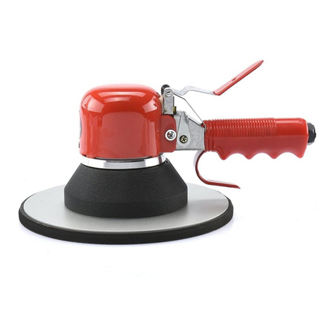
Model5558A
6"
DualAction Sander, Serial Number
to which thisdeclaration relates isinconformity
with
thefollowingstandard(s) orother normativedocument(s)
EN792 (Draft), EN292 Parts
1
&
2,
IS08662 Parts
1
&
8, Pneurop PN8NTC1
followingthe provisionsof
89139ZEECas amended
by
91/368/EEC
&
93144fEEC Directives
&
fAL
G a
.
Seebeck (President)
Page
No
3
