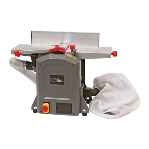
SIP 01557 User manual

8”x 8” Planer Thicknesser
10”x 10” Planer Thicknesser
Please read and fully understand the instructions in this
manual before operation.
Keep this manual safe for future reference.
01557
01558

2
CONTENTS
Pg.2 Manual Contents
Pg.3 Product Specification
Pg.4 Safety Symbols
Pg.4 Safety Instructions
Pg.7 Electrical Connection
Pg.8 Box Contents & Accessories
Pg.8 Guarantee
Pg.9 Getting to know your Planer Thicknesser
Pg.10 Assembly
Pg.14 Operating Instructions
Pg.16 Wiring Diagram
Pg.17 Maintenance
Pg.19 Troubleshooting
Pg.20 01557 8" Planer Thicknesser Exploded View
Pg.21 01557 8" Planer Thicknesser Part List
Pg.25 01558 10" Planer Thicknesser Exploded View
Pg.27 01558 10" Planer Thicknesser Part List
Pg.30 UK Declaration of Conformity
Pg.31 EU Declaration of Conformity

3
PRODUCT SPECIFICATION
PLANING 01557 8 x 8 Planer /
Thicknesser
01558 10 x 10 Planer /
Thicknesser
Planer Width 204mm 252mm
Planer Length 740mm 920mm
Max Cutting Depth 2.5mm 2.5mm
Fence Tilt 90 - 135o90 - 135o
Table Width 355mm 445mm
THICKNESSING
Timber Size Thicknessing - Min / Max 5 - 120mm 5 - 120mm
Max Timber Width 204mm 252mm
Max Depth Cut 2.0mm 2.0mm
Feed Speed 6.4mtrs / min 6.4mtrs / min
DIMENSIONS & SPECIFICATION
Motor 230v 1500w 230v 1500w
Cutter Block Speed 9000rpm 9000rpm
Dust Extraction Outlet - ID 55mm 55mm
Dust Extraction Outlet - OD 62mm 62mm
Dust Extraction Adaptor - ID 63mm 63mm
Dust Extraction Adaptor - OD 68mm 68mm
Noise Level 105dB(A) 105dB(A)
Weight—GW / NW 28 / 24kg 31 / 27kg
Packaged Dimensions L x W x H 850 x 430 x 460mm 1030 x 430 x 520mm

Danger / Caution: Indicates risk of personal injury and/or the
possibility of damage.
Warning: Risk of electrical injury or damage.
Note: Supplementary information.
SAFETY SYMBOLS & SAFETY INSTRUCTIONS
SAFETY INSTRUCTIONS
WARNING: When using electric tools, basic safety precautions should always be followed to
reduce the risk of fire, electric shock and personal injury, including the following.
Read all these instructions before attempting to operate this product and save these instructions.
(1) Keep work area clear
-Cluttered area and benches invite injuries.
(2) Consider work area environment
-Don’t expose electric tools to rain.
-Do not use electric tools in damp or wet locations.
-Keep work area well lit.
-In particular, no inflammable liquids or gases must be present.
(3) Guard against electric shock
-Avoid body contact with earthed or grounded surface.
(4) Keep children and other persons away
-Don’t let especially children, persons not involved in the work touch the tool or extension cord and
keep them away from the work area.
(5) Store idle tools
-When not in use, tools should be stored in a try locked up place, out of reach of children.
(6) Don’t force the tool
-It will do the job better and safer at the rate for when it was intended.
(7) Use the right tool
-Don’t force small tools to do the job of a heavy-duty tool.
-Don’t use tools for purposes not intended: for example, don’t use circular saws to cut tree limbs or logs.
(8) Dress properly
-Don’t wear loose clothing or jewelry. They can be caught in moving parts.
-Rubber gloves and non-skid footwear are recommended when working outdoors.
-Wear protective hair covering to contain long hair.
(9) Use protective equipment
-Use safety glasses.
-Use face or dust mask if cutting operations create dust.
4

5
SAFETY INSTRUCTIONS Cont.
(10) Don't abuse cables
-Never carry a tool by its cable , or "yank" the cable to disconnect from a socket.
-Keep cable away from heat, oil and sharp edges.
-Do not abuse the lead.
(11) Don't overreach
(12) Keep proper footing and balance at all times.
(13) Maintain tools with care.
(14) Keep cutting tools sharp and clean for better and safer performance.
(15) When not in use, before servicing and when changing accessories such as blades, bits, cutters,
disconnect tools from the power supply.
(16) Remove adjusting wrenches
- Get into the habit of removing wrenches, spanners etc from the planer / thicknesser before switching it
on.
(17) Avoid unintentional starting
(18) Ensure switch is in “off” position when plugging in.
(19) Use outdoor extension leads
(20) When the tool is used outdoors, use only extension cords intended for outdoor use and so marked.
(21) Stay alert
(22) Watch what you are doing, use common sense and do not operate the tool when you are tired.
(23) Check damaged parts
(24) Before further use of tool, it should be carefully checked to determine that it will operate properly and
perform it’s intended function.
(25) Check for alignment of moving parts, binding of moving parts, mounting and any other conditions that
may affect it’s operation.
(26) A guard or other part that is damaged should be properly repaired or replaced by an authorized
service centre unless otherwise indicated in this instruction manual.
(27) Have defective switches replaced by an authorized service centre.
(28) Do not use the tool if the switch does not turn it on and off.
(29) Warning
(30) The use of any accessory or attachment other than one recommended in this instruction manual may
present a risk of personal injury.
(31) Have your tool repaired by a qualified person
(32) This electric tool complies with the relevant safety rules. Qualified persons using original spare parts
should only carry out repairs. Otherwise this may result in considerable danger to the user.
(33) Never use the machine without the appropriate guard in place and correctly adjusted.
(34) Do not use knives, which are blunt as this increases the danger of kickback.
(35) Any portion of the cutter block not being used for planning shall be guarded.
(36) When planning short workpieces, a push-stick should be used.
(37) When planning narrow workpieces additional measures. Such as of horizontal pressure devices and
spring-loaded guards, may be necessary to ensure safe working.
(38) Do not use the tool cut rebate.
(39) The effectiveness of the device for the prevention of kickback and the feed spindle should be
regularly inspected to ensure safe operation.

6
(40) Tools equipped with chip collection and extractor hoods shall be connected to the dust and chip-
collecting device.
(41) Use the tool only for wood or similar materials.
When the blade is abraded 95%, you must change it to the new one, which must meet EN / UK standards.
(43) Two persons are required for moving round the workshop due to its heavy weight.
(44) The machine should be fixed on the floor by screws when operating.
SAFETY INSTRUCTIONS Cont.
Regularly check that blades and lock bars are locked tight in cutter block.
Max. allowable blade projection over cutter block 1.0mm/0.004 inch +10%.
Never remove any of the machines safety guards other than for servicing and repair work.
Keep guards operational at all times.
Set and secure safety guards in position before operating machine.
This machine must be safety earthed. The yellow/green (green) lead is the earth conductor.
Regularly check anti-kickback fingers for proper operation.
Always wear eye protection.
Rebating, tenoning, moulding and recessing may not be undertaken without the use of special guards.
Never make jointing or planning cut deeper than 2 mm
USER RESPONSIBILITY
This machine will perform in conformity with the description contained in this manual when installed,
operated, maintained and repaired in accordance with the instructions provided.
This machine must be checked periodically. Defective equipment (including power cable) should not be
used. Parts that are broken, missing, plainly worn, distorted or contaminated, should be replaced
immediately. Should such repair or replacement become necessary, it is recommended that such repairs
be carried out by qualified persons.
This machine or any of its parts should not be altered or changed or changed from standard
specifications. The user of this machine shall have the sole responsibility for any malfunction which
results from improper use or unauthorized modification from standard specification, Faulty
maintenance, damage or improper repair.

7
Warning! It is the responsibility of the owner and the operator to read, understand and
comply with the following:
You must check all electrical products, before use, to ensure that they are safe.
You must inspect power cables, plugs, sockets and any other connectors for wear or damage.
You must ensure that the risk of electric shock is minimised by the installation of appro-priate safety
devices; A residual current circuit Breaker (RCCB) should be incorporated in the main distribution board.
We also recommend that a residual current device (RCD) is used. It is particularly important to use an
RCD with portable products that are plugged into a supply which is not protected by an RCCB. If in any
doubt consult a qualified electrician.
Connecting to the power supply:
The 01557 / 01558 Planer Thicknesser are fitted with a standard 230V ~ 13 amp type plug. Before every
usage, inspect the mains lead and plug to ensure that neither are damaged. If any damage is visible
have the welder inspected / repaired by a suitably qualified person. If it is necessary to replace the
plug a heavy duty impact resistant plug would be preferable.
The wires for the plug are coloured in the following way:
Earth
Neutral
Yellow /
green Blue
Brown Live
As the colours of the wires may not correspond with the markings in your plug, proceed as
follows:
The wire which is coloured blue, must be connected to the terminal marked with N or coloured
black (or blue).
The wire which is coloured brown, must be connected to the terminal, which is marked L or
coloured red (or brown).
The wire which is coloured yellow / green should be connected to the terminal which is coloured
the same or marked
Always secure the wires in the plug terminal carefully and tightly. Secure the cable in the cord grip
carefully.
ELECTRICAL CONNECTION

A. Planer and Thicknesser
B. Dust chute, Extraction outlet, Cutter Setting Gauge, Tools (x3), Handle, Push-stick, Push pad (x2),
Rubber feet (x4), Screws (x4) and Washers (x4)
C. Angle fence and Cutter guard system
D. Manual
Check for shipping damage. If damage has occurred, a claim must be filed with carrier.
Check contents is correct. Immediately report missing parts to dealer.
The machine is shipped complete in one carton. Additional parts which need to be fastened to machine should
be located and accounted for before assembling.
A
B
DD
C
B
8
CONTENTS & ACCESSORIES
GUARANTEE
This SIP Planer Thicknessers are covered by a 12 month parts and labour warranty covering failure due to
manufacturers defects. This does not cover failure due to misuse or operating the product outside the scope of
this manual - any claims deemed to be outside the scope of the warranty may be subject to charges, including,
but not limited to parts, labour and carriage costs, failure to regularly clean your planer thicknesser will shorten
its working life and reduce performance.

GETTING TO KNOW YOUR PLANER THICKNESSER
2
1312
14
118 9
6
5
4 3 1
7
10
12 13
15
Item No Description Item No Description
1Overload 9Planing Blade Guard Assembly
2NVR On / Off 10 Adjustor
3Inter– Lock Switch Tongue 11 Adjustment Screw
4M6 Hand Knob 12 Thicknessing Crank Handle
5Extraction Chute with Expander 13 Planing Cut Adjustment Knob
6Guard Pivot Bolt 14 Infeed Table
7Outfeed Table 15 Planing Depth Gauge
8Adjustable Fence
9

The planers weigh approximately 24 & 28Kgs respectively, when completely assembled.
The planer must be installed in a place with ample lighting and correct power supply. To install planter:
1. Make sure there is plenty of room for moving the work-piece through the entire cut. There must be
enough room that neither the operators nor the bystanders will have to stand in line with the wood while
using the tool.
2. Planer should be installed on a workbench using bolts, Locking Nuts and Hex nuts.
3. The planer must be bolted to a firm, level surface.
4. Make sure the planer does not rock and the tables are level.
ASSEMBLY
Alternatively, mount the planer on a strong piece of plywood of at least 20mm in thickness, with length
550mm and width 400mm minimum. The plywood platform, with planer mounted, is then clamped firmly to a
workbench when required.
550mm
400mm
Fig.1
1. Attaching the Angle Fence
Insert the screws (C) into the holes in the Fence (8), then
tighten.
Loosen the lock handle (E) to adjust the fence angle.
Fig.1
8
C
E
10
Fig.1

3. Attaching the Dust Collector Chute.
IMPORTANT: Please note that the Dust Chute must
always be in place, the machine will not operate if is
removed.
11
ASSEMBLY Cont.
2. Attaching The Table Adjustment Handle
Slide the table handle on to the shaft.
Fig.2
Fig.3
Fig.2
Fig.3
A. For Planing
1. Lower the Thicknesser Table as far as possible by turning the table adjustment handle fully anticlockwise.
2. Pull out the two Inter-Locking Tongue keys (3) and manoeuvre the Chute (5) into the space beneath the
table. Ensure both Locking keys are pushed firmly into the slots in the table.
Positioning the Dust Collector Chute .
12
5
3

B.For Thicknessing
1. Remove the Angle Fence (8).
2. Push the Cutter Guard (9) out of its holder so that the Chute (5) may be attached to the table.
3. Ensure both Inter-Locking Tongue keys (3) are pushed firmly into the slots in the table.
12
ASSEMBLY Cont.
Warning: Risk of electrical injury or damage.
Do not bypass the inter-locking safety switches
Note: The Planer Thicknesser will not run without the extractor chute fitted correctly
The machine is fitted with 2 inter-locking safety switches.
5
3
9

4. Attaching the Cutter Guard System
1. Place the pivot screw (X) in the position. Use this to lock the guard arm.
2. Screw in the Angle Adjusting hand-wheel (Y).
3. Use the two Thumb screws (Z) for fine angle adjustment.
X
Y
Z
5.Attaching Rubber feet
1. Secure the four rubber feet to the bottom side of the equipment using the Allen screws and washers
supplied.
13
ASSEMBLY Cont.

Place the cutter setting tool, as shown in the picture, on the knife block. Make sure that the knife touches both
sides of the blade adjustment block.
A
Make sure that the switch is in off position before adjusting the cutting depth, replacing or adjusting the
blades. Make sure the blade screws are securely tightened and the table is free of nails, screws and staples
etc., before use.
Loosen the lock handle A to adjust the fence angle.
14
OPERATING INSTRUCTIONS
SETTING THE ANGLE FENCE
SETTING THE CUTTER BLADE
1,1 mm
Cutter Setting Tool
DUST EXTRACTION REQUIRED!

15
PLANING
1. The cutting depth is set by the knob (13) & gauge (15) at the infeed table. We recommend a depth of cut of
no more than 1mm and no less than 0.5mm. The maximum depth of cut is 2mm.
2. Ensure the fence (8) is at the correct angle. For normal planing, this would be 90 degrees.
3. Slide the cutter guard (9) out of the way and place the workpiece on the table so that it rests snugly against
the fence, with the lead edge a short distance from the cutter, noting that direction of feed is right to left,
looking from the front of the machine.
4. Slide the cutter guard up to lightly touch the workpiece, thereby completely covering any exposed cutter.
Ensure the guard is as low as possible and the Cutter Guard Lock Knob is tightened.
5. Press the green ON button and allow the machine to come up to full speed.
6. Applying firm downwards pressure, and keeping the workpiece against the fence, proceed to feed the work
over the cutter. Do not feed too quickly.
7. Press the green Off button.
IMPORTANT: ALWAYS use the push stick and the push pad/s as shown in the picture. Fig.B
THICKNESSING
1. Lower the Thicknessing table using handle (12) sufficiently for the workpiece to be inserted beneath the cutter
blade, ensuring the blade is at 6 o’clock. Work enters from the left and exits at the right of the machine.
2. Raise the table until there is slight resistance. The work just touches the blade.
3. Withdraw the workpiece, then wind the table upwards - turn clockwise, using the Raise/Lower Handle (12),
(see Fig.C) to the appropriate cutting depth, noting that one turn is equivalent to 3mm. Do not exceed 2mm
depth of cut as this could cause kickback, and/or damage to the components or overheating of the motor.
4. It is advisable when working with rough or warped wood to make very small depths of cut to begin with - 1mm
should be sufficient, or 1/4 of a turn of the handle.
5. Support the workpiece at the desired height, so that it is horizontal and feed it into the cutter, from the left
hand side of the machine. The rollers will automatically feed the work past the kick-back pawls and into the
cutter blade. Ensure it is well supported at the outlet side.
IMPORTANT:DO NOT remove chips or shavings from the table until the machine has stopped
completely and is isolated from the mains supply.
OPERATING INSTRUCTIONS Cont.
Fig.A
13
15
Fig. B

12
Circuit Breaker Safety Switch
WIRING DIAGRAM
OPERATING INSTRUCTIONS Cont.
General Information:
For best results try to plane / thickness following the grain. This will reduce the amount of further finishing
required.
For rough sawn timber requiring finishing on all 4 sides:-
Set the machine for planing.
Identify the flattest of the two wider faces on the timber.
Pass that side over the planer as many times as necessary until a flat and smooth finish is achieved.
Hold the planed side firmly against the guide fence (set at 90 degrees to the bed) and pass the narrow side over
the planer as many times as necessary until a flat and smooth finish is achieved.
You should now have two planed sides at 90 degrees to each other.
Set the machine up for thicknessing.
Pass the timber through the thicknesser with the wider already planed side facing down against the bed.
Continue until the desired thickness for the timber is reached.
Finally, pass the timber through the thicknesser with the planed narrow side facing down against the bed.
Continue until the desired thickness for the timber is reached.
Fig.C
16

Prior to doing any maintenance work, always pull out the mains plug.
Machine care
The planer thicknesser is designed with a low maintenance requirement. The bearings are greased for life.
After approximately 10 hours of operation we recommend to lubricate the following parts:
-Bearings of the feed-in and feed-out rollers.
-Bearings of pulley and gear wheel of the belt.
-Treat threaded spindles for the height adjustment of the thicknessing table with dry lubricant only!
-The table surface and feed-in / feed-out rollers should always be kept clean of resin.
-Dirty feed-in rollers and feed-out rollers have to be cleaned.
In order to prevent the motor from overheating, regularly check that no dust has accumulated on the
ventilation apertures of the motor.
After a prolonged period of operation, users are recommended to have the machine checked by an
authorized customer service shop.
Tool care
The cutter head, clamping devices, knife supports and knives used on the machine must be freed from
resin regularly as a clean tool improves the cutting quality. This can be done by soaking the
clamping devices, knife supports and reversible knives for 24 hours in paraffin, white spirit or
commercially available resin remover.
Tools made of aluminium may only be depurated with cleaning agents, which do not corrode this kind of
material.
Do not use solvents to clean the machine as this could damage plastic components.
17
MAINTENANCE
Cutter Blade Removal
Cutter blades will require sharpening or replacing. Care should be taken at all times when
handling them, they are very sharp, even when appearing to be dull.
Blades must always be fitted as a pair, and must be of the same type, only fit blades
recommended by SIP Industrial Products Ltd.
First, ensure the machine is switched OFF and isolated from the mains supply.
1. Turn the cutter height adjuster so that it registers zero. i.e. turn the knob clockwise so that the depth of
cut, registered on the scale, is zero.
2. Remove the Angle Fence.
3. Raise the Cutter Guard arm.
4. Turn the cutter block to reveal the four hex. socket head screws securing the cutter blade, then carefully
remove them. Fig. D
5. Turn the cutter block by 180 degrees and repeat the process.
ALWAYS hone/replace cutter blades as a pair.
6. Replace in reverse order, and, using a straight edge, ensure the cutting edges are level and in line with
the table when they are at 12 o’clock. Tighten the securing screws taking care not to over-tighten or
damage the hex. sockets.

NOTE: It is recommended that sharpening is done professionally, using a jig, as blades must be
sharpened as a pair to ensure they are correctly balanced. This avoids the possibility of vibration due to
unbalanced cutters rotating at speed.
Drive Belt Replacement
1. Remove the front cover - 3 nuts.
2. Remove the worn or broken drive belt.
3. Place the replacement drive belt over the small belt wheel.
4. Position part of the drive belt over the large belt wheel.
5. Rotate the large belt wheel by hand in a clockwise direction whilst guiding the belt on to the belt
wheel.
18
MAINTENANCE Cont.
Fig. D

TROUBLESHOOTING
Problem Cause Remedy
Machine does not start Blown Fuse Replace Fuse
Loose switch terminal Inspect back of switch
Faulty switch Replace switch
Guard not fitted Re-fit the plastic guard
ensuring it connects with the
interlock switch
Only starts when Green
button is held down
Faulty switch Replace switch
Machine runs intermittently Worn carbon brushes in motor Replace motor brushes
Motor running but
cutterblock is not rotating
Broken or stretched drive belt Replace drive belt
Motor slows down during
the cut
Depth of cut is too great Take a smaller cut
Dust & Chip collector hood
is blocked
Clear the blockage and
ensure the extractor is
functioning correctly
Planing knives are blunt Replace or sharpen knives
Excess Vibration Planing knives out of balance Reset the height of the knives
19

EXPLODED VIEW
01557 8" PLANER THICKNESSER
20
This manual suits for next models
1
Table of contents
Other SIP Planer manuals
Popular Planer manuals by other brands

laguna
laguna SHEARTEC II PX-22 owner's manual

Triton
Triton TCMPL Operating/safety instructions

Craftsman
Craftsman 351.217480 Operator's manual

Bosch
Bosch 3365 - 3-1/4 Planer w/ Parallel Guide Fence Operating/safety instructions

DeWalt
DeWalt DW735 instruction manual

Bosch
Bosch GHO Professional 16-82 Original instructions