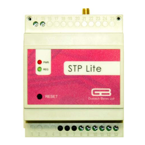
SIPOS SEVEN 2SP781 User manual

Issue 10.18 Y070.477/EN
Subject to changes without notice!
Part-turn gearboxes
2SP78.
Supplement to
Operation instructions
SIPOS SEVEN

Supplement to operation instructions SIPOS SEVEN
Part-turn gearboxes 2SP78.
Page 2 Y070.477/EN
Contents
Contents
Contents
1 General information ........................... 3
1.1 Notes to the operation instructions ....... 3
1.2 Safety instructions: Used symbols
and their meanings ............................... 3
2 Mount part-turn gearbox
to valve................................................ 4
2.1 Mount via coupling ............................... 4
2.2 Mount with base and lever ................... 5
2.2.1 Change base position .......................... 5
2.2.2 Mount part-turn gearbox ....................... 5
2.2.3 Mount swing lever with cone
clamping element to gearbox .............. 6
2.2.4 Notes on mounting damper rods .......... 7
2.3 Mount actuator to part-turn gearbox ..... 8
3 Maintenance ....................................... 8
3.1 General remarks ................................... 8
3.2 Service ................................................. 8

Y070.477/EN Page 3
Supplement to operation instructions SIPOS SEVEN
Part-turn gearboxes 2SP78.
1
General information
1 General information
1 General information
1.1 Notes to the operation instructions
These supplementary instructions describe the assembly of the part-turn gearbox and are complete
only in combination with the main operation instructions of the respective SEVEN PROFITRON or
HiMod actuators.
The safety information contained in the main operation instructions must be heeded at all times
when working with the actuators.
For the sake of clarity, not all details of all versions of the product are described in these operation
instructions, nor can they cover all conceivable cases regarding installation, operation and mainte-
nance. For this reason, the operation instructions only contain instructions for qualied personnel
that are necessary when the equipment is used for the purpose for which it is intended or in indus-
trial applications.
In case of any questions, and especially where detailed product information is not available, contact
the SIPOS Aktorik sales representative in charge. Always state the type designation and the serial
number of the respective actuator (see name plate).
1.2 Safety instructions: Used symbols and their meanings
The following symbols, which have different meanings, are used in the operation instructions.
Non-observance of safety instructions may lead to serious injuries or damage.
Warning marks activities which, if not carried out correctly, can affect the safety of persons or
property.
Notice marks activities which have major inuence on the correct operation. Non-observance of
these notes may lead to consequential damage.

Supplement to operation instructions SIPOS SEVEN
Part-turn gearboxes 2SP78.
Page 4 Y070.477/EN
2 Part-turn gearbox assembly
Mounting via coupling
2
Part-turn gearbox assembly
2 Mount part-turn gearbox to valve
The part-turn gearbox is either mounted to the valve via
■a coupling, refer to following chapter „2.1 Mount via coupling“
or via
■a swing lever; refer to chapter „2.2 Mount with base and lever“.
■The work below must only be performed by expert personnel!
■The part-turn gearboxes can be mounted in any position.
■After working on the unit, touch up damage to paint to avoid corrosion on the device.
2.1 Mount via coupling
Depending on the order, the couplings for valves (g.1, item 2) will be supplied unbored or e.g. with
bore and keyway, square bore or bore with two ats.
Prior to mounting the part-turn gearbox to the valve, unbored couplings must be machined (item 4)
to match the valve shaft (item 5).
Mount valve and actuator in the same end position:
■For buttery valves – end position CLOSED.
■For ball valves – end position OPEN.
Procedure
1. Clean contact surfaces at part-turn gearbox-
es (g. 1, item 1) and valve (item 6).
2. Slightly grease valve shaft (item 5) and
splines of the coupling (item 2).
3. Fit coupling (item 4) onto valve shaft (item 5)
and secure against axial shifting with grub
screw (item 3) while heeding dimensions x, y
(refer to g. 2 and table below).
4. Place part-turn gearbox (item 1) onto valve
(item 6):
– Make sure the anges are centered and
ush against the actuator.
– If the ange holes do not match the
threaded holes, shift part-turn gearbox by
one spline on the coupling if required.
5. Fasten part-turn gearbox with screws
(item 7):
–We recommend gluing the screws with
liquid thread sealing material to avoid
contact corrosion.
–Tighten screws crosswise with the
required tightening torque (refer to table
below).
Fig. 1: Assembly with coupling
Fig. 2: Mounting position of the coupling

Y070.477/EN Page 5
Supplement to operation instructions SIPOS SEVEN
Part-turn gearboxes 2SP78.
2
Part-turn gearbox assembly
2 Part-turn gearbox assembly
Mounting with base and lever
2.2.1 Change base position
Depending on the place of installation, modify-
ing the position of the part-turn gearbox base
might be required.
1. If the base has been pre-assembled to the
part-turn gearbox, unscrew the four screws
(g., item 1).
2. Rotate base (item 2) as required, see arrow
in illustration.
3. Slightly screw in four screws and tighten
them crosswise.
Heed tightening torque, refer to table below:
Tightening torque for connection at part-
turn gearbox base
Part-turn gearbox Screw Torque
2SP781 / 2SP782 /
2SP783 M10 41 Nm
2SP784 / 2SP785 M16 175 Nm
2.2.2 Mount part-turn gearbox
The mounting support of the base muss be
solid, rigid and low in vibration.
Procedure
1. Align mounting positions so that the motion
planes of the damper rod (item 1) and the
valve levers (item 2) are in parallel.
The permissible angle deviation amounts to
–in the opposite direction of the swing
lever (item 2): max. 10°,
–in the same direction as the swing lever:
max. 3°.
2. Clean contact surfaces of base ange.
3. Tighten part-turn gearbox base with four
screws (at least strength class 8.8).
Fig.: Change base position
Fig.: Mounting position Rod to swing lever
Dimensions for mounting position of the coupling
and tightening torques for screws of different strength classes
Flange Dimensions [mm] Screws Tightening torque TA [Nm]
strength classes
xmax. ymax. Qty x wt. A2-70/A4-70 A2-80/A4-80
F07 6 3 4 x M8 15 21
F10 1 3 4 x M10 30 41
F12 1 3 4 x M12 53 71
F14 1 4 4 x M16 131 175
F16 1 4 4 x M20 256 341
2.2 Mount with base and lever
Prior to mounting, make sure the space available is sufcient. Lever and damper rods must move
in parallel and the swivel range must be free of obstacles.

Supplement to operation instructions SIPOS SEVEN
Part-turn gearboxes 2SP78.
Page 6 Y070.477/EN
2 Part-turn gearbox assembly
Mounting with base and lever
2
Part-turn gearbox assembly
2.2.3 Mount swing lever with cone clamping element to gearbox
Function of cone clamping element
Cone clamping elements are internal clamping connections for backlash-free fastening of hubs on
shafts. Torques are transmitted from the shaft via the cone clamping element to the hub.
The cone clamping element consists of a slotted
outer ring (g., item 1) with inside cone and a
slotted inner ring (item 2) with outside cone as
well as several clamping screws (item 3).
Fastening the clamping screws will t the outer
ring to the outer ring. The tightening torque of
the clamping screws, the cone angle as well as
the friction coefcients of the screws and conical
surfaces determine the intensity of radial clamp-
ing forces generated by the conical surface. The
radial clamping forces press the outer ring into
the hub bore and the inner ring onto the shaft,
resulting in friction-based connection at the
respective contact surfaces.
Thus, torque can be transmitted between shaft
and hub.
Fig.: Cross section of cone clamping
element
1. Carefully clean contact surfaces at both
shaft and swing lever.
2. Apply thin layer of oil to cone clamping
element.
Neither use oil with molybdenum disul-
de or extreme pressure additives nor
grease!
3. Fit cone clamping element (g. 1, item 1)
into the swing lever (item 2) (a) and slide
onto the shaft (item 3) (b).
4. Align swing lever (g. 2, item 1) and heed
distance between cone clamping element
(item 2) and shaft (item 3).
5. Tighten clamping screws as follows, refer to
g. 3, sequence shown in A, B and C:
–First use torque spanner to tighten all
clamping screws crosswise at half the
tightening torque (see table), refer to A
in illustration 3 (sequence 1 – 6).
–Tighten all clamping screws clockwise
one after the other at half the tighten-
ing torque (see table), refer to B in g. 3,
(sequence 1 – 6).
–After that, tightening all clamping screw
clockwise one after the other and
several times at full tightening torque,
refer to C in g. 3.
Fig. 1: Place cone clamping element and
swing lever
Fig. 2: Align swing lever and cone clamping
element
Mount swing lever with cone clamping element

Y070.477/EN Page 7
Supplement to operation instructions SIPOS SEVEN
Part-turn gearboxes 2SP78.
2
Part-turn gearbox assembly
2 Part-turn gearbox assembly
Mounting with base and lever
2.2.4 Notes on mounting damper rods
When setting the length of the damper
rods, make sure that the angle α min. or
α max. is not fallen short of or exceed-
ed (refer to g.). Otherwise, excessive
forces, which might damage the actua-
tor or the part-turn gearbox, may occur.
Permissible limits are
■Angle α
– αmin. = 30°,
– αmax. = 150°.
■Angle β (refer to g.) must be
indicated by the valve manufacturer.
Suitable damper rods (ball joints with lever) or ball joints are subject to separate order from
SIPOS Aktorik.
One of the supplied ball joints has a right-hand thread, the other one a left-hand thread.
Fig.: Deection angle
Fig. 3: Tighten cone clamping element
■The tightening procedure is not complete until no screw turns after fastening at full tightening
torque.
■Only replace missing or damaged clamping screws by identical screws of grade 12.9!

Supplement to operation instructions SIPOS SEVEN
Part-turn gearboxes 2SP78.
Page 8 Y070.477/EN
3 Maintenance
3
Maintenance
1. Clean contact surfaces at actuator and part-
turn gearbox.
2. Screw part-turn gearbox to actuator:
Fasten screws with washers (g.1, item 1)
evenly crosswise.
Heed tightening torque, refer to table below:
Tightening torque for connection
between actuator and part-turn gearbox
Part-turn gearbox Screw Torque
2SP781 / 2SP782 M10 41 Nm
2SP783 M10 30 Nm
2SP784 / 2SP785 M16 175 Nm Fig.: Mount actuator to part-turn gearbox
3 Maintenance
3.1 General remarks
After commissioning, check part-turn actuator for damage to paint nish. Thoroughly touch up
damaged spots to prevent damage by corrosion.
The part-turn actuator requires very little maintenance. To ensure permanent operability, we recom-
mend the following measures:
■Approximately six months after commissioning and then once a year check xing screws between
actuator, part-turn gearbox and valve for tightness. If required, tighten the screws with the torques
corresponding to the strength class of the screws used.
■Every 2 years, check each actuator and gearbox visually for oil leakage.
■Every 8 years, submit the actuator and the mounted gearbox to a detailed functional test. Record
results for later reference.
3.2 Service
SIPOS Aktorik provides comprehensive services such as assembly, commissioning, mainte-
nance and revision as well as inspection of actuators. For contact addresses, please visit us at
www.sipos.de.
Issue 10.18 Y070.477/EN
Subject to changes without notice!
© SIPOS Aktorik GmbH
Im Erlet 2 • D-90518 Altdorf
www.sipos.de
2.3 Mount actuator to part-turn gearbox
This manual suits for next models
5
Table of contents
Other SIPOS Controllers manuals
