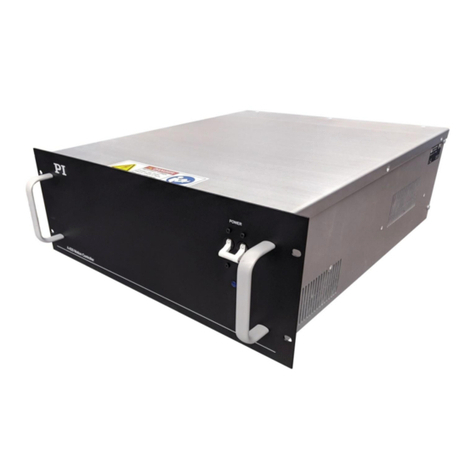
PI E-727 User manual

User Manual
E727T0005, valid for E-727
BRO, 2019-06-28
Physik Instrumente (PI) GmbH & Co. KG, Auf der Roemerstrasse 1, 76228 Karlsruhe, Germany Page 2 / 240
Contents
About this Document 8
Symbols and Typographic Conventions ............................................................................................... 8
Other Applicable Documents............................................................................................................... 9
Downloading Manuals ....................................................................................................................... 10
Safety 11
Intended Use...................................................................................................................................... 11
General Safety Instructions................................................................................................................ 11
Organizational Measures ................................................................................................................... 12
Personnel Qualification...................................................................................................................... 12
Product Description 13
Model Overview................................................................................................................................. 13
Product View...................................................................................................................................... 14
Scope of Delivery................................................................................................................................ 19
Accessories......................................................................................................................................... 19
Functional Principles .......................................................................................................................... 20
Block Diagrams .......................................................................................................................................20
Axes, Channels, Functional Elements .....................................................................................................22
Important Components of the Firmware ............................................................................................... 26
Input Signal Processing........................................................................................................................... 27
Control Value Generation....................................................................................................................... 30
Output Generation .................................................................................................................................34
Control Details.................................................................................................................................... 35
Slew Rate Limitation ...............................................................................................................................35
Control Algorithms ................................................................................................................................. 35
Feedforward ........................................................................................................................................... 37
Notch Filters ...........................................................................................................................................37
ID Chip Detection ............................................................................................................................... 39
Overtemp Protection ......................................................................................................................... 39
Overview of PC Software ................................................................................................................... 40
Installation 43
General Notes on Installation ............................................................................................................ 43
Installing the PC Software .................................................................................................................. 43
Performing the Initial Installation...........................................................................................................43
Installing Updates ................................................................................................................................... 46
Ensuring Ventilation........................................................................................................................... 47
Connecting the E-727 to the Protective Earth Conductor ................................................................. 48

User Manual
E727T0005, valid for E-727
BRO, 2019-06-28
Physik Instrumente (PI) GmbH & Co. KG, Auf der Roemerstrasse 1, 76228 Karlsruhe, Germany Page 3 / 240
Start-Up 49
General Notes on Start-Up................................................................................................................. 49
Starting the System in PIMikroMove ................................................................................................. 51
Creating Backup Files for Controller Parameters............................................................................... 53
Executing Test Motions in Open-Loop Operation.............................................................................. 54
Operation 56
Communication.................................................................................................................................. 56
PC Interfaces...........................................................................................................................................56
Additional Interfaces ..............................................................................................................................56
Communication via the TCP/IP Interface ............................................................................................... 56
Communication via the RS-232 Interface ...............................................................................................61
Communication via the USB Interface....................................................................................................62
AutoZero Procedure........................................................................................................................... 62
Objective and Prerequisites of AutoZero ............................................................................................... 63
Settings Changed by AutoZero ............................................................................................................... 63
Starting AutoZero via Command Entry................................................................................................... 63
Starting AutoZero in PIMikroMove......................................................................................................... 64
Starting AutoZero via EtherCAT Master ................................................................................................. 65
Special Function: Sensor Autoscaling .....................................................................................................65
Data Recording................................................................................................................................... 65
How to Use the Data Recorder............................................................................................................... 65
Data-Recorder Related Commands and Parameters.............................................................................. 67
Using Digital Input.............................................................................................................................. 68
Configuring Trigger Output ................................................................................................................ 69
Overview of Trigger Options, Commands and Parameters .................................................................... 69
Example—"Position Distance" Trigger Mode .........................................................................................71
Example—"On Target" Trigger Mode..................................................................................................... 80
Example—"MinMax Threshold" Trigger Mode ...................................................................................... 81
Example—"Generator Level Trigger" Mode ........................................................................................... 82
Example—"Generator Pulse Trigger" Mode........................................................................................... 83
Example—Polarity Setting ...................................................................................................................... 84
Examples—"TriggerOutAND" and "TriggerOutOR" Modes ....................................................................84
Using the Analog Input....................................................................................................................... 85
How to Work with the Analog Input - Overview .................................................................................... 85
Scaling the Analog Input .........................................................................................................................87
Use as Control Value Generation Source ............................................................................................... 90
Use as External Sensor Input .................................................................................................................. 91
Deactivation of Unused Analog Input Lines............................................................................................92
Analog-Input-Related Commands and Parameters................................................................................ 92
Using the Analog Output.................................................................................................................... 94
How to Work with the Analog Output - Overview ................................................................................. 94
Use as Position Monitor .........................................................................................................................95
Use as Control Signal .............................................................................................................................. 96
Analog-Output-Related Commands and Parameters .............................................................................97
Wave Generator................................................................................................................................. 99
How to Work with the Wave Generator................................................................................................. 99

User Manual
E727T0005, valid for E-727
BRO, 2019-06-28
Physik Instrumente (PI) GmbH & Co. KG, Auf der Roemerstrasse 1, 76228 Karlsruhe, Germany Page 4 / 240
Wave Generator Examples ................................................................................................................... 104
Wave-Generator-Related Commands and Parameters........................................................................112
Dynamic Digital Linearization (DDL)................................................................................................. 114
Working Principle .................................................................................................................................114
How to Activate the DDL License..........................................................................................................117
How to work with the DDL ...................................................................................................................118
DDL-Related Commands and Parameters ............................................................................................ 120
Controller Macros ............................................................................................................................ 121
Commands for Macros ......................................................................................................................... 121
Working with Macros ...........................................................................................................................123
Variables .......................................................................................................................................... 130
Adjustment Procedures 131
ID-Chip Support / Stage Replacement ............................................................................................. 131
"Simple" Replacement..........................................................................................................................131
Upgrade or Repair of Stages.................................................................................................................132
Replacement of Tip/Tilt Platforms with Differential Drive ...................................................................132
Servo-Controller Dynamic Tuning .................................................................................................... 134
Parameters to be Modified ..................................................................................................................134
General Notes on Servo-Controller Dynamic Tuning............................................................................134
Adjusting the Notch Filter(s) in Open-Loop Operation.........................................................................136
Checking and Optimizing the Servo-Control Parameters .....................................................................140
SPI Interface 144
Definition of Terms .......................................................................................................................... 144
Overview .......................................................................................................................................... 144
Configuration Parameters................................................................................................................ 145
Configuring the Usage of Received Data ..............................................................................................145
Configuring the Limits for Position Scaling ...........................................................................................145
Data Packet Definition ..................................................................................................................... 146
Data Frame ...........................................................................................................................................146
CRC-16 Generation ...............................................................................................................................146
Transport Layer ................................................................................................................................ 147
Data Segment 1 ....................................................................................................................................147
Data Segment 2 ....................................................................................................................................147
Connection Lost ....................................................................................................................................150
Transport Layer Flow Charts ............................................................................................................ 150
Nomenclature.......................................................................................................................................150
Sender Flow Charts...............................................................................................................................151
Receiver Flow Charts ............................................................................................................................153
Application Layer.............................................................................................................................. 155
Axis Position Data Transfer...................................................................................................................155
OnTarget-Flag Transfer.........................................................................................................................156
Transfer of Servo-Mode Changing Commands.....................................................................................156
GCS Command Transfer........................................................................................................................ 156

User Manual
E727T0005, valid for E-727
BRO, 2019-06-28
Physik Instrumente (PI) GmbH & Co. KG, Auf der Roemerstrasse 1, 76228 Karlsruhe, Germany Page 5 / 240
Data Transmission via SPI................................................................................................................. 158
Data Line Definition ..............................................................................................................................158
Packet Transmission .............................................................................................................................158
LDAT: Latch Data Output / Load Data Input.........................................................................................159
CS: Data Word Latch.............................................................................................................................159
SCLK: Serial Data Clock from Host ........................................................................................................159
DCLK: Data Output Clock ......................................................................................................................160
Serial Transmission ...............................................................................................................................160
Physical Layer................................................................................................................................... 161
Transmission Lines................................................................................................................................161
Timing Diagrams ...................................................................................................................................161
EtherCAT Interface 164
Overview .......................................................................................................................................... 164
Configuring the EtherCAT Network.................................................................................................. 165
Connecting the EtherCAT Master .........................................................................................................165
Configuring the EtherCAT Master.........................................................................................................165
Scaling Position and Velocity Values .................................................................................................... 165
EtherCAT Communication................................................................................................................ 166
Communication State Machine ............................................................................................................166
Communication Details with E-727 ......................................................................................................167
Controlling the Axes......................................................................................................................... 168
Necessary Adjustments ........................................................................................................................168
Cycle Time.............................................................................................................................................168
Object Dictionary..................................................................................................................................168
Drive State Machine .............................................................................................................................169
Control Word........................................................................................................................................171
Status Word..........................................................................................................................................172
Modes of Operation .............................................................................................................................173
Error Handling.......................................................................................................................................173
Homing Mode .................................................................................................................................. 173
Profile Position Mode....................................................................................................................... 174
Cyclic Synchronous Position Mode .................................................................................................. 177
GCS Commands 178
Notation .......................................................................................................................................... 178
GCS Syntax for Syntax Version 2.0 ................................................................................................... 178
Limitations for GCS Commands........................................................................................................ 180
Command Overview......................................................................................................................... 181
Parameters 185
Settings of the E-727 ........................................................................................................................ 185
Parameter Handling ......................................................................................................................... 185
General Commands for Parameters .....................................................................................................187
Commands for Fast Access to Individual Parameters...........................................................................187

User Manual
E727T0005, valid for E-727
BRO, 2019-06-28
Physik Instrumente (PI) GmbH & Co. KG, Auf der Roemerstrasse 1, 76228 Karlsruhe, Germany Page 6 / 240
Parameter Overview ........................................................................................................................ 189
Maintenance 204
Updating Firmware .......................................................................................................................... 204
Cleaning the E-727 ........................................................................................................................... 212
Changing the Fuse............................................................................................................................ 212
Troubleshooting 213
Technical Data 217
Specifications ................................................................................................................................... 217
Data Table.............................................................................................................................................217
Maximum Ratings.................................................................................................................................219
Ambient Conditions and Classifications ...............................................................................................219
Operating Limits............................................................................................................................... 220
System Requirements ...................................................................................................................... 222
Dimensions....................................................................................................................................... 223
Pin Assignment................................................................................................................................. 225
E-727 for Capacitive Sensors: Socket for Piezo Stages .........................................................................225
E-727 for Piezoresistive Sensors and SGS: Socket for Piezo Stages...................................................... 226
Digital I/O .............................................................................................................................................227
E-727.xxxA, E-727.xxxAx: Analog I/O....................................................................................................228
E-727.IO3x Analog Input Cable............................................................................................................. 230
E-727.IO8 Adapter Cable for Analog I/O...............................................................................................231
RS-232 .............................................................................................................................................232
Power Supply 24 V................................................................................................................................ 232
SPI Interface.......................................................................................................................................... 233
Customer Service 234
Old Equipment Disposal 234
EU Declaration of Conformity 235
Appendix: EtherCAT Object Dictionary 236

User Manual
E727T0005, valid for E-727
BRO, 2019-06-28
Physik Instrumente (PI) GmbH & Co. KG, Auf der Roemerstrasse 1, 76228 Karlsruhe, Germany Page 7 / 240
The following company names and brands are registered trademarks of Physik Instrumente (PI)
GmbH & Co. KG:
PI®, NanoCube®, PICMA®, PILine®, NEXLINE®, PiezoWalk®, NEXACT®, Picoactuator®, PInano®,
PIMag®, Q-Motion®
Notes on third-party brand names and trademarks:
Microsoft® and Windows® are either registered trademarks or trademarks of Microsoft
Corporation in the United States and / or other countries.
EtherCAT® is registered trademark and patented technology, licensed by Beckhoff Automation
GmbH, Germany.
TwinCAT® is a registered trademark of and licensed by Beckhoff Automation GmbH.
LabVIEW, National Instruments and NI are trademarks of National Instruments. Neither PI, nor any
software programs or other goods or services offered by PI, are affiliated with, endorsed by, or
sponsored by National Instruments.
The following designations are registered company names, trademarks or registered trademarks of
their respective owners:
Linux, MATLAB, MathWorks
The patents owned by PI can be found in our patent list.
The software products provided by PI are subject to the General Software License Terms of Physik
Instrumente (PI) GmbH & Co. KG and may contain and/or use third-party software components.
Further information can be found in the General Software License Terms and in the Third-Party
Software Notes on our website.
© 2019 Physik Instrumente (PI) GmbH & Co. KG, Karlsruhe, Germany. The text, photographs, and
drawings in this manual are protected by copyright. With regard thereto, Physik Instrumente (PI)
GmbH & Co. KG retains all the rights. The use of any text, images and drawings is permitted only in
part and only when indicating the source.
Original instructions
First printing: 2019-06-28
Document number: E727T0005, BRo
Subject to change without notice. This manual is superseded by any new release. The latest
respective release is available for download on our website (p. 10).

User Manual
E727T0005, valid for E-727
BRO, 2019-06-28
Physik Instrumente (PI) GmbH & Co. KG, Auf der Roemerstrasse 1, 76228 Karlsruhe, Germany Page 8 / 240
About this Document
This user manual contains information on the intended use of the E-727.
It assumes that the reader has a fundamental understanding of basic servo systems as well as
motion control concepts and applicable safety procedures.
The latest versions of user manuals and Technical Notes are available for download on our website
(p. 10).
Symbols and Typographic Conventions
The following symbols and markings are used in this user manual:
CAUTION
Dangerous situation
If not avoided, the dangerous situation will result in minor injury.
Actions to take to avoid the situation.
NOTICE
Dangerous situation
If not avoided, the dangerous situation will result in damage to the equipment.
Actions to take to avoid the situation.
Symbol Meaning
Danger
If not avoided, the hazardous situation will result in death or serious injury.
Notice
If not avoided, the dangerous situation will result in damage to the equipment.
1.
2.
Action consisting of several steps whose sequential order must be observed
Action consisting of one or several steps whose sequential order is irrelevant
List item
p. 5 Cross-reference to page 5
SVO?
Command line or command from PI's General Command Set (GCS) (example:
command to get the servo mode)
RS-232
Operating element labeling on the product (example: socket of the RS-232
interface)
Device S/N
Parameter name (example: parameter where the serial number is stored)
Start > Settings
Menu path in the PC software (example: to open the menu, the Start and Settings
buttons must be clicked in succession)
5
Value that must be entered or selected via the PC software

User Manual
E727T0005, valid for E-727
BRO, 2019-06-28
Physik Instrumente (PI) GmbH & Co. KG, Auf der Roemerstrasse 1, 76228 Karlsruhe, Germany Page 9 / 240
Other Applicable Documents
Additional documentation for the E-727:
Description Document
PI General Command Set (GCS) PZ281E GCS Commands Manual for E-727
Documentation for the available PC software:
Description Document
GCS Data
SM146E Software Manual
E-727 GCS Driver Set for use with NI LabVIEW
software
PZ260E Software Manual
Analog Controller GCS Driver Set for use with NI
LabVIEW software
PZ181E Software Manual
Merge Tool for use with driver sets for NI LabVIEW
software
SM154E Software Manual
PI GCS 2 DLL SM151E Software Manual
PI MATLAB Driver GCS 2.0
SM155E Software Manual
PIMikroMove SM148E Software Manual
Updating PI Software A000T0032 Technical Note
PI Update Finder
A000T0028 Technical Note
Basic information on EtherCAT networks and the CiA402 drive profile:
Description
Document
Adjustable speed electrical power drive systems -
Part 7-201: Generic interface and use of profiles for
power drive systems - Profile type 1 specification
IEC 61800-7-201:2015
Adjustable speed electrical power drive systems -
Part 7-301: Generic interface and use of profiles for
power drive systems - Mapping of profile type 1 to
network technologies
IEC 61800-7-301:2015
EtherCAT Implementation Directive for CiA402 Drive
Profile: Directive for using IEC 61800-7-201 within
EtherCAT-based servo drives
ETG.6010 D (R) V1.1.0
Documentation of EtherCAT samples on the E-727 CD:
Description Document
Implementing a PI Controller in TwinCAT 3.1 for a
Single-Axis Motion
A000T0071 Technical Note

User Manual
E727T0005, valid for E-727
BRO, 2019-06-28
Physik Instrumente (PI) GmbH & Co. KG, Auf der Roemerstrasse 1, 76228 Karlsruhe, Germany Page 10 / 240
Downloading Manuals
INFORMATION
If a manual is missing or problems occur with downloading:
Contact our customer service department (p. 234).
INFORMATION
For products that are supplied with software (CD in the scope of delivery), access to the manuals
is protected by a password. Protected contents are only displayed on the website after entering
the access data.
You need the CD of the product to obtain the access data.
For products with CD: Obtain access data
1. Insert the product CD into the PC drive.
2. Switch to the Manuals directory on the CD.
3. In the Manuals directory, open the Release News (file including releasenews in the file name).
4. Find the access data for the download of protected contents in the section "User login for
software download" in the Release News. Possibilities for the provision:
−Link to a registration page for request of access data
−Direct display of user name and password
5. If the access data have to be requested via a registration page:
a) Follow the link in the Release News.
b) Enter the information required for registration.
c) Click Show login data.
d) Find the user name and the password in the browser window.
Downloading Manuals
If you have requested via registration page the access data for protected contents (see above):
Click the links on the registration page to move to the contents for your product, and log in
there with the access data.
General procedure:
1. Open the website www.pi.ws.
2. If access to the manuals is protected by a password:
a) Click Login.
b) Log in with the user name and password.
3. Click Search.
4. Enter the product code up to the period (“E-727”) into the search field.
5. Click Start search or press the Enter key.
6. Open the corresponding product detail page in the list of search results:
a) If necessary: Scroll down the list.

User Manual
E727T0005, valid for E-727
BRO, 2019-06-28
Physik Instrumente (PI) GmbH & Co. KG, Auf der Roemerstrasse 1, 76228 Karlsruhe, Germany Page 11 / 240
b) If necessary: Click Load more results at the end of the list.
c) Click the corresponding product in the list.
7. Click the Downloads tab.
The manuals are displayed under Documentation.
8. Click the desired manual and save it to the hard disk of your PC or to a data storage medium.
Safety
Intended Use
The E-727 is a laboratory device according to DIN EN 61010-1. It is intended to be used in interior
spaces and in an environment which is free of dirt, oil and lubricants.
The E-727 is designed and intended for driving capacitive loads (e. g. piezo ceramic actuators).
The E-727 must not be used for purposes other than those named in this user manual. In
particular, the E-727 must not be used to drive ohmic or inductive loads.
The E-727 can be used for static as well as dynamic applications.
Depending on the model, capacitive sensors or strain gauge sensors or piezoresistive sensors
(semiconductor strain gauge sensors) must be used for closed-loop operation. PI stages intended
for closed-loop operation already have the corresponding sensors. Other sensors can only be used
with PI approval.
General Safety Instructions
The E-727 is built according to state-of-the-art technology and recognized safety standards.
Improper use can result in personal injury and/or damage to the E-727.
Only use the E-727 for its intended purpose, and only use it if it is in a good working order.
Read the user documentation (user manuals, Technical Notes).
Immediately eliminate any faults and malfunctions that are likely to affect safety.
The operator is responsible for the correct installation and operation of the E-727.
Install the E-727 near the power source so that the power plug can be quickly and easily
disconnected from the mains.
Use the supplied components (adapter) to connect the E-727 to the power source.
If one of the supplied components for connecting to the power source has to be replaced,
use a sufficiently dimensioned component.
Only use cables and connections that meet local safety regulations.

User Manual
E727T0005, valid for E-727
BRO, 2019-06-28
Physik Instrumente (PI) GmbH & Co. KG, Auf der Roemerstrasse 1, 76228 Karlsruhe, Germany Page 12 / 240
If a protective earth conductor is not or not properly connected, dangerous touch voltages can
occur on the E-727 in the case of malfunction or failure of the system. If touch voltages exist,
touching the E-727 can result in serious injury or death from electric shock.
Connect the E-727 to a protective earth conductor before start-up (p. 48).
Do not remove the protective earth conductor during operation.
If the protective earth conductor has to be removed temporarily (e. g. in the case of
modifications), reconnect the E-727 to the protective earth conductor before starting it up
again.
Organizational Measures
User documentation (user manual, Technical Notes):
Always keep this user documentation available by the E-727.
The latest versions of the user documentation are available from PI.
Add all information given by the manufacturer to the user documentation, for example
supplements or Technical Notes.
If you pass the E-727 on to other users, also turn over the user documentation as well as
other relevant information provided by the manufacturer.
Only use the device on the basis of the complete user documentation. Missing information
due to an incomplete user documentation can result in serious or fatal injury as well as
property damage.
Only install and operate the E-727 after having read and understood this user manual.
Personnel Qualification
The E-727 may only be installed, started up, operated, maintained and cleaned by authorized and
qualified staff.

User Manual
E727T0005, valid for E-727
BRO, 2019-06-28
Physik Instrumente (PI) GmbH & Co. KG, Auf der Roemerstrasse 1, 76228 Karlsruhe, Germany Page 13 / 240
Product Description
Model Overview
Model Name
E-727.3CD
Digital multi-channel piezo controller, 3 axes, -30 to 130 V, capacitive sensors, Sub-D 25W3 socket
E-727.3CDA Digital multi-channel piezo controller, 3 axes, -30 to 130 V, capacitive sensors, Sub-D 25W3 socket,
analog inputs
E-727.3CDP
Digital multi-channel piezo controller, 3 axes, -30 to 130 V, capacitive sensors, Sub-D 25W3 socket,
1,5 A peak output current
E-727.3CDAP Digital multi-channel piezo controller, 3 axes, -30 to 130 V, capacitive sensors, Sub-D 25W3 socket,
1,5 A peak output current, analog inputs
E-727.3CDF
Digital multi-channel piezo controller, 3 axes, -30 to 130 V, capacitive sensors, Sub-D 25W3 socket,
EtherCAT interface
E-727.3CDAF Digital multi-channel piezo controller, 3 axes, -30 to 130 V, capacitive sensors, Sub-D 25W3 socket,
EtherCAT interface, analog inputs
E-727.3RD Digital multi-channel piezo controller, 3 axes, -30 to 130 V, piezoresistive sensors, Sub-D 37 socket
E-727.3RDA Digital multi-channel piezo controller, 3 axes, -30 to 130 V, piezoresistive sensors, Sub-D 37 socket,
analog inputs
E-727.3RDP Digital multi-channel piezo controller, 3 axes, -30 to 130 V, piezoresistive sensors, Sub-D 37 socket,
1,5 A peak output current
E-727.3RDAP Digital multi-channel piezo controller, 3 axes, -30 to 130 V, piezoresistive sensors, Sub-D 37 socket,
1,5 A peak output current, analog inputs
E-727.3RDF Digital multi-channel piezo controller, 3 axes, -30 to 130 V, piezoresistive sensors, Sub-D 37 socket,
EtherCAT interface
E-727.3RDAF Digital multi-channel piezo controller, 3 axes, -30 to 130 V, piezoresistive sensors, Sub-D 37 socket,
EtherCAT interface, analog inputs
E-727.4RD Digital multi-channel piezo controller, 4 axes, -30 to 130 V, piezoresistive sensors, Sub-D 37 socket
E-727.3SD Digital multi-channel piezo controller, 3 axes, -30 to 130 V, strain gauge sensors, Sub-D 37 socket
E-727.3SDA Digital multi-channel piezo controller, 3 axes, -30 to 130 V, strain gauge sensors, Sub-D 37 socket,
analog inputs
E-727.3SDP Digital multi-channel piezo controller, 3 axes, -30 to 130 V, strain gauge sensors, Sub-D 37 socket,
1,5 A peak output current
E-727.3SDAP Digital multi-channel piezo controller, 3 axes, -30 to 130 V, strain gauge sensors, Sub-D 37 socket,
1,5 A peak output current, analog inputs
E-727.3SDF
Digital multi-channel piezo controller, 3 axes, -30 to 130 V, strain gauge sensors, Sub-D 37 socket,
EtherCAT interface
E-727.3SDAF Digital multi-channel piezo controller, 3 axes, -30 to 130 V, strain gauge sensors, Sub-D 37 socket,
EtherCAT interface, analog inputs
E-727.4SD
Digital multi-channel piezo controller, 4 axes, -30 to 130 V, strain gauge sensors, Sub-D 37 socket

User Manual
E727T0005, valid for E-727
BRO, 2019-06-28
Physik Instrumente (PI) GmbH & Co. KG, Auf der Roemerstrasse 1, 76228 Karlsruhe, Germany Page 14 / 240
Product View
Figure 1: Front panel of E-727 digital piezo controllers, models E-727.xxx, .xxxA
Figure 2: Front panel of E-727 digital piezo controllers, models E-727.xxxP, E-727.xxxAP

User Manual
E727T0005, valid for E-727
BRO, 2019-06-28
Physik Instrumente (PI) GmbH & Co. KG, Auf der Roemerstrasse 1, 76228 Karlsruhe, Germany Page 15 / 240
Figure 3: Front panel of E-727 digital piezo controllers, models E-727.xxxF, E-727.xxxAF
Labeling Type Function
Power Toggle switch
Power on/off switch:
position: E-727 is switched off
| position: E-727 is switched on
Fuse
Slotted fuse holder
For cartridge fuse 5 x 20 mm, changing the fuse see p. 212
24 VDC
M8 panel plug, 4-pin (p. 232) Connection for the supply voltage.
To be used with the K050B0003 adapter (included in the
scope of delivery, p. 19)
M4 hole with fastening
material for protective earth
conductor
Protective earth connection (p. 48)
A protective earth conductor must be connected to the E-
727 via the M4 hole and the fastening material, since the E-
727 is not grounded via the power supply connector.
Digital I/O
MDR14 (f)
(p. 227)
Digital lines:
Outputs: Triggering of external devices, output of the
servo cycles
Inputs: Triggering of data recorder or wave generator,
use in macros, reboot of E-727 (p. 227)

User Manual
E727T0005, valid for E-727
BRO, 2019-06-28
Physik Instrumente (PI) GmbH & Co. KG, Auf der Roemerstrasse 1, 76228 Karlsruhe, Germany Page 16 / 240
Labeling Type Function
Power
LED
green
Power-on and ready indicator:
Continuously lit: E-727 is ready for normal operation
Continuously off: E-727 is not connected to the supply
voltage
Alternately lit/off/lit: E-727 performs power-on or
reboot sequence
Error
LED
red
Error indicator:
Continuously lit: Error (error code ≠ 0)
Continuously off: No error (error code = 0)
Alternately lit/off: E-727 performs power-on or reboot
sequence
The error code can be queried with the ERR? command. The
query resets the error code to zero and the LED is switched
off.
Ch1/2 OFL
Ch3/4 OFL
LED
yellow
Overflow indicator for the axes:
Continuously lit: At least one of the axes is in overflow
state
Continuously off: No axis is in overflow state
Both OFL LEDs are flashing together with the Servo
LEDs: E-727 searches for a DHCP server during power-
on or reboot sequence
At least one OFL LED is permanently flashing while all
other LEDs are off: Firmware update failed (details see
“Updating Firmware”, p. 204)
The overflow state of the individual axes can be queried
with the OVF? command.
The overflow state can only occur in closed-loop operation.
In the overflow state, the axis does not reach the target
position because the amplifier(s) has/have reached the
range limit. In this case, readjustment of the sensor zero-
point is necessary, using the AutoZero functionality
provided by the E-727 firmware (details see p. 62).
For an axis in overflow state, the corresponding bit in the
response to the #5 command (Request Motion Status) is not
set (motion state = “not moving”).

User Manual
E727T0005, valid for E-727
BRO, 2019-06-28
Physik Instrumente (PI) GmbH & Co. KG, Auf der Roemerstrasse 1, 76228 Karlsruhe, Germany Page 17 / 240
Labeling Type Function
Ch1/2 Servo
Ch3/4 Servo
LED
green
Servo mode indicator for the axes:
Continuously lit: Servo mode is on (closed-loop
operation) for at least one of the axes
Continuously off: Servo mode is off (open-loop
operation) for the axes
Flashing: E-727 initializes parameters and – if the OFL
LEDs are flashing in addition - searches for a DHCP
server during power-on or reboot sequence
The servo mode of the individual axes can be queried with
the SVO? command.
USB-B socket Universal serial bus for connection to the PC
SPI
Display port
Connection to SPI (serial peripheral interface) master. Can
be used for transferring position data from and to the E-727
with minimum latency and update rates as high as the servo
update rate of the E-727. It is also possible to send and
receive ASCII data so that the connected master has full
access to the PI General Command Set (GCS). See “SPI-
Interface” (p. 144) for details.
-30 V to
+130 V
E-727.xRxxx*,
.xSxxx*:
D-Sub 37 (f)
(p. 226)
E-727.xCxxx*:
D-Sub special
25W3 (f)
(p. 225)
Socket for piezo stages; carries the voltage for the piezo
actuators (-30 to 130 V) and the signals of the sensors in the
mechanics.
Analog I/O E-727.xxxA*,
E-727.xxxAx*:
D-Sub 15 (f)
(p. 228)
E-727.xxx*,
E-727.xxxF*:
-
Only E-727.xxxA and .xxxAx - analog lines:
Inputs: Used for external sensors or as analog control
inputs
Outputs: Three sensor monitor lines, and one line that
can be used to monitor the position of an axis or for
controlling an external amplifier

User Manual
E727T0005, valid for E-727
BRO, 2019-06-28
Physik Instrumente (PI) GmbH & Co. KG, Auf der Roemerstrasse 1, 76228 Karlsruhe, Germany Page 18 / 240
Labeling Type Function
RS-232
D-Sub 9 (m)
(p. 230)
Serial connection to PC via UART, voltage level RS-232
If the E-727 is equipped with an EtherCAT interface, the RS-
232 connection is not present.
IN
OUT
RJ45 socket with green and
yellow LED
E-727.xxxF* and .xxxAF* only:
IN (on top): Connection for EtherCAT master
OUT (below): Connection for the next EtherCAT slave
Green LED:
On: The E-727 is linked via EtherCAT, but does not
send/receive frames.
Flickering (load-dependent): The E-727 is linked via
EtherCAT and sends/receives frames.
Off: The E-727 is not linked via EtherCAT.
Yellow LED: Not used.
RUN
LED
green
E-727.xxxF* and .xxxAF* only:
EtherCAT communication state of the E-727:
Off: E-727 is in INIT state.
Blinking (2.5 Hz): E-727 is in PRE-OPERATIONAL state
Single flash: E-727 is in SAFE-OPERATIONAL state
On: E-727 is in OPERATIONAL state
ERR
LED
red
E-727.xxxF* and .xxxAF* only:
EtherCAT communication state of the E-727:
Off: No error, EtherCAT communication is running
Blinking (2.5 Hz): Invalid configuration. General
configuration error. Possible reason: State change
commanded by master is impossible due to register or
object settings.
Single flash: Local error. E-727 has changed the
EtherCAT state
autonomously. Possible reason 1: A host
watchdog timeout has occurred. Possible reason 2:
Synchronization error, E-727 changes to SAFE-
OPERATIONAL automatically.
Double flash: An application watchdog timeout has
occurred. Possible reason: Sync Manager Watchdog
timeout.
RJ45 socket Ethernet interface for communication via TCP/IP, see p. 56
for details
* x is a placeholder; for the individual models see “Model Overview” (p. 13).

User Manual
E727T0005, valid for E-727
BRO, 2019-06-28
Physik Instrumente (PI) GmbH & Co. KG, Auf der Roemerstrasse 1, 76228 Karlsruhe, Germany Page 19 / 240
Scope of Delivery
Item number Description
E-727
Digital piezo controller according to the order
000023194 Separate 24 V wide-range-input power supply (120 W/5 A) for use with line
voltages from 100 to 240 VAC and voltage frequencies of 50 or 60 Hz, with barrel
connector
3763 Power cord
K050B0003
Adapter for the power supply connection; barrel connector to M8 4-pin connector
C-815.34 RS-232 null-modem cable, 3 m, 9/9-pin
Not for E-727.xxxF and .xxxAF models.
C-815.563 Cross-over network cable for direct connection with the PC via TCP/IP
000011448 USB cable (type A to type B) for connection to the PC
E-727.CD Product CD with software and user manuals for the E-727
E727T0005
User Manual for the E-727, this document
Models with additional analog interfaces only (E-727.xxxA, E-727.xxxAx):
E-727.IO3x Analog input cable, D-Sub 15 (m) to open end, 1 m. For further details, see p. 230.
Accessories
Order number
Description
P-895.4LDS Adapter cable for four channels, Sub-D 37 (m) to 8 x Lemo (4 x piezo, 4 x sensor);
0.3 m. For piezo stages with piezoresistive or strain gauge sensors.
PI has to adapt the cable to the piezo stage with which the cable is to be used.
Therefore the cable and the piezo stage have to be ordered together.
E-727.IO8 Adapter cable for the Analog I/O socket of E-727.xxxA and .xxxAx models, D-Sub
15 (m) to 8 x BNC, 0.4 m. For further details, see p. 231.
E-710.SCN Dynamic Digital Linearization (DDL) option. The DDL makes it possible to achieve
significantly better position accuracy for dynamic applications with periodic
motion. It is used in conjunction with the wave generator output and in addition
to the "normal" servo algorithm in closed-loop operation. You can activate the
DDL after purchase and without opening the device. See "Dynamic Digital
Linearization (DDL)" (p. 114) for more information.
E-712.U1 Advanced Piezo Control option. Advanced Piezo Control (APC) is an alternative
control algorithm for closed-loop operation of piezo actuator systems. You can
activate the license after purchase and without opening the device. See the
separate E712T0007 Technical Note for more information.
To order, contact our customer service department (p. 234).

User Manual
E727T0005, valid for E-727
BRO, 2019-06-28
Physik Instrumente (PI) GmbH & Co. KG, Auf der Roemerstrasse 1, 76228 Karlsruhe, Germany Page 20 / 240
Functional Principles
Block Diagrams
The following block diagrams show the basic structure of the E-727.
For clear readability, the block diagrams do not contain the additional analog inputs and outputs
which are present with E-727.xxxA and E-727.xxxAx models.
Block diagram for models without EtherCAT interface:
Figure 4: Block diagram of E-727 models without EtherCAT interface
Table of contents
Other PI Controllers manuals
Popular Controllers manuals by other brands

Converging Systems
Converging Systems ILC-100 Series quick start guide

dixell
dixell Emerson iChill IC100CX EVO Quick reference guide

Pelltech
Pelltech DK8002A1 instruction manual

LSI
LSI MegaRAID SATA 300-8XLP Quick installation guide

Dantel
Dantel PointMaster TL1 installation guide

SpaGuts
SpaGuts VS300FC5 installation instructions