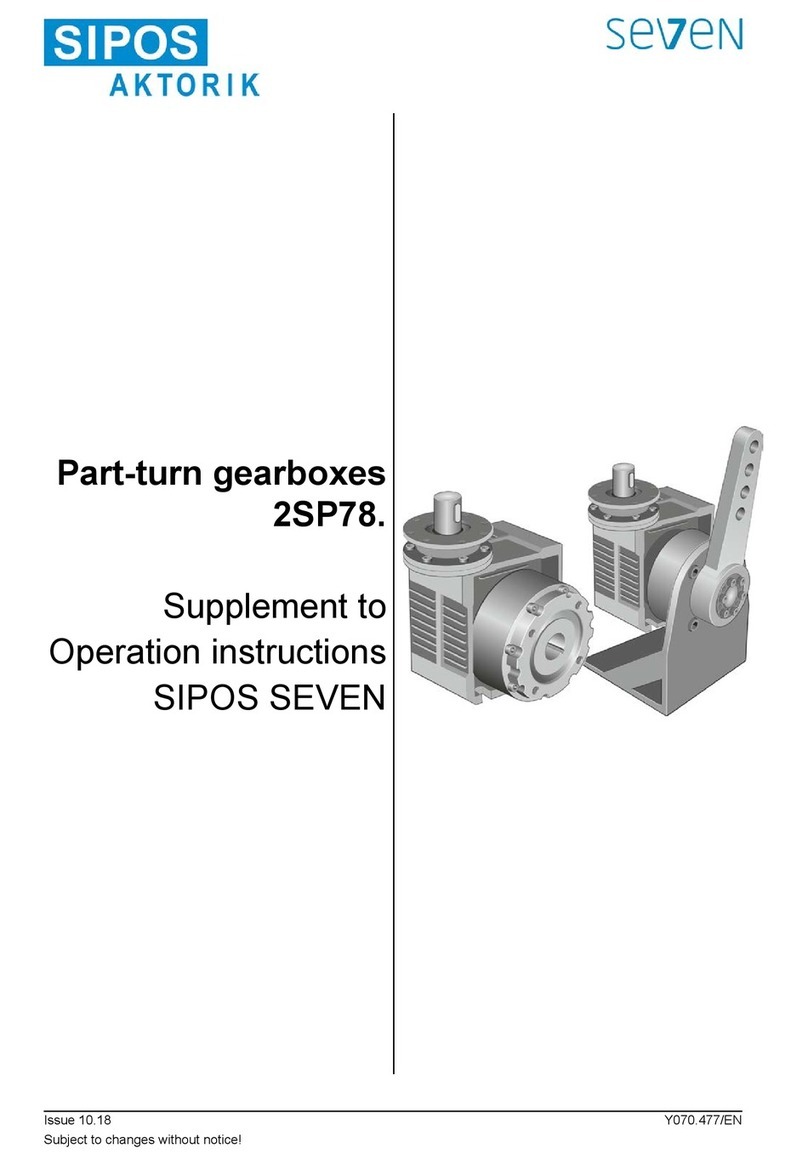
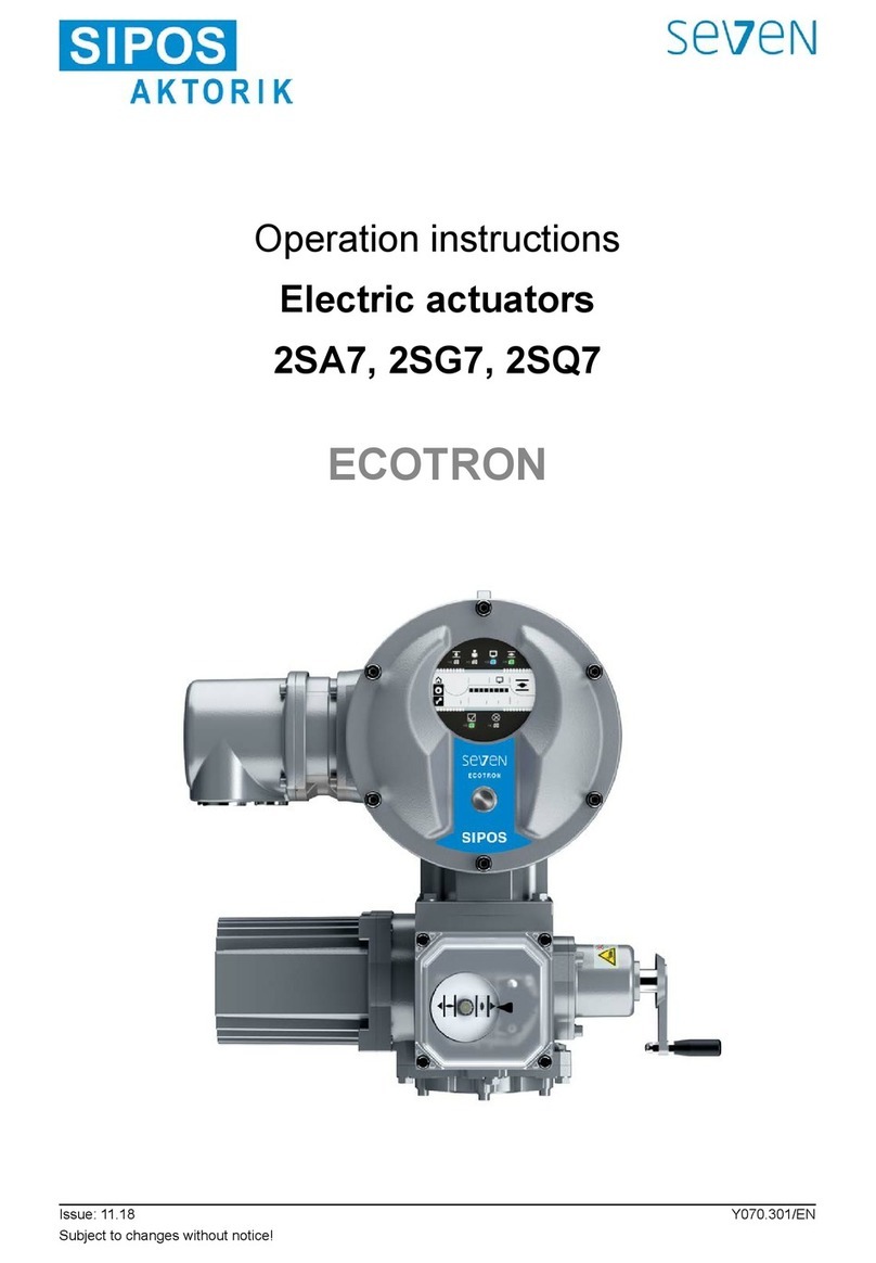
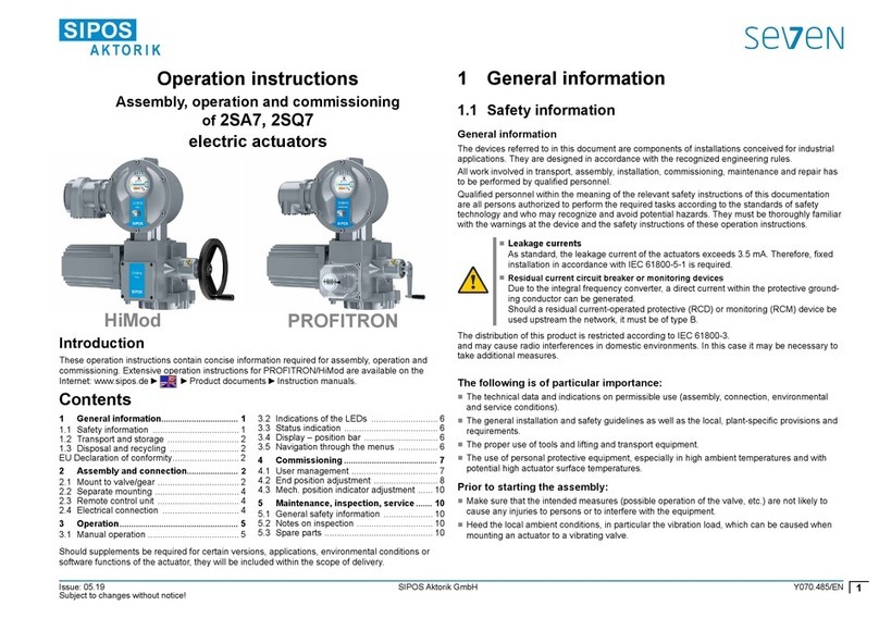
SIPOS Seven Aktorik Ecotron 2SA7 User manual

Operation instructions
Electric actuators
2SA7, 2SG7, 2SQ7
Issue: 05.18 Y070.302/EN
Subject to changes without notice!
PROFITRON HiMod

Operation instructions
SIPOS SEVEN: PROFITRON, HiMod
Page 2 Y070.302/EN
Contents
Contents
Contents
1 General information ������������������������ 4
1.1 Safety information ................................. 4
1.2 Transport and storage ........................... 5
1.3 Disposal and recycling .......................... 5
1.4 Notes to the operation instructions ........ 5
1.4.1 Warnings: Used symbols and
their meanings ....................................... 5
1.4.2 Scope .................................................... 6
1.5 Supplementary operation instructions ... 6
2 General information ������������������������ 7
2.1 Functional principle ............................... 7
2.2 Sub-assemblies ..................................... 8
2.3 Block diagram (electrical connections) .. 9
3 Assembly and connection����������� 10
3.1 Mount to valve/gear ............................. 10
3.1.1 General assembly instructions
for all output shaft types ...................... 10
3.1.2 Output shaft type A .............................. 10
3.1.3 Mount stem protection tube ................. 11
3.2 Electrical connection ........................... 12
3.2.1 Connection with round plug ................. 12
3.2.2 Fieldbus connection ............................ 13
3.2.3 External potential conductor
connection ........................................... 13
3.3 Separate mounting .............................. 14
4 Instructions on operator
control and operation ������������������� 15
4.1 Crank handle, hand wheel .................. 15
4.2 Light emitting diodes (LED)
and display .......................................... 16
4.2.1 Overview of light emitting diodes ........ 16
4.2.6 Overview of status indication .............. 16
4.3 Actuator status indication .................... 18
4.4 Navigation through the menus ............ 23
4.4.1 Operation of the Drive Controller ....... 23
4.4.2 Explanation of symbols,
texts within menu ................................ 24
5 Start menu ��������������������������������������� 26
5.1 Control ................................................. 26
5.1.1 "LOCAL“ control mode:
‘Local' actuator operation .................... 27
5.1.2 ”REMOTE“ control: ........ 28
5.1.3 “OFF“ control: ................ 28
5.2 Language selection ............................. 29
5.3 Main menu overview ........................... 30
6 User management�������������������������� 31
6.1 General information ............................. 31
6.2 General procedure .............................. 31
6.3 Assign password to user level/
change password of a user level ......... 32
6.4 Enable user level ................................. 33
7 Commissioning ������������������������������ 34
7.1 General information ............................. 34
7.2 Additional gear .................................... 36
7.2.1 Select additional gear and
change parameters ............................. 37
7.2.2 Parameters and their values
in the ‘Additional gear’ menu ............... 38
7.3 Program closing direction, speeds,
cut-off modes and tripping torques ...... 40
7.3.1 Select the closing direction ................. 40
7.3.2 Program speeds/positioning times ...... 41
7.3.3 Program cut-off modes
and tripping torques/forces ................. 42
7.4 Adjust end positions for version
with signaling gear .............................. 45
7.4.1 General information ............................. 45
7.4.2 Signaling gear ratio ............................. 47
7.4.3 Procedure for initial end position
adjustment ........................................... 48
7.4.4 Readjust end positions ........................ 53
7.4.5
Adjust mechanical position indicator ... 55
7.5 Adjust end positions for version with
"non-intrusive" position encoder .......... 56
7.5.1 New setting (initial setting) .................. 56
7.5.2 Readjust end positions ........................ 59
8 Parameters and possible
parameter values ��������������������������� 61
8.1 Parameter menu ................................. 61
8.2 Valve-specicparameters ................... 62
8.2.1 Change parameters in the
'Valve' menu ........................................ 62
8.2.2 Parameters and their values
in the ‘Valve’ menu .............................. 64
8.3 Control system parameters ................. 66
8.3.1 Overview of Control system menu ...... 66
8.3.2 Operation sequence: Changing
the parameters in the
'Control system' menu ......................... 67
8.3.3 Control system – Control mode ........... 67
8.3.4 Control system – Alternative
control mode ....................................... 69
8.3.5 Control system– Binary input .............. 70
8.3.6 MODE input ........................................ 70
8.3.7 Control system – Analog input AI1 ...... 71

Y070.302/EN Page 3
Operation instructions
SIPOS SEVEN: PROFITRON, HiMod
Contents
Contents
8.3.8 Control system – Analog input AI2 ...... 71
8.3.9 Control system – Binary outputs ......... 71
8.3.10 Control system – Analog output AO1 .. 73
8.3.11 Control system – Analog output AO2 .. 74
8.3.12 Control system – Fieldbus ................... 74
8.4 Safety related parameters ................... 77
8.4.1 EMERGENCY input ............................ 77
8.4.2 EMERGENCY speed .......................... 77
8.4.3 EMERGENCY position ........................ 78
8.4.4 Fault control source ............................ 78
8.5 Software functions ............................... 78
8.5.1 Enabling software functions
and customer variants ......................... 79
8.5.2 Positioner ............................................ 80
8.5.3 Proportional move ............................... 81
8.5.4 Optional software functions ................. 82
8.6 Special parameters ............................. 83
8.6.1 Tag number ......................................... 84
8.6.2 Separate mounting .............................. 84
8.6.3 Intermediate contacts .......................... 84
8.6.4 Motor ................................................... 85
8.6.5 Maintenance intervals of valve ............ 86
8.6.6 Check maintenance ............................ 86
8.6.7 Close tightly ......................................... 87
8.6.8 Rise time ............................................. 87
8.6.9 DC brake ............................................. 87
8.6.10 Delay of Power Failure Message ........ 88
8.6.11 Torquemeasurementange ............... 88
8.6.12 Thresholds for detection
of wire break at analog outputs .......... 88
8.6.13 Test operation ...................................... 89
8.6.14 DC link voltage limitation ..................... 89
8.6.15 Runtime monitoring ............................. 90
8.6.16 End position speed .............................. 90
8.6.17 Autom. TL adapt. end position ............ 91
8.6.18 DCS acceptance time ......................... 92
9 System settings������������������������������ 93
9.1 Display ................................................ 93
9.1.1 Display orientation ............................... 93
9.1.2 Standby screen ................................... 94
9.1.3 Fast to local ......................................... 95
9.1.4 Set standby time ................................. 95
9.1.5 Activate Standby ................................. 95
9.2 Adjust real time clock .......................... 95
9.3 Activate, deactivate Bluetooth ............. 96
9.4 Remote control unit ............................. 96
10 Torque curve ����������������������������������� 98
10.1 General information ............................. 98
10.2 Record torque curve ............................ 99
10.3 Save torque curve on
USBashdrive ................................. 100
11 Observe ������������������������������������������ 101
11.1 Electronic name plate ........................ 101
11.1.1 Tag number ....................................... 101
11.1.2 Order number and equipment .......... 101
11.1.3 Serial number .................................... 101
11.1.4 Original serial number ....................... 101
11.1.5 Firmware version ............................... 102
11.2 Inputs and outputs (observe) ............ 102
11.2.1 Binary inputs ..................................... 102
11.2.2 Analog input and outputs .................. 102
11.2.3 Torque switch (2SQ7 only) ................ 102
11.2.4 Fieldbus communication ................... 102
11.3 Actuator status .................................. 103
11.4 Torque zero adjustment ..................... 104
12 Diagnosis (operating data
and maintenance limits)������������� 105
12.1 Operation data actuator .................... 105
12.2 Valve maintenance limits ................... 106
12.3 Maintenance valve ............................ 106
13 Communication and
data exchange ������������������������������ 107
13.1 Remote control .................................. 107
13.2 COM-SIPOS PC parameterization
software ............................................. 107
13.3 USB port ............................................ 108
13.4 DataexchangeviaUSBashdrive... 108
13.4.1Updatermware................................ 109
13.4.2 Save parameters on
USBashdrive ................................. 109
13.4.3 Load parameters from
USBashdrive ................................. 109
13.4.4 Save torque curve ............................. 109
13.4.5 Clone actuator ................................... 110
14 Maintenance, inspection,
service ��������������������������������������������� 111
14.1 General information ............................111
14.2 Lubrication intervals and lubricants ... 112
14.3 Lubricant assignment and quantity ... 112
15 Spare parts ������������������������������������ 113
15.1 General information ........................... 113
15.2 Spare parts list .................................. 113
15.3 Exploded views ................................. 114
15.3.1 Gear unit 2SA7...- ............................. 114
15.3.2 Small part-turn gear unit 2SG7...- ..... 115
15.3.4 Small part-turn gear unit 2SQ7...- ..... 116
15.3.5 Electronics unit .................................. 117
Index �����������������������������������������������������118
EU Declaration of conformity/
Declaration of incorporation
in accordance with Machinery
Directive ������������������������������������ 123

Operation instructions
SIPOS SEVEN: PROFITRON, HiMod
Page 4 Y070.302/EN
1 General information
1
General information
1 General information
1�1 Safety information
General information
The devices referred to in this document are components of installations conceived for industrial
applications. They are designed in accordance with the recognized engineering rules.
All work involved in transport, assembly, installation, commissioning, maintenance and repair has to
beperformedbyqualiedpersonnel.
Qualiedpersonnelwithinthemeaningoftherelevantsafetyinstructionsofthisdocumentationare
all persons authorized to perform the required tasks according to the standards of safety technol-
ogy and who may recognize and avoid potential hazards. They must be thoroughly familiar with the
warnings at the device and the safety instructions of these operation instructions.
Forworkonpowerinstallations,theprohibitionoftheuseofnon-qualiedpersonsorsimilaris
stipulated in EN 50110-1 (formerly DIN VDE 0105) or IEC 60364-4-47 (VDE 0100 part 470).
■Leakage currents
Asstandard,theleakagecurrentoftheactuatorsexceeds3.5mA.Therefore,xedinstallation
in accordance with IEC 61800-5-1 is required.
■Residual current circuit breaker or monitoring devices
The integral frequency converter can be used to generate a direct current within the protective
grounding conductor.
Should a residual current-operated protective (RCD) or monitoring (RCM) device be used up-
stream the network, it must be of type B.
Correct transport, proper storage, mounting and installation, as well as careful commissioning are
essential to ensure trouble-free and safe operation.
The distribution of this product is restricted according to IEC 61800-3
and may cause radio interferences in domestic environments. In this case it may be necessary to
take additional measures.
The following is of particular importance:
■The technical data and information concerning the permissible use (installation, connection, am-
bient and operating conditions) provided in the catalog, order documents, operation instructions,
name plate data and in the other product documentation;
■The general installation and safety guidelines;
■Thelocal,plant-specicregulationsandrequirements;
■The local ambient conditions, in particular the vibration load, which can be caused when mount-
ing an actuator to a vibrating valve
■The proper use of tools and lifting and transport equipment;
■The use of personal protective equipment, especially in high ambient temperatures and with
potential high actuator surface temperatures.
Warnings on the device
Danger of crushing. When pressing in the crank
handle or the hand wheel ensure that neither the hand
northengersarecrushed,refertogure.
Applicable for devices of the 2SA7.5/6/7/8 series:
Indicates the lubricant used.
Refer also to chapter „14.2 Lubrication intervals and
lubricants“ on page 112.
Hot surface. Risk of hot surface temperatures (caused
by high ambient temperatures and frequent operation
as well as long activation times).
Fig�: Danger of crushing

Y070.302/EN Page 5
Operation instructions
SIPOS SEVEN: PROFITRON, HiMod
1
General information
1 General information
1�3 Disposal and recycling
Packaging
The packaging of our products consists of environmentally friendly materials which can easily be
separated and recycled. We use the following packaging materials: Wood-based panels (MSB/
OSB), cardboard, paper, PE foil. For the disposal of the packaging material, we recommend recy-
cling and collection centers.
Actuator
Our actuators have a modular design and may therefore be easily disassembled, separated and
sorted according to materials, i.e.: electronic parts, different metals, plastics, greases and oils.
The following generally applies:
■Collect greases and oils during disassembly. As a rule, these are substances hazardous to water
and must not be released into the environment.
■Arrange for controlled waste disposal of the disassembled material or for separate recycling
according to materials.
■Observe the national/local regulations for waste disposal.
1�4 Notes to the operation instructions
1�4�1 Warnings: Used symbols and their meanings
The following symbols, which have different meanings, are used in the operation instructions.
Non-observance of safety instructions may lead to serious injuries or damage.
Warning marks activities which, if not carried out correctly, can affect the safety of persons or
property.
Noticemarksactivitieswhichhavemajorinuenceonthecorrectoperation.Non-observanceof
these notes may lead to consequential damage.
Electrostatically endangered parts are located on circuit boards which may be damaged or de-
stroyed by electrostatic discharges. If the boards need to be touched during setting, measurement
or for exchange, it must be assured that immediately before touching an electrostatic discharge
through contact with an earthed metallic surface (e.g. the housing) has taken place.
Procedure may have been performed by valve manufacturer:
If actuators are delivered mounted to a valve, this step has been done in the valve manufacturer’s
factory. The setting has to be checked during commissioning.
1�2 Transport and storage
■The device must be supplied in sturdy packaging.
■For transport, loop the rope around the hand wheel housing,
refer to illustration. Only use the eyes (1) on the electronics
unit to lift the actuator's own weight.
■Do not attach the ropes and hooks at the crank handle or
hand wheel for the purpose of lifting.
■Store in well-ventilated, dry room.
at –30 °C – +80 °C.
■Protectagainstdampoorsbystoringonashelforpallet.
■Keep connection hood/cover and cable glands as well as the
cover of the electronics unit closed.
Fig�: Transport

Operation instructions
SIPOS SEVEN: PROFITRON, HiMod
Page 6 Y070.302/EN
1 General information
1
General information
1�4�2 Scope
For the sake of clarity, not all details of all versions of the product are described in these operation
instructions, nor can they cover all conceivable cases regarding installation, operation and mainte-
nance.Forthisreason,theoperationinstructionsonlycontaininstructionsforqualiedpersonnel
(refer to section 1.1) that are necessary when the equipment is used for the purpose for which it is
intended or in industrial applications.
If the devices are used in non-industrial applications with increased safety requirements, they have
to be ensured by additional safety measures during assembly.
In case of any questions, and especially where detailed product information is not available, contact
the sales representative in charge. Always state the type designation and the serial number of the
respective actuator (see name plate).
It is recommended that the services and support of the responsible SIPOS Aktorik service centers
are utilized for all planning, installation, commissioning and service tasks.
The contents of these operation instructions and product documentation shall not become part of or
modify any prior or existing agreement, commitment or legal relationship. The Purchase Agreement
contains the complete and exclusive regulation on material defect liability of SIPOS Aktorik. These
contractual regulations are neither amended nor limited by the descriptions contained in these
operation instructions and documentation.
1�5 Supplementary operation instructions
2SG7 small electric part-turn actuators
2SQ7 small electric part-turn actuator
COM-SIPOS PC parameterization software
PROFIBUS operation instructions
MODBUS operation instructions
HART operation instructions
Enclosure protection IP68-8 m "K51“
Increased vibration resistance "K57“, "K58“
Increased vibration resistance according to seismic class S2A "K59“
Very high corrosion protection
corrosivity category C5 with long protection duration "L38"
SIPOS SEVEN with USP
Binary and analog inputs freely available via bus
and other
Any special installation and operation instructions furnished by the suppliers of subcontracted com-
ponents,attachmentsorxturesareattachedtothesetofinstructionsandhavetobeobserved.

Y070.302/EN Page 7
Operation instructions
SIPOS SEVEN: PROFITRON, HiMod
2
General information
2 General information
2 General information
2�1 Functional principle
Description
The electronics with integral frequency converter (1) controls the motor (2). The motor turns the
output drive shaft (4) via the worm shaft (3). The output drive shaft (4) drives a gear or a valve stem
(5) via a stem nut.
The motion of the worm shaft (3) is transferred via the signaling shaft (6) to
■the signaling gear (7a). The signaling gear reduces the movement and turns the potentio-
meter (8)�
or:
■the non-intrusive position encoder (niP) (7b) for "non intrusive“ version. The non-intrusive position
encoder counts the number of rotations and records the position within one rotation. The position
recording is also performed without external power supply.
From the position of the potentiometer or the non-intrusive position encoder, the electronics recog-
nizes the position of the output shaft (9) and therefore the position of the operated valve. The motor
is controlled according to the process requirements.
The torque detection (TD) is performed electronically.
Fig�: Functional principle
TD

Operation instructions
SIPOS SEVEN: PROFITRON, HiMod
Page 8 Y070.302/EN
2 General information
2
General information
2�2 Sub-assemblies
The actuators of the SIPOS SEVEN series
comprise two main assemblies: gear unit and
electronics unit.
For details, refer to chapter „15.3 Exploded
views“.
The main sub-assembly gear consists of
the sub-assemblies:
1 Plug element electronic connection,
2 Motor,
3 Gear unit,
4 Signaling gear or non-intrusive position en-
coder (not for 2SG7) with cover,
5 Manual drive (with crank or hand wheel),
6 Possible mechanical extensions, depending
on the version.
For the 2SG7 and 2SQ7 small part-turn actua-
tors, the signaling gear is omitted and the gear
unit has a different shape. For 2SG7, the manual
drive has a different design.
The main sub-assembly electronics unit
consists of the sub-assemblies:
1 Electrical connection (two versions available),
2 Plug element gear connection,
3 Electronic housing with cover,
4 Power control PCB, including power module,
Fig�: Gear unit sub-assemblies
Fig�: Electronics unit sub-assemblies
5 Relay board (option),
6 Control PCB with display
7 Additional analog module for additional input
and output (option) or HART control input
(option).

Y070.302/EN Page 9
Operation instructions
SIPOS SEVEN: PROFITRON, HiMod
2
General information
2 General information
2�3 Block diagram (electrical connections)
The block diagram shows the electronic sub-assemblies and the inputs and outputs for possible
customer-specicconnections.
Fig�: Block diagram

Operation instructions
SIPOS SEVEN: PROFITRON, HiMod
Page 10 Y070.302/EN
3 Assembly and connection
3
Assembly and connection
3 Assembly and connection
3�1 Mount to valve/gear
If actuators are delivered mounted to a valve, this step has been done in the valve manufacturer’s
factory. However, the setting has to be checked during commissioning.
■Heed safety information (refer to chapter 1.1)!
■Prior to starting the assembly
– Make sure that the intended measures (possible operation of the valve, etc.) are not likely to
cause any injuries to persons or to interfere with the equipment.
– Heed the local ambient conditions, in particular the vibration load, which can be caused
when mounting an actuator to a vibrating valve
■During assembly, the output shaft insert may fall out of the output drive shaft.
■When disassembling the electronics cover, make sure the insert does not fall down.
It is recommended that the services and support of the responsible SIPOS Aktorik service centers
are utilized for all planning, installation, commissioning and service tasks.
3�1�1 General assembly instructions for all output shaft types
■Mounting and operation is possible in any position. Heed the local ambient conditions, in particu-
lar the vibration load, which can be caused when mounting an actuator to a vibrating valve.
■Do not apply force and avoid shocks!
■Thoroughlycleanmountingfacesofoutputmountingangesatactuatorandvalve/gear.
■Slightly grease the connection points.
■Place the actuator on the valve/gear, making sure it is properly centered.
■The bolts used upon delivery are not greased. Use bolts with at least 8.8 quality. If similar stain-
less steel bolts are used, they should be greased slightly using petroleum jelly.
The depth of engagement should be at least 1.25 x the thread diameter.
■Position the actuator on the valve/gear and tighten the bolts evenly in diagonally opposite se-
quence.
■The housing of the SIPOS SEVEN actuator consists of an aluminum alloy which is corrosion re-
sistant under normal environmental conditions. If the paint was damaged during assembly, it can
be touched up with original paint supplied in small quantity units by SIPOS Aktorik.
3�1�2 Output shaft type A
Assembly instruction
The stem nut is screwed onto the valve stem by turning the crank handle or the hand wheel.
Spring-loaded A end shafts are subject to high pre-tension. Fitting and removal of the stem nut for
thread cutting must be performed in accordance with assembly instructions!
Fitting and removing the stem nut
Ifthestemnutwasnotorderedwithatrapezoidalthread(sufx"Y18"toordernumber),orifthe
stem nut is worn and has to be replaced, proceed as follows:
Output ange (g., item 1) does not have to be removed from the rotary actuator!

Y070.302/EN Page 11
Operation instructions
SIPOS SEVEN: PROFITRON, HiMod
3
Assembly and connection
3 Assembly and connection
1.Unscrewcenteringring(g.,item5)from
outputange.
2. Take off stem nut (4) together with axial
needle-roller assembly and axial bearing
washers (3).
3. Remove the axial needle-roller assembly and
the axial bearing washers (3) from the stem
nut.
4. Only if the stem nut was delivered without
thread: Cut a thread in the stem nut (4)
(check the concentricity and the axial run-out
when clamping the stem nut) and clean it.
5. Lubricate axial needle-roller assembly and
axial bearing washers (3) with ball bearing
greaseandtthemonthenewormachined
stem nut (4).
6. Insert stem nut (4) with axial needle-roller
assemblyintooutputange(clawshaveto
engage properly into the groove of the output
shaft of the actuator).
7. Screw in the centering ring (5) and tighten it
to the stop. Make sure that the radial shaft
seal (6) is inserted correctly.
8. Using a grease gun, press ball bearing
grease into the nipple until lubricant is dis-
charged between the centering ring (5) and
the stem nut (4).
For output shaft form A, ensure that the valve stem is greased separately!
3�1�3 Mount stem protection tube
1.Removefastener(g.,item1).
2. Check that the extended stem does not ex-
ceed the length of the protection tube.
3. Apply sealing compound to the thread and
the sealing faces (e.g. 732 RTV from Dow
Corning, Munich, Germany).
4. Screw in the stem protection tube (2).
Fig�: Output shaft type A installed
Fig�: Mount stem protection tube
Fig�: Output shaft type A
assembly

Operation instructions
SIPOS SEVEN: PROFITRON, HiMod
Page 12 Y070.302/EN
3 Assembly and connection
3
Assembly and connection
3�2�1 Connection with round plug
1. Unscrewconnectionhood(g.,item2)with
plug element (1).
2. Unscrew screw plugs from the required cable
entries in the connection hood.
3. Unscrew plug element (1) from connection
hood (2).
4. Screw in the cable gland (3) only slightly and
insert the connecting cables (4).
5. Connect the connecting cables in accordance
with the circuit diagram enclosed in the con-
nection housing, connecting the earth lead to
the provided terminal in the connection box.
6. Screw plug element (1) into the connection
hood(2)andthenxconnectionhood.
7. Tighten cable glands (3).
Fig�: Connection with round plug
3�2 Electrical connection
The components are designed as to ensure that once connected correctly, uninsulated, live parts
cannot be touched directly; i.e. protection against electric shock is provided in accordance with
IP2X or IPXXB.
Dangerous voltages are also applied when the motor is at standstill. Before opening the terminal
cover or the connection hood, disconnect the supply voltage from the actuator. Allow at least 1
minute for the capacitors to discharge and do not touch any contacts.
■Thesupplyvoltagemustalwaysliewithinthevoltagerangespeciedonthenameplate.
■For short-circuit protection and for disconnecting the actuator from the mains, fuses and discon-
nect switches have to be provided by the customer. For the current values for sizing refer to the
technical data.
■Mains cable: Use metal cable glands for mains connection.
■Signal cable: Use metal cable glands with cable shielding for the connection of the signal cable
to avoid the occurrence of electronic faults. The signal cable must be shielded and the shield
mustbexedorgroundedonbothsides.Ensurecarefulconnectionofthescreenwithinthe
cable gland!
■It must be ensured that the cable glands and seals(O-rings)arettedcarefullyandcorrectly
in order to guarantee the enclosure protection. For details of the permissible conductor cross-
sections, see wiring diagram.
■Cable glands and cables are not included in the scope of delivery.

Y070.302/EN Page 13
Operation instructions
SIPOS SEVEN: PROFITRON, HiMod
3
Assembly and connection
3 Assembly and connection
3�2�2 Fieldbus connection
1. Dismantleeldbusconnectionhousing(g.,
item 2) and connection cover (4).
2.Unscrewplugelement(1)fromeldbuscon-
nection housing (2).
3. Unscrew screw plugs from the required cable
glands in the connection hood.
4. Screw in the cable glands (5) only slightly and
insert the connecting cables (6).
Foreldbuscables,cableglandswithout
shieldaresufcient,refertopoint7below.
5. Connect the mains cables and, if required,
signal cables in accordance with the circuit
diagram enclosed in the connection housing,
connecting the earth lead conductor to the
provided terminal in the connection box.
6.Fitplugelement(1)intoeldbusconnection
housing (2) again.
7.Connecteldbusconnecting cables to the
bus termination PCB (3). Lead shielding (7)
under metal clamp (8).
8.Fitconnectioncover(4)andeldbusconnec-
tion housing (2) again.
9. Tighten cable glands (5).
a= If the actuator is the last device of the bus
segment, the termination resistor must be
set to ON or a termination must be done
externally.
b= Connection for external 24 V power supply.
Enables communication even if the mains
are disconnected.
c = Connection for PROFIBUS DP bus monitor
(Protocol Analyzer).
Fig�: Fieldbus connection
3�2�3 External potential conductor connection
The external potential conductor connection
can be used for functional grounding and not for
protective grounding.
1. Remove plastic fastener (1) from the elec-
tronics housing.
2. Fit potential conductor (4) and gripping disc
(5) (shims point in direction of the housing!)
with M5 screw (2) and washer (3). Fig�: Fit potential conductor

Operation instructions
SIPOS SEVEN: PROFITRON, HiMod
Page 14 Y070.302/EN
3 Assembly and connection
3
Assembly and connection
3�3 Separate mounting
If the ambient conditions such as extreme
vibration, high temperature and/or if access is
difcult,theelectronicsunitistobemounted
separately from the gear unit.
The assembly kit for mounting the gear unit
and electronics unit separately can be ordered
directly with the actuator or separately as an ac-
cessory (2SX7300-...). The assembly kit is pre-
assembled. If the assembly kit is ordered directly
with the actuator, it is included separately with
the actuator.
Before starting the work, disconnect actuator
from the mains!
Procedure
1.Installmountingbracket(g.,item3)atthe
mounting location of the electronics unit.
2. Remove electronics housing (1) from the gear
unit (6) and mount it on the mounting bracket
(3) with the O-ring (2).
3. Standard assembly, refer to A
Fit "Separate mounting“ assembly kit: Plug
cover with contact pins (4) on lower side of
wall bracket (3) and plug cover with contact
sockets (5) on the gear unit (6).
4. Assembly with stem protection tube, refer
to B
Turn connection hood by 90° or 180° to en-
sure that cables are not impaired by the stem
protection tube:
Remove screws (7) from round plug, turn
roundplugby90°to180°andxscrews
again. Continue as described in section 3.
Fig�: Separate mounting
A = Standard,
B = with stem protection tube
■Duringinstallation,itisimportanttoensurethattheO-ringsarettedcorrectlyinordertoguar-
antee the degree of protection.
■Generally, it has to be ensured that movable parts, e.g those of the swing lever, are not im-
paired by the cables.
■In exceptional cases, the motor might become very hot. Therefore the cables should not touch
the motor.
Specication of the connecting cable between the electronics unit and the gear
unit
The connecting cables are available in different versions:
■Standard lengths: 3 m, 5 m, 10 m;
■withadditionalequipment(lter)upto150m.
Forseparatemountingexceeding10mincludinglter,thevalue">10mwithLClter“hastobe
set for the "Separate mounting" parameter. Refer to “Special parameters” section „8.6.2 Separate
mounting“ on page 84.
The actuator can also be equipped with a remote control unit that allows local operation in
distances up to 100 m. The remote control unit has the function of a second local control unit.
Refer to „9.4 Remote control unit“ on page 96.

Y070.302/EN Page 15
Operation instructions
SIPOS SEVEN: PROFITRON, HiMod
4
Instructions on operator control and operation
4 Instructions on operator control and operation
4 Instructions on operator control and operation
4�1 Crank handle, hand wheel
■Motor driven operation of the crank handle/hand wheel is not permitted.
■After commissioning, the actuator must not be operated beyond the parameterized end posi-
tions using the crank handle/hand wheel.
■When pressing in the crank handle/ the hand wheel, make sure that the hand is removed be-
tween the crank handle/the hand wheel and the housing: Danger of crushing! See the following
operation step 3.
The crank handle/handwheel does not rotate during motor operation.
Operation
Operation of all actuators except for 2SG7
and 2SQ7:
1. The actuator must be at standstill (1).
2. Remove the clamp (option) (2). The clamp is
used as protection against accidental engag-
ing of the crank handle/the hand wheel, if
the actuator is exposed to heavy vibration or
water pressure (enclosure protection IP68).
3. Press crank handle/hand wheel in direction
of the gear housing against the spring force
(3) and turn (4). (Caution: Danger of crushing
when engaging!)
Fig�: Operate crank handle
If crank handle/hand wheel is pressed in, the motor stops. The actuator can only be operated elec-
trically once the crank handle/hand wheel is released.
If the actuator is operated manually in "REMOTE“ state and an operation command is present,
the actuator is immediately operated after releasing the crank handle/hand wheel.
For 2SG7 only:
Turn hand wheel without pressing it in. Manual operation interferes with motor operation: If the hand
wheel is turned during motor operation, the positioning time is either extended or reduced, depend-
ing on the direction of rotation.
2SQ7 only:
Only engage manual drive while motor is at
standstill, refer to illustration.
Manual operation is automatically disengaged
when switching on the motor.
The handwheel does not rotate during motor
operation!
Direction of rotation
Clockwise turning of crank handle/hand wheel leads to
■2SA7 rotary actuator: Clockwise rotation of the output drive shaft (exception: 2SA7.7. and
2SA7.8.)
■2SG7, 2SQ7 part-turn actuator: With view on the mechanical position indicator: clockwise rotation
at the coupling or at the swing lever.
Depending on the gear unit installed, the direction of rotation may vary.
Fig�: Engage manual operation for 2SQ7

Operation instructions
SIPOS SEVEN: PROFITRON, HiMod
Page 16 Y070.302/EN
4 Instructions on operator control and operation
4
Instructions on operator control and operation
4�2 Light emitting diodes (LED) and display
The actuator informs the user via
■Light emitting diodes (LED).
The light emitting diodes indicate the current status of the actuator.
■Display.
The graphic color displays informs the user on the status of the actuator. Clearly arranged repre-
sentation and menu structure allow for comfortable operation and parameter setting. The Drive
Controller (rotary push button) enables operation directly at the actuator.
This chapter contains an overview of light emitting diodes and the information they provide for the
user.
An overview of the display status indication shows the multitude of information available for the
user.
4�2�1 Overview of light emitting diodes
1 Depending on the actuator ordered, the col-
ors of the light emitting diodes might vary:
a) Standard,
b) With add. version C73.
2 LED (CLOSE).
TheCLOSELEDisashingiftheactuator
moves in CLOSE direction and is continuous-
ly illuminated, if the actuator is in end position
CLOSED.
3 LED LOCAL
The LOCAL LED is illuminated if "local" con-
trol is selected.
Fig�: LEDs
4 LED REMOTE
The REMOTE LED is illuminated if "REMOTE" control is selected.
5 LED (CLOSE).
TheOPENLEDisashingiftheactuatormovesinOPENdirectionandiscontinuouslyillumi-
nated, if the actuator is in end position OPEN.
Further descriptions included in these operation instructions always refer to the standard version
of the LEDs.
4�2�6 Overview of status indication
Display areas
If the Drive Controller (rotary push button) is
operated in the standby status, the display will
be activated and show the status indication. The
status indication has two areas, refer to illustra-
tion:
■A = The upper section provides actuator sta-
tus information.
■B = The lower section shows the start menu
which allows access to the different operating
and parameterization menus.
If the Drive Controller is not operated, the display automatically changes from the active state to
the standby state after a preset duration (default value: 10 min.):
– Display illumination is reduced and
– The display changes to standby screen.
Turning or pressing the Drive Controller resets the display to the active state.
Refer also to „Standby screen“ on page 94.
Fig�: Display areas

Y070.302/EN Page 17
Operation instructions
SIPOS SEVEN: PROFITRON, HiMod
4
Instructions on operator control and operation
4 Instructions on operator control and operation
1 Indicates the state of the actuator.
Refer to chapter „4.3 Actuator status indica-
tion“ on page 18.
2 Position indication
Thegureandthepositionbarindicatehow
far the actuator has progressed in position
OPEN.
The decimal places are displayed in accor-
dance with the actuator variant:
– HiMod – two decimal places;
– PROFITRON with niP – one decimal
place;
– PROFITRON with signaling gear – no
decimal place;
If the actuator is in one of the end positions, an
end position symbol is indicated instead of the
number, refer also to g.2.
3 Symbol for end position OPEN , end posi-
tion CLOSED .
For a detailed description, refer to the fol-
lowing section "End position symbols and
position bars".
4 Symbols for control mode
They indicate the selected control mode:
"LOCAL“ , "REMOTE“ or "OFF“ ,
refer to chapter „5 Start menu“ on page 26.
5 Flag of the selected language.
6 Start menu
For a detailed description, refer to chapter „5
Start menu“ on page 26.
End position symbols and position bars
The top area of the status indication provides
information on the cut-off mode in the end posi-
tions and on the current status of the actuator.
1 Cut-off mode in end positions:
1a = Orange closed circle means 'torque-
dependent cut-off mode'.
1b = Green open circle means 'travel depen-
dent cut-off mode'.
2 End position range indication:
2a = End position range of end position
CLOSED.
2b = End position range of end position
OPEN.
The length of the indication bar represents the
scope of the end position range.
3 Indication during operation:
3a = The position bar indicates the progress
during operation (opening and closing
the valve). The value indicates in % how
far the actuator has been operated to
position OPEN.
3b = The symbol of the end position into
which the actuator is currently being
operatingisashing.
Fig� 1: Status indication
Fig� 2: Actuator in end position
a = End position OPEN; b = End posi-
tion CLOSED
Fig� 1: End position symbols and progress
bar
Texts/symbols in the status indication

Operation instructions
SIPOS SEVEN: PROFITRON, HiMod
Page 18 Y070.302/EN
4 Instructions on operator control and operation
4
Instructions on operator control and operation
The actuator state is indicated in the display,
refertog.,item1.
If a fault has occurred, the display shows a
warningsymbol(g.,item2)andahintwith
regard to potential causes. If the actuator is not
ready for operation, the display is framed in red
(item 4).
By selecting the fault signal, additional informa-
tion, e.g. possible remedies, are indicated.
Thegureinfrontofthemessage(g.,item3)
refers to the type of fault and allows unambigu-
ousidenticationbytheservicestaff.
Therstdigitoftheguresignies:
0 = operational state;
1, 8 = self-resetting fault;
2 = acknowledgeable fault;
3 = fault due to external causes;
4, 5, 6 = fault within the device.
For a detailed description of possible fault sig-
nals, refer to the table below.
Status messages in the display including explanation
Signal Explanation Possible remedy
01 Manual mode
■Hand wheel/crank handle is pressed.
■Cable to the hand wheel is defective
■Pull hand wheel/crank handle and/or
■Check feed cables and contact points of
electronics/gear!
Should this message occur sporadically, vibra-
tion could be the cause.
In this case, use brackets. Refer to „4.1 Crank
handle, hand wheel“ on page 15.
02 Emergency mode
An EMERGENCY signal is present.
The parameterized EMERGENCY position is approached.
03 Blocked in move
A block has been detected within actuator travel.
The actually required torque exceeds the set tripping torque
or
"Separatemounting"parameterissetto">10mwithlter",
althoughthereisnoLClteravailable.
Operate actuator into opposite direction. Should
the message occur rather frequently,
■Check valve and torque setting, increase trip-
ping torque if necessary or
use the ”Move again if blocked in move“ func-
tion!
■Check MOV for sluggishness.
■Check "Separate mounting“ parameter.
Fig�: Status indication
4 Should a block occur during operation, the
respective status message is indicated and
the remaining travel is represented as red
hatched area,refertog.2
5 If an EMERGENCY position or a setpoint
is being approached, the target position is
indicated by a symbol (vertical line on the
position bar).
6 If the actuator is in one of the end positions,
the respective symbol is shaded in blue.
= Block in OPEN direction
= Block in CLOSE direction
Fig� 2: Indication of operation direction dur-
ing block
Fig� 3: Indication Actuator in end position
OPEN
4�3 Actuator status indication

Y070.302/EN Page 19
Operation instructions
SIPOS SEVEN: PROFITRON, HiMod
4
Instructions on operator control and operation
4 Instructions on operator control and operation
Status messages in the display including explanation
Signal Explanation Possible remedy
04 Local blocked
Status signal only!
Localcontrolcanbedisabledviaeldbus.Incaseofa
eldbuscommunicationerror,localcontrolisautomatically
re-enabled.
05 REMOTE commissioning
Status signal only!
Actuator is commissioned in REMOTE mode.
Wait for termination of commissioning in RE-
MOTE mode.
11 Motor temp� too high
The motor has exceeded the maximum temperature of
155°C.
Possible reasons:
■Excessive ambient temperature,
■Excessive runtime,
■Too many switching cycles.
■Actually required torque too high or
■Short- circuited motor coil or connection to the motor tem-
perature sensor interrupted (2SG7 only).
■Parameterforseparatemounting">10mwithlter“not
set.
Note: The motor temperature monitoring can
be deactivated by programming at the actuator
(plant protection has priority over motor protec-
tion). However, the warranty for the actuator
immediately becomes void.
■Check operation conditions, valve as well as
motor;
■Check "Separate mounting“ parameter.
12 Overvoltage
Mains voltage too high (outside the tolerance +15 %). ■Check connection voltage,
■Check mains voltage for variations.
13 Undervoltage
Mains voltage too low (outside the tolerance –30 %). ■Check power supply!
■Check mains voltage for variations!
14 Power supply fault
Power supply failed or too low. ■Check power supply!
■Check connecting cable!
21 Run time error
After 3 % of the positioning time, the actuator has covered
less than 0.5 % travel. The positioning time is measured and
saved following the end position adjustment.
Possible reasons:
■Potentiometer contacts in the plug/socket connector were
ejected.
■Incorrect assembly and/ or setting of the potentiometer
after replacement.
■Motor cable interrupted (motor is not running).
■Error during position recording (the gear backlash between
potentiometer and central wheel is either too small or too
large: No change of position is detected although the motor
is running.)
■Signaling gear ratio was changed:
– Signaling gear turns in the opposite direction or
– Setting of the slide wheel (rev/stroke) in the signaling
gear is too high
■Actuator is blocked (actuator cannot be operated from
position/end position).
■Faultypotentiometer(lmisinterrupted).
■Parameterforseparatemounting">10mwithlter“not
set.
■Check valve, signaling gear, motor as well as
potentiometer!
■Check "Separate mounting“ parameter.
22 Process Interlock
STOP input is active. Only for binary control mode “Pulse
contact”.
Deactivate STOP input. Refer to chapter „8.3.3
Control system – Control mode“ on page 67.

Operation instructions
SIPOS SEVEN: PROFITRON, HiMod
Page 20 Y070.302/EN
4 Instructions on operator control and operation
4
Instructions on operator control and operation
Status messages in the display including explanation
Signal Explanation Possible remedy
23 Delay time
EMERGENCY input is active. Deactivate EMERGENCY input.
24 Motor lock
The “Enable motor operation” function is selected for the
mode input, however the signal for enabling motor operation
is missing.
Verify voltage level at mode input
or deselect function if activated by accident.
30 Execute last command
No signal from signal source (wire break).
The actuator continues to complete the last command in ac-
cordance with parameterization (OPEN, CLOSE, setpoint).
The actuator can be operated in "LOCAL“ control (e.g. hand
wheel, emergency operation, alternative control mode).
Check cables/contacts in the round plug.
31 Set end positions!
No valid end position adjustment available
The indication may have the following reasons:
■End position adjustment has not yet been performed,
■End position was passed due to hand wheel operation,
■Friction coupling of the signaling gear was twisted or the
signal gear reduction was changed or
■Cut-off type was changed (e.g. from torque-dependent to
travel-dependent)
Perform end position adjustment!
32 No AI 1 signal
This indication is only possible for live-zero setting
(4 – 20 mA).
ThresholdI:>21mAor<3.6mAexceededorfallenshortof.
Check input current!
33 Fault eldbus
Fieldbus communication interrupted (timeout). This error
status is only signaled as a fault if the REMOTE control is
performedviaeldbus.
Note: The bus address must deviate from the default setting
(126 for PROFIBUS and 247 for Modbus)!
Checkeldbuscommunicationandconnection!
34 No signal – Pos� held
No signal from signal source (wire break).
Actuator stops.
The actuator can be operated in "LOCAL“ control (e.g. hand
wheel, emergency operation, alternative control).
Check cables/contacts in the round plug.
35 No signal – EMERGENCY pos�
No signal from signal source (wire break).
Actuator performs an EMERGENCY operation.
The actuator can be operated in "LOCAL“ control (e.g. hand
wheel, emergency operation, alternative control).
Check cables/contacts in the round plug.
36 Keep actual process value
No signal (setpoint) from signal source (wire break).
When detecting a wire break, the last detected actual
process value will still be controlled. The actuator can be
operated in "LOCAL“ control (e.g. hand wheel, emergency
operation, alternative control mode). After change-over to
"REMOTE", the available actual process value will be con-
trolled.
Check cables/contacts in the round plug.
Other manuals for Seven Aktorik Ecotron 2SA7
1
This manual suits for next models
2
Table of contents
Other SIPOS Controllers manuals
