SIRCHIE ESP900 Manual

TI01-2ENG-REV13
100 HUNTER PLACE, YOUNGSVILLE, NC 27596 USA
Ph: (919) 554-2244, (800) 356-7311 • Fax: (919) 554-2266, (800) 899-8181 • Web: www.sirchie.com • Email: [email protected]
1 of 8
Copyright© 2013 by SIRCHIE
All Rights Reserved.
SIRCHIE®
Products • Vehicles • Training
TECHNICAL INFORMATION
Electrostatic Dust Print Lifter
Catalog No. ESP900
Information
One of the most overlooked forms of physical evidence at the crime scene is impression evidence. Locating
and recovering obvious kinds of impression evidence like tire tracks and
footprints is not the problem. It’s the not-so-obvious dust print impres-
sions that are difficult to locate, accidentally damaged or obliterated. The
Electrostatic Dust Print Lifter is designed specifically for lifting these
dust prints from almost any surface from the floor, door, wall or win-
dowsill to upholstered furniture using static electricity. High voltage is
applied to a metallized lifting mat creating a negative charge
and causing the ground plane to become positively charged.
Any dust present under the mat will take on a positive charge,
attracting it to the negatively charged mat.
The resulting dust print lifted will be a pre-
cise mirrored image of the original print.

TI01-2ENG-REV13
2 of 8
Application Lifting dust prints from a variety of porous and non-porous surfaces whether
horizontal, vertical, or curved.
Hazards/Safety Info Warning! Potential for electrical shock. Unit develops up to 10,000 volts of
static electricity even though it operates at a low current.
Caution! Arching may occur between the pickup mat and surface. If so,
reduce the charging voltage.
Caution! Do not touch charging mat or ground plane while voltage is being
applied.
Caution! Always reduce charging voltage to MIN before turning unit off and
discharge any residual voltage between the ground plane and pickup mat with
the static discharge cable provided.
ESP900
Contents
1- Electrostatic Voltage Control Unit
1- Ground Plane, nickel-plated steel, 4" x 6"
(10.2cm x 15.2cm)
1- Ground Plane Polycarbonate Insulating
Sheet, 5" x 7" (12.7cm x 17.8cm)
1- Insulated Roller
1- 9V Alkaline Battery
1- Static Discharge Cable
1- ESP901 Metallized Lifting Mats in protec-
tive tube, 5 ea.
1- Technical Information
1- Black Molded Copolymer Case; Dimen-
sions: 12.25" x 9" x 3.875"
(31.1cm x 22.9cm x 9.8cm); Weight: 3.1
lbs. (1.4kg)
Optional
Accessory
Items/
Reorder
Items
ESP901 ....2' x 3' Lifting Mats, 5 ea.
ESP902....2' x 3' Lifting Mats, 10 ea.
ESP903....2' x 3' Lifting Mats, 15 ea.
ESP904....1' x 2' Lifting Mats, 50 ea.
ESP905....25' roll Lifting Material
ESP906....50' roll Lifting Material
ESP908....Lifting Mat Evidence Box (39"
x 27" x 1") w/(1) evidence label
and (3) EIL02 evidence seals
ESP909.... (10) Lifting Mat Evidence Boxes
(39" x 27" x 1") w/(10) evidence
label and (30) EIL02 evidence
seals

TI01-2ENG-REV13
3 of 8
Control Panel
Indicator Lights
RED: High Voltage Ready
YELLOW: Low Battery
GREENs: Voltage LEDs
indicate the strength of the
voltage output
Voltage Control
Adjusts voltage level
Power Switch
Push-Button ON/OFF
Unit Base
Battery Access
Release Latch and instruc-
tion label for
operation of unit
Serial Number
For unit registration
Brass Electrodes
(1) Positively Charged
(2) Negatively Charged
Explanation
of LEDs
RED High Voltage Ready will light when an electrical path has been established
between the pickup mat and the ground plate.
GREEN Voltage LED’s indicate the strength of the voltage output. If no LEDs are lit
then no High Voltage is applied. One LED indicates approx. 4000 volts. Each ad-
ditional LED indicates an additional 1000 volts until the max. of 7 LEDs are lit repre-
senting 11,000 volts.
YELLOW Low Battery LED will illuminate shortly before battery life expires. Battery life
varies with use. A fresh 9V alkaline battery will provide about 150-200 lifts using a 15 sec-
ond charging cycle. (See Battery Installation.)

TI01-2ENG-REV13
4 of 8
Battery Installation
The Electrostatic Dust Print Lifter is powered by a single 9V
alkaline battery. The battery storage compartment is located on
the unit base. A single negatively charged brass electrode pro-
trudes through the battery compartment cover.
1. Just below the brass electrode on the bottom of the unit is
a release latch. Move the latch down and remove the cover.
The battery is installed in the bottom compartment.
2. Observe the polarity of the replacement battery. The “+” terminal is at the bottom
terminal in the compartment. Refer to label inside battery compartment.
3. Push the battery into place. A small plastic spacer tab is located at the left side of
the battery compartment. The battery should be installed just to the right of the
spacer tab with the terminals making contact.
4. With the battery in position, replace the compartment cover.
The unit is ready for use. Press the ON/OFF switch. The green button should illumi-
nate. NOTE: Energizing the unit will not produce an electrical charge (see OPERA-
TION).
Locating Dust Impressions
Locating dust impressions requires careful investigation techniques aided by employ-
ing special lighting. Whether prints are visible or not, the search for them should be
directed toward areas most likely traveled by the perpetrator. This would include hall-
ways, foyers, and the areas nearest to the point of entrance and exit. The texture of the
surface or strong design patterns may make this more difcult (pictured to the right.)
BATTERY ACCESS
The footprint in the
photo above is bare-
ly noticeable, but be-
comes easily visible
(as shown below) by
darkening the room
and using a white light
such as the one pro-
vided with the TMX100
Tactical MAX Forensic
Light Kit at an oblique
angle.

TI01-2ENG-REV13
5 of 8
Operation
1. Remove one of the pickup mats from its protec-
tive tube. Carefully place the mat, black side
down, over the area to be examined.
2. Position the Ground Plane 1-2 inches from one
edge of the pickup mat as shown (Fig. 1A).
NOTE: When working on vertical surfaces (Fig.
1B), secure the pickup mat and ground plate in
place with tape.
3. Place the electrostatic control unit on the ground
plane and the pickup mat. The single brass elec-
trode (uppermost—top) must make contact with the metallized surface of the pickup mat and the 2 brass
electrodes at the (lower) other end of the unit must contact the ground plane.
4. Press the ON/OFF button. The button should illuminate and the red LED below the voltage control knob
will illuminate if the unit is properly position over the pickup mat and ground plate. If the red LED does
not come on, make sure the brass electrodes are making good contact with the pickup mat and ground
plate.
5.
To apply voltage, turn the control knob one position clockwise. This will apply approximately 4000 volts.
On most surfaces, application of the electrical charge will cause the pickup mat to draw down to the
surface. If not, advance the voltage control to a higher value. Each click of the knob will apply approxi-
mately 1000 additional volts. Rotating the knob clockwise after all the LEDs are lit will have no effect.
If arching occurs between the pickup mat and the ground plate, lower the voltage by turning the control
knob counter clockwise.
FIGURE 1A FIGURE 1B

TI01-2ENG-REV13
6 of 8
NOTE: You will not receive an electrical shock by touching this knob,
provided that your other hand is not touching any other surface.
Touching the pickup mat or ground plane while the charge is being applied,
however, could result in electrical shock.
6. While the pickup mat is charging, use the insulated roller to atten out any
air bubbles between the mat and the surface being examined (Fig. 2).
7. Normal charging time is approximately 15-30 seconds. Longer charging
produces better results, but will shorten battery life. The pickup mat being at
against the surface is a good indication that further charging is not necessary.
8. Removing the unit from the surface will turn off the high voltage and auto-
matically reset the control knob to the High Voltage off position.
9. Lift the mat and examine the black surface for dust prints.
Lifting Dust Prints from Metal Surfaces
The ESP900 also lifts prints from metal surfaces such as desktops, vehicle
bodies, metal cabinets, and other metal surfaces. Place the ground plane insu-
lating sheet within an inch of the pickup mat (Fig. 3). Center the ground plane
on the insulating sheet leaving a 1/2" border around the ground plane.
Failure to use the Ground Plane Insulator may result in arcing between the pickup mat and the metal
surface of the pickup mat and may damage the surface being tested.
1. Switch the power ON and slowly increase voltage. On most metal surfaces, it will not be necessary to
go beyond the lowest voltage setting. Allow a charge for at least 15 seconds (30 seconds max).
2. After the charging cycle is complete, remove the unit.
FIGURE 3
FIGURE 2

TI01-2ENG-REV13
7 of 8
3. Using the Static Discharge Cable, press and hold the
plungers on both ends of the cable. This exposes a metal
contact at each end. Touch one contact to the ground
plane and the other to the metallized surface of the pick-
up mat simultaneously to discharge any residual charge
left in the mat (Fig. 4).
4. Carefully, lift and examine the pickup mat (Fig. 5). It
may not always be possible to see some of the lifted
prints due to low contrast of the dust with the black mat surface. Therefore, examine
the mat using oblique light.
Preserving Lifted Dust Prints
Photograph lifted dust prints and be certain to include a scale. The prints may be lifted
from the pickup mat using Rubber Footprint Lifter No. 647C100 or SIRCHIE’s GELifters™.
CAUTION! Attempts to add clear lacquer or similar materials to preserve the print on the lifting mat usually
results in the destruction of lifted prints.
CAUTION! Do not use lifting tape or residue lifters other than those recommended above—it is nearly im-
possible to separate the device from the mat. Static electricity may also cause the matt to be draw to the tape
prematurely, damaging the lift.
NOTE: Discard mats after the prints are recorded. While it may be possible to clean the mat, wrinkles and
scratches will develop across the surface and interfere with results from subsequent lifts.
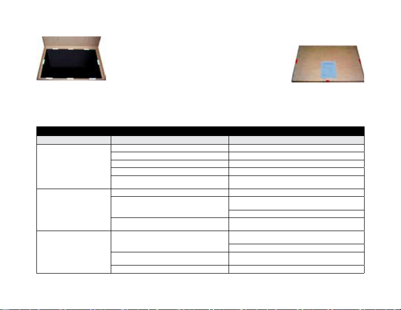
Transporting Lifting Mats
If the dust print lift must be transported to the lab for analysis, we recommend the use of ESP908 Dust Print
Evidence Box. Each evidence box is supplied with an evidence label for identication and chain of posses-
FIGURE 4
FIGURE 5
TI01-2ENG-REV13
8 of 8
Troubleshooting
Problem Possible Causes Solution
Unit does not turn on Battery not installed Install 9V alkaline battery
Battery installed incorrectly Check polarity
Battery dead Install new 9V alkaline battery
Power switch isn’t ON Push switch in to turn ON
Problem with internal circuitry Return to factory for repair. NOTE: Do not attempt repairs,
disassemble or alter unit as this will void your warranty.
No dust prints on pickup mat There were no dust prints present N/A
Lifting mat didn't draw down completely to
surface
Check positioning of brass contacts between the mat
and ground plane
Increase voltage setting
Brass contacts positioned incorrectly Check positioning of brass contacts between the mat
and ground plane
Lifted dust prints are very light Lifting mat didn't draw down completely to
surface
Check positioning of brass contacts between the mat
and ground plane
Increase voltage setting
Brass contacts positioned incorrectly Check positioning of brass contacts between the mat
and ground plane
Not all dust offers high contrast Darken room and use oblique lighting to examine
sion purposes. Secure the pickup mat (black side up) inside the transportation box
with tape as shown to the right (Fig. 6) and seal the
box with three evidence integrity seals. Afx the evi-
dence identication label to the outside (Fig. 7) and
complete the information for transportation to the lab.
References
Bodziac, William J., Footwear Impression Evidence, New York: Elsevier Science Publishing Co.: 1990, p103
Saferstein, Richard, Ph.D., Criminalistics, Sixth Edition, New Jersey: Prentis Hall: 1998, p324
Crime-Scene-Investigator, Dwayne S. Hilderbrand, CLPE: Footwear, The Missed Evidence, <http://www.crime-scene-investigator.net/footwear.
html> February 2009
FIGURE 7
FIGURE 6
Table of contents
Other SIRCHIE Camera Accessories manuals


