SIRCHIE FX10A Manual
TI03-328ENG-REV5
100 HUNTER PLACE, YOUNGSVILLE, NC 27596 USA
Ph: (919) 554-2244, (800) 356-7311 • Fax: (919) 554-2266, (800) 899-8181 • Web: www.sirchie.com • Email: [email protected]
1 of 12
Copyright© 2011 by SIRCHIE
All Rights Reserved.
SIRCHIE®
Products • Vehicles • Training
TECHNICAL INFORMATION
Forensic Video-Based Optical Comparators
Catalog Nos. FX10A, FX10AC
Upon initial receipt of the instrument, inspect for any visible damage. If the shipping carton(s) is damaged,
please point this out to the delivering carrier. If, after opening the carton(s), any damage is apparent, save
all packing material and contact Customer Service at 1-800-356-7311 immediately.
INTRODUCTION
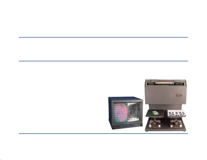
The new FX10 Series of Forensic Video-Based Optical Comparators have
been engineered to accommodate high-resolution video cameras matched to
superior optics and have newly developed internal
digital circuitry coupled to an eye-level control pan-
el. The FX10AC model features color video camera,
while the FX10A model has a black and white cam-
era and video monitor. These units will directly feed
video monitors, recorders or computers equipped
with video capture capability. Not just a ngerprint
projector, these instruments permit examination

TI03-328ENG-REV5
2 of 12
of a variety of items of forensic interest. The laboratory-grade focusing jacks permit viewing of both two-
dimensional and three-dimensional objects, and the optics offer exceptional depth of eld even when viewing
curved surfaces. Not only do you get both vertical and horizontal split screens for evidence comparison, you
also have the ability to overlay (superimpose) one image over another.
CAUTIONS
• HAZARDOUS VOLTAGES ARE PRESENT INSIDE THE UNIT. Should it become necessary to
remove the access panel, be certain that power has been disconnected.
• Prior to connecting power to the unit and/or use, please read through and follow the instructions.
• The unit and the monitor both accept a power source of 110-220V AC, 50/60 Hz and auto-sense the ap-
plied input voltage.
FX10A and FX10AC CONTROLS
1. ZOOM CONTROL: Controls Channel A magnication.
2. ZOOM CONTROL: Controls Channel B magnication.
LOWER/FRONT CONTROL PANEL:
3. POWER: Master Power ON/OFF control.
4. LIGHTS: Activates both uorescent lights.
UPPER CONTROL PANEL:
5. CAM A: Activation shows 100% of Camera A image in display. Red indicator will light to right of switch.
6. CAM B: Activation shows 100% of Camera B image in display. Red indicator will light to right of switch.
7. L/R: Activation splits screen vertically with CAM A image on the left and CAM B image on the right;
adjust amount of split with MIX control. Green indicator will light to right of switch.

TI03-328ENG-REV5
3 of 12
8. T/B: Activation splits screen horizontally with CAM A image on top and CAM B image on bottom;
adjust amount of split with MIX control. Green indicator will light to right of switch.
9. FADE: For overlay (latent to record print) capability. Activation superimposes CAM A on top of CAM B
with MIX control set to mid-range. Adjust amount of FADE: Clockwise enhances CAM A and eliminates
CAM B when turned full right; Counterclockwise enhances CAM B and eliminates CAM A when turned
full left. Yellow indicator lights to right of switch.
5 6 7 8 9 10 11 12 13 14
1 2
3
4
TI03-328ENG-REV5
4 of 12
10. DIFF: Activation superimposes CAM A on top of a reversed image of CAM B with MIX control set to
mid-range. Adjust amount of DIFF: Clockwise intensies CAM A and eliminates CAM B when turned
full right; Counterclockwise intensies CAM B and eliminates CAM A when turned full left. Red indica-
tor will light to right of switch.
11.FREEZE: Activation captures current position of CAM B image so you need only to reposition CAM A
image to align. This option can be activated when comparing in L/R, T/B, FADE, or DIFF modes. Blue
indicator will light to right of switch. NOTE: This only freezes CAM B, even if you’ve previously acti-
vated EXCH mode.
12. EXCH: Activation swaps CAM A and CAM B images. If in L/R mode, CAM B will now appear on the
left and CAM A on the right. If in T/B mode, CAM B appears on top and CAM A on bottom. Green in-
dicator will light to right of switch. NOTE: EXCH has no effect on images unless you are in split-screen
mode.
13. MIX: Rotary control knob
used to adjust position or
amount of split (L/R, T/B)
as well as the ratio of FADE.
NOTE: MIX has no effect
when CAM A or CAM B
switches are activated.
14. POWER: Activates splitter
power ON/OFF (upper con-
trol panel).
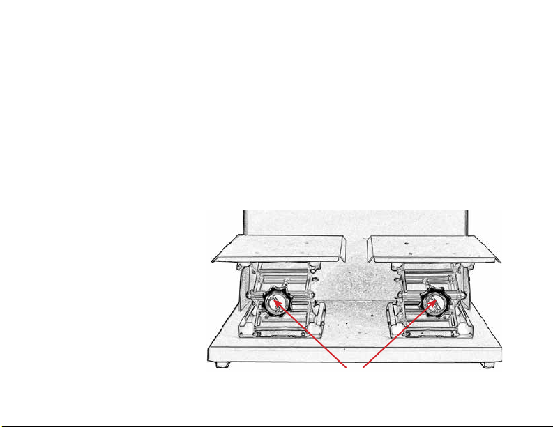
15. FOCUSING JACKS: Fo-
cuses Channel A and Channel
B respectively.
CHANNEL A CHANNEL B
15
TI03-328ENG-REV5
5 of 12
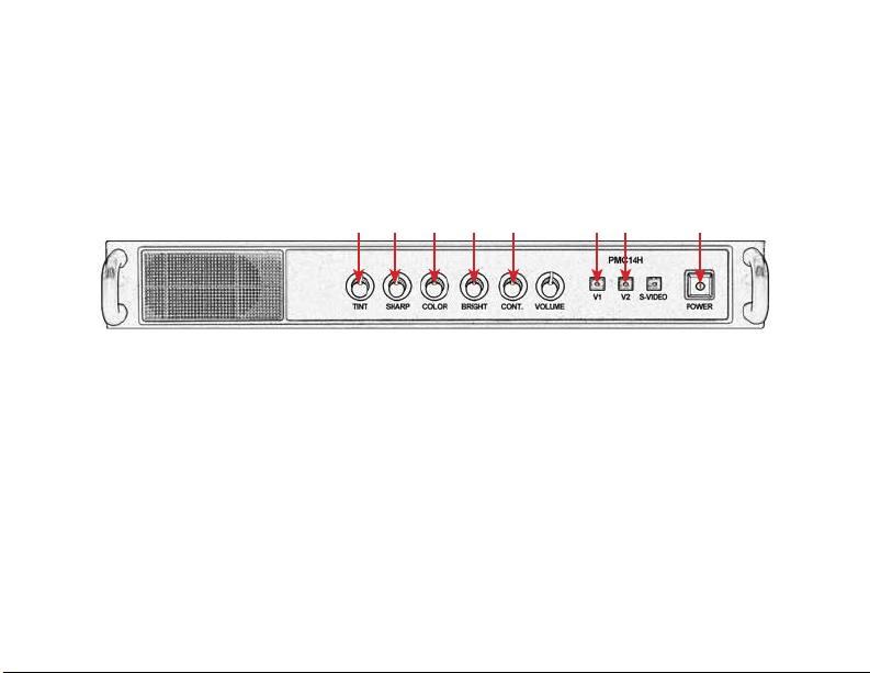
COLOR VIDEO MONITOR CONTROLS & HOOK-UPS
Included with your FX10 series units is a 14" diagonal video monitor. NOTE: The monitor for the FX10A
displays a black and white image; the monitor for the FX10AC is color. In order to visualize the evidence
you are comparing with the FX10A or FX10AC, the monitor must be connected. The monitor comes
equipped with hook-ups in the rear for connection to a computer, video recorder, and the like for download-
ing, recording, and storing the evidence you are comparing. NOTE: Only those controls applicable to the use
of the FX10 series units are covered.
1. TINT: Adjusts the tint of image on screen.
2. SHARP: Adjusts the sharpness of image on screen.
3. COLOR: Adjusts color saturation level of image.
4. BRIGHT: Adjusts the brightness of image.
5. CONT.: Adjusts the contrast of image.
6. V1: Activates Video 1 input option.
7. V2: Activates Video 2 input option.
8. POWER: Turns the color video monitor ON/OFF.
1 2 3 4 5 6 7 8
TI03-328ENG-REV5
6 of 12
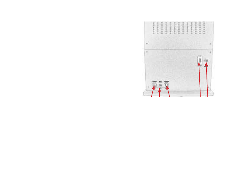
9. AC Input 110/220V
10. Fuse holder
11. AC Output
12. VGA OUT (15 pin)
13. NTSC Video Out
FEATURES
The FX10 Series Units include a wide range of features all
designed to minimize the workload of the evidence examiners.
These instruments permit examination of many different items
of forensic interest. While primarily designed for the examina-
tion and comparison of latent evidence, these instruments may
also be used for the examination of questioned documents, tool
marks, hair and ber evidence, and much more.
9 10 11 12 13
• Soft, indirect lighting with circular uorescent
tubes
• Laboratory-grade focusing jacks
• High resolution color video cameras (FX10AC)
• High resolution black and white video cameras
(FX10A)
• Vertical and horizontal, continuously variable
split-screen images
• Image overlay
• Image reversal (Channel B only)
• BNC-type video-out connector. *VGA output
(Resolution: NTSC 640 x 480)

TI03-328ENG-REV5
7 of 12
OPERATION
To better understand how the FX10 Series Units can be fully
utilized in the examination of forensic evidence, we suggest
you rst perform the following procedure of comparing a latent
print lift to a print on a 10-print ngerprint card (see Figure
1). These step-by-step instructions cover every aspect you may
encounter in the examination. For the purpose of this examina-
tion, set the Focusing Jacks midway between upper and lower
extremes—this is the focus point for two-dimensional objects
(latent lift, 10-print card, document, etc.) which allows the im-
age to remain in focus throughout the entire Zoom range. Note:
When examining three-dimensional objects, the jacks will need
to be lowered accordingly.
1. Plug the unit’s AC power cord into a convenient outlet and plug the TV
monitor into the back of the unit. Then, connect the Video Output from
the unit to the appropriate Video IN connector on back of monitor.
2. Place a latent print on the left Focusing Jack (Channel A). Place a 10-print
record card on the right Focusing Jack (Channel B). Adjust both jacks to
the mid-range height.
3. Switch all three switches on the Lower Front Control Panel to ON.
4. Switch the Upper Control Panel Power Switch to ON. Press the CAM A
switch and center the latent print under the lens (see Figure 2). Zoom to
full image size with the Channel A Zoom Control. Adjust Channel A Fo-
cusing Jack for sharpest focus.
FIGURE 1
FIGURE 2
FIGURE 3

TI03-328ENG-REV5
8 of 12
5. Press the CAM B switch and center the image under the lens (see Figure 3). Zoom to full image size
with the Channel B Zoom Control. Adjust Channel B Focusing Jack for sharpest focus.
6. Turn the MIX control knob to its mid-range setting.
7. Press the L/R Switch for vertical split-screen mode and adjust the MIX control knob to achieve the
desired split ratio. The previously centered
images will now be split in half with CAM A
image left and CAM B right (see Figure 4A).
This split would be ideal for comparing one
side of an image to the other. However, for
the purpose of comparison, re-center the prints
within the split frame and zoom as necessary
(see Figure 4B).
8. Press the T/B Switch for horizontal split-screen
mode and adjust the MIX control knob to
achieve the desired split ratio. The repositioned
images will now be split top-to-bottom with
CAM A image on top (appearing slightly to the
left), and CAM B on the bottom and slightly to
the right (see Figure 5A). However, for the purpose of comparison, re-
center the prints within the frame in CAM A and CAM B modes—zoom
as necessary (see Figure 5B).
9. Press the FADE Switch with the MIX control knob at its midpoint range.
CAM A image is now superimposed on top of CAM B (see Figure 6A).
Adjust the amount of FADE by turning the MIX control clockwise to
enhance CAM A image or counterclockwise to enhance CAM B. If the
FIGURE 4A FIGURE 4B
FIGURE 5A FIGURE 5B
FIGURE 6A

TI03-328ENG-REV5
9 of 12
MIX control is turned full right, CAM B is
eliminated (see Figure 6B); turned full left and
CAM A is eliminated (see Figure 6C).
10. Press the DIFF Switch with the MIX control
knob at its midpoint range. CAM A image is
now superimposed on top of a reversed image
of CAM B (see Figure 7A). NOTE: This mode
is particularly use-
ful when working
with prints devel-
oped with light-
colored powders.
Adjust the amount
of DIFF by turning
the MIX control clockwise to intensify CAM A image or counterclockwise to intensify CAM B. If
the MIX control is turned full right, CAM B is eliminated (see Figure 7B); turned full left and CAM
A is eliminated (see Figure 7C).
11. Press the FREEZE Switch to capture the current position of CAM B image. Now, you need only to
reposition CAM A image to align. This is especially useful when attempting to superimpose one print
over the other as in the FADE or DIFF modes. NOTE: The FREEZE mode actually captures the
image seen with CAM B. In other words, you can remove the ten-print card from the focusing jack
and not loose the previous image you’ve now captured—that is, until you deactivate FREEZE. The
FREEZE mode can be activated when comparing in L/R, T/B, FADE, or DIFF modes. Remember,
even if you had previously activated EXCH mode, only CAM B image will FREEZE.
12. Press the EXCH Switch to swap CAM A and CAM B images. If the unit is operating in L/R mode,
FIGURE 6B FIGURE 6C
FIGURE 7A FIGURE 7B FIGURE 7C

TI03-328ENG-REV5
10 of 12
CAM B will now appear on the left and CAM
A on the right (see Figure 8). If unit is in T/B
mode, CAM B appears on top and CAM A
on the bottom (see Figure 9). NOTE: EXCH
Switch has no effect on images unless you are
in a split-screen mode.
EXPLANATION AND COMPARISON OF OTHER TYPES OF EVIDENCE
FIGURE 7B FIGURE 7C
Threads of finely woven fabric. Match torn fabric easily. View fibers of torn paper in detail.
Discern prints from background. Latent prints viewed in L/R mode. Handwriting viewed in T/B mode.
TI03-328ENG-REV5
11 of 12
GENERAL MAINTENANCE
The only maintenance to be performed in the eld is cleaning and
lamp replacement. Lamp replacement is covered below. Clean the outer
surfaces with a mild soapy warm water solution and a soft cloth. DO
NOT use solvents as this may damage the nish.
Lamp Replacement
1. Disconnect the AC power cable and the video out cable from the
back of the unit.
2. Tip the unit onto its back. Lower the
stages fully to give comfortable access
to the lamps.
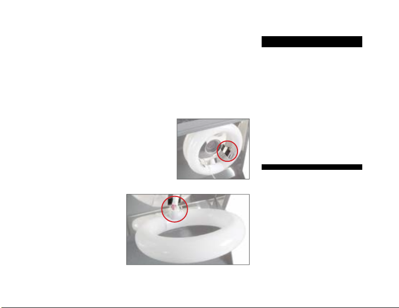
3. Three spring clips hold each lamp in
place (Figure 10). Gently pull the lamp
to be replaced toward you, away from
the retaining clips.
4. Unplug the lamp power connector
(Figure 11).
5. Plug the lamp power
connector into the new
lamp.
6. Place the new lamp
into the retaining clips.
FIG. 10—Lamp retaining ring.
FIGURE 11—Lamp connector.
FX10A SPECIFICATIONS
OPTICAL:
Zoom Ratio: ~8x
Aperture: f/7 (low mag.)-f/10 (high
mag.)
Magnification: ~5X - ~45X on 14"
diagonal monitor
Lens Construction: 10 elements/7
groups
Filter Size: M40.5 x P0.5
VIDEO SPLITTER:
Digital Memory: 512 x 512 w/256
Gray Levels
Video Signal: NTSC only

TI03-328ENG-REV5
12 of 12
COLOR VIDEO CAMERA x 2
TV System: NTSC Image
Sensor: 1/4" Interline Transfer CCD
Effective Picture Element: 768H x
492V pixels
Sync. Frequency:
• Horizontal: 15.734KHz
• Vertical: 59.94Hz
Resolution: 470 TV-lines
(horizontal)
S/N Ratio: More than 50Db
Minimum Illuminance: Less than
2.0 lx (f/1.2)
Gamma: 0.45
Video Output: 1.0Vp-p/75W
White Balance: Auto Tracking
White balance
OPTICAL x 2
Zoom Ratio: ~8x
Aperture: f/7 (low mag.)-f/10
(high mag.)
Magnification: ~5X - ~45X on 14"
diagonal color monitor
Lens Construction: 10 elements/7
groups
Filter Size: M40.5 x P0.5
VIDEO SPLITTER
Video Signal: NTSC only
Split Range:
• Horizontal: 0 to 53.3uS from
start of active video >98% of
screen width typical
• Vertical: 0 to 485 lines, fully
variable insteps of two, 100%
screen height typical
Fade Range: A:B ratio from
100%/0% to 0%/100%, 256 steps
Difference Range: A:B ratio from
100%/-0%to 0%/-100%, 256
steps
Memory: 10 megabits per
channel (full frame X1 each
input)
Decoding: 9 bit multi-standard
digital decoding
Processing: 8 bit, 4:2:2, ITU-R601
and ITU-R656 standards
Encoding: Full Digital Modulation
Oversampling: 4x (54MHz) output
oversampling
Output DACs: 10 bit Digital to
Analog converters
Output Filters: Digital, plus 4 stage
analog anti-aliasing filters
Horizontal Frequency: 15.734KHz
typical
Vertical Frequency: 59.94Hz
typical
Bandwidth: 6MHz typical
Crosstalk: Greater than 48dB
Gain Match A to B: Typ. within 1%
FX10AC SPECIFICATIONS
This manual suits for next models
1
Table of contents
Other SIRCHIE Camera Accessories manuals


