SIRI SIRIPRO 57 Operating instructions

1
since 1975
S.I.R.I s.r.l.
Via R.Dalla Costa, 44/46
41122 MODENA (ITALY)
T l. 059/313191 - Fax 059/311362
Email: [email protected] http//www.siri.mo.it
SIRIPRO
57 – 68 – 80 – 90
130 - 160
MANUALE D’USO E MANUTENZIONE
OPERATING AND MAINTENANCE MANUAL
MANUEL D’ EMPLOI ET ENTRETIEN
BEDIENUNGS UND WARTUNGSHANDBUCH

2
SIRI PRO 57-68-80-90-130-160
Fi .1
Fi .2
A
F

3
SIRI PRO 57-68-80-90-130-160 Manuale d’uso e manutenzione Ver 6.0
Fi .3
Fi . 4
Fi . 5
B

4
FIG.6 FIG 7
FIG 7.1 FIG 8
FIG.9 FIG 9.1
FIG 10 FIG 11
FIG 11.1 FIG 12
B
A
E
5
SIRI PRO 57-68-80-90-130-160 Manuale d’uso e manutenzione Ver 6.0
ART.
SIRI PRO 57
(art.
20057)
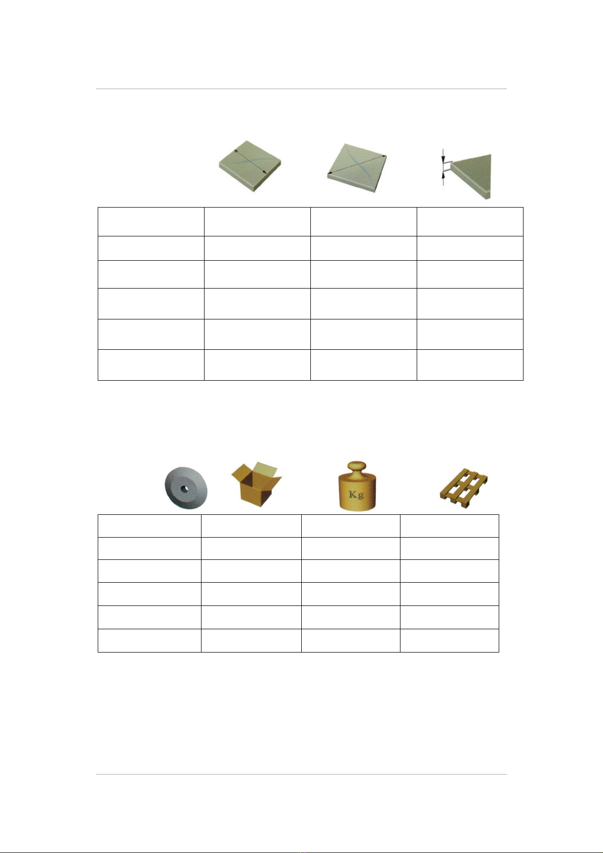
57 cm 40 x 40 cm 15 mm
SIRI PRO 68
(art. 20068)
68 cm
48 x 48 cm 15 mm
SIRI PRO 80
(art. 20080)
80 cm 57 x 57 cm 15 mm
SIRI PRO 90
(art. 20090)
90 cm 63 x 63 cm 15 mm
SIRI PRO 130
(art. 20130F)
130 cm 90 x 90 cm 15 mm
SIRI PRO 160
(art. 20160F)
160 cm 113 x 113 cm 15 mm
TAB. 1
TAB. 2
Ø 22 mm
80x34x26 mm 12 K 18 Pcs
Ø 22 mm
93x34x26 mm 13 K 14 Pcs
Ø 22 mm
104x34x26 mm 14 K 12 Pcs
Ø 22 mm
115x34x26 mm 17 K 8 Pcs
Ø 22 mm 150x45x30 mm 35 K 6 Pcs
Ø 22 mm 200x45x30 mm 45 K 4 Pcs

6
SIRI PRO 57-68-80-90-130-160 Manuale d’uso e manutenzione Ver 6.0
COMPONENTI DELLA TAGLIAPIASTRELLE (Fi .2)
La macchina è n i suoi l m nti principali così composta:
1) Bas
2) Asta di scorrim nto
3) Manico
4) Squadro
5) Prolunga
6) Squadr tto
MONTAGGIO TAGLIAPIASTRELLE
La taglia piastr ll vi n cons gnata al Cli nt all’int rno d ll’apposito carton o valig tta
(optional).
P r montar la tagliapiastr ll è quindi n c ssario:
1) Estrarr la macchina dal carton
2) All ntar il pom llo di blocco A d l carr llo di taglio Fi .3
3) Svitar il pom llo (A) ch f rma lo squadro n lla posizion di trasporto Fi .1.
Ins rir il fulcro d llo squadro n ll’apposito foro situato sulla bas sotto l’asta di
scorrim nto. Bloccar lo squadro n lla posizion d sid rata passando il pom llo
(A) n ll’asola d llo squadro avvitandolo n l foro pr disposto sulla bas Fi .2.
4) Svitar il pom llo (B), aprir la prolunga squadra (5) riavvitar il pom llo (B)
5) N l caso di incision di piastr ll di grandi dim nsioni strarr i supporti lat rali
(D) FIG. 2
INCISIONE A 90°
P r ff ttuar tal tipo di incision bloccar lo squadro contro l’apposito f rmo in modo
ch lo squadro st sso risulti p rp ndicolar all’asta di scorrim nto v di fig.6
Posizionar la piastr lla sulla bas , portandola a contatto con squadro squadr tto (avva-
l rsi d ll scal millim trich pr s nti su squadro squadr tto p r r golar l dim nsioni
d lla piastr lla da incid r ).
Incid r la piastr lla part ndo dalla part d ll’op rator . P r ff ttuar l’incision ,
impugnar il manico, alzarlo con il dito pollic o indic muov r il cursor in avanti
mant n rlo pr muto (fig.7) Abbassar il manico in modo ch la rot lla di taglio arrivi a
contatto con la piastr lla B Fi .4 e 7.1. T n ndo il manico abbassato sping r in
dir zion d llo squadro p r tutta la lungh zza d lla piastr lla fino ad ott n r un’incision
compl ta Fi 8.
S l’incision non avvi n in mani ra corr tta, tornar ad s guir l’op razion .
ROTTURA PIASTRELLA
Ad incision avv nuta p r romp r la piastr lla è n c ssario rilasciar il cursor , alzar il
manico in modo ch il cursor ritorni in posizion di riposo, così ch la rot lla di taglio
non sia più a contatto con la piastr lla. Poi abbassar di nuovo il manico ad una distanza
compr sa tra 1 2 cm dal bordo com indicato in fig.5 d s rcitar una pr ssion sulla
part t rminal d l manico com indicato in fi .9 9.1

7
SIRI PRO 57-68-80-90-130-160 Manuale d’uso e manutenzione Ver 6.0
INCISIONE E ROTTURA A 45° (ta li dia onali)
P r ff ttuar tal tipo di incision occorr all ntar il pom llo (A) di Fi .2 ruotar lo
squadro fino a battuta contro l’apposito f rmo bloccarn la posizion s rrando il pom llo
fi .10
Posizionar la piastr lla sulla bas , portandola a contatto con squadro(4)
squadr tto(6).
Rip t r l op razioni indicat n i paragrafi INCISIONE A 90° ROTTURA
PIASTRELLA Fi .11 , Fi . 11.1
ALTRI TIPI DI TAGLIO
S si d sid ra tagliar la piastrella con un’inclinazione differente da 45°, ff ttuar
un s gno corrispond nt alla lin a di taglio d sid rata sulla piastr lla st ssa, posizionarla
sulla macchina d avval ndosi d ll scal (A) (B) di Fi .12 d ll’indicator angolar
(E) di Fi .10 far in modo ch la lin a di incision d lla rot lla coincida con la lin a di
taglio pr c d nt m nt dis gnata.
S si d sid rano tagliare li telli di piastr lla con largh zza inf rior a 4 cm, si consiglia
di tagliar prima una striscia di largh zza doppia a qu lla ch si vuol ott n r
succ ssivam nt tagliar a m tà la striscia ott nuta.
MANUTENZIONE
P r sostituir la rot lla svitar la vit (10) di Fi .3. Sostituire la vite o ni volte che
si sostituisce la rotellina di ta lio.
Mant n r la guida pulita lubrificarla con silicon spray (non usar grasso o olio)
P r r golar il carr llo di taglio agir sull viti indicat in Fi .3:
-viti (B) p r oscillazioni orizzontali
-vit (C) p r oscillazioni v rticali
OPTIONAL (Fi .2)
- Ruote ( F ) solo per le misure 80 e 90 cm

8
SIRI PRO 57-68-80-90-130-160 Operating and Maintenance manual Ver 6.0
TILE CUTTER COMPONENTS (Fi . 2)
Th machin basically consists of:
1) Bas
2) Sliding rod
3) Handl
4) Squar
5) Ext nsion
6) Small squar
FITTING TILE CUTTER
Th til cutt r is d liv r d to th custom r insid a box, as shown in Fi .2 or in a cas
(optional).
To fit th til cutt r, it is th r for n c ssary to:
1) r mov th machin from th box
2) unscr w th knob on th cutting troll y Fi .4
3) unscr w th knob (A) that locks th squar in th conv ying position. Ins rt th pin
of th squar into th hol und rn ath th sliding rod. Lock th pin in th r quir d position
by placing th knob (A) in th slot of th squar and tight ning it in th hol on th bas
3) Unscr w th knob (B), op n th squar xt nsion (C) and r tight n th knob (B)
4) To mak incisions in larg til s, tak out th sid supports (D)
90°-INCISION
To mak this typ of incision, lock th squar against th block in such a way that th
squar is p rp ndicular to th sliding rod. (Pic. 6)
Position th til on th bas , plac it in contact with th squar and small squar (us th
millim tric scal s on th squar and small squar to adjust th dim nsions of th til on
which th incision is to b mad ).
Mak th incision on th til starting from th sid of th op rator. To mak th incision,
hold th handl , mov it upwards, pr ss th m tal slid r forward, hold this position (Pic.
7 ) and th n mov downwards th handl so that th cutting wh l com s into contact
with th til (B Pic 4 and 7.1). K ping th handl down, push it for all th til l ngth
towards th squar , to obtain a compl t incision (Pic.8.)
If th incision is not mad corr ctly, r p at th op ration.
BREAKING TILE
To br ak th til , aft r th incision has b n mad r l as th m tal slid r, lift th handl
so that th m tal slid r com s back to th original position. In this way th wh l do s
not touch th til any long r. Push th handl downwards in th position shown in Fi .5,
at a distanc b tw n 1 and 2 cm from th dg and mak pr ssur on th nd part of
th handl , as shown in pics 9 and 9.1.

9
SIRI PRO 57-68-80-90-130-160 Operating and Maintenance manual Ver 6.0
INCISION AND BREAKING AT 45° (dia onal cuts)
To mak this typ of incision, loos n th knob (A) of Pic.2, rotat th squar until it
mak s contact with th stops and lock it in position by tight ning th knob Pic 10 .
Position th til on th bas , by bringing it into contact with th squar and small-squar
(6).
To mak th incision, follow th sam proc dur as for th 90°incison and br aking til
Pic. 11 and 11.1.
OTHER TYPES OF CUT
If you wish to cut th til at an angl of oth r than 45°, mak a corr sponding mark on
th d sir d cutting lin on th til , position it on th machin and us th scal s (A) and
(B) of Fi .12 and of th angular indicator (E) of Fi .10 to nsur that th incision lin
of th cutt r wh l coincid s with th pr viously indicat d cutting lin .
If you wish to cut strips of til that ar l ss than 4 cm in width, first cut a strip that is
twic th width that you wish to obtain and th n cut halfway down th obtain d strip .
MAINTENANCE
Us th scr w to r plac th cutt r wh l (10) of Pic.3.
Every time you replace the cuttin wheel replace the screw too.
K p th guid cl an and r gularly us silicon spray. (do not us gr as or high viscosity
oil to pr v nt small d bris from sticking to th guid )
To adjust cutting troll y act on scr ws shown in Pic 3:
-scr ws (B) for horizontal swinging
-scr w (C) for v rtical swinging
OPTIONAL (Fi . 2)
Wh ls (F) only on l nght cm. 80 and cm 90

10
SIRI PRO 57-68-80-90-130-160 Manuel d’emploi et entretien Ver 6.0
COMPOSITION DU COUPE-CARREAUX (Fi . 2)
L s principaux élém nts du coup -carr aux sont :
1) l châssis
2) la barr d gliss m nt
3) la poigné
4) la règl gradué
5) Rallong latéral
6) P tit équ rr
MONTAGE DU COUPE-CARREAUX
L coup -carr aux st livré dans un mballag n carton ou dans un valis (optionn ll ).
Pour mont r l coup -carr aux, procéd z d la façon suivant :
1) Déball z la machin du carton.
2) Déviss z l pomm au d fixation (A) du charriot d coup Fi .3.
3) Déviss z l pomm au (A) qui fix la règl gradué dans sa position d transport Fi .1.
Introduis z l’ax d’appui d la règl gradué dans l trou prévu à c t ff t sur l châssis
sous la barr d gliss m nt. Fix z la règl gradué dans la position souhaité n passant
l pomm au (A) dans la f nt d la règl gradué t n l vissant dans un d s trous
prévus sur la bas Fi .2.
4) Déviss z l pomm au
(B
), ouvr z la rallong d la règl (5) t r viss z l pomm au
(B).
5) En cas d s carr aux d grand s dim nsions, ouvr z l s supports latéraux (D).
COUPE A 90°
Pour ff ctu r c typ d coup , plac z la règl gradué contr l h urtoir d façon à c
qu soit p rp ndiculair à la barr d gliss m nt. Pos z l carr au sur l socl d façon
qu’il touch la règl gradué (s rv z-vous d s éch ll s gradué s prés nt s sur la règl
gradué pour régl r l s dim nsions du carr au à coup r). Incis z l carr au n partant
du côté d l’opérat ur. L v z la poigné v rs l haut t par l pouc pouss z l curs ur
v rs l’avant (fig 7) maint n z c tt position d façon qu la mol tt d coup arriv n
contact av c l carr au B Fig 4 t 7.1. Pouss z la poigné v rs la règl gradué pour
tout la longu ur du carr au jusqu’au complét m nt d l’incision Fig.8. Si l’incision n’est
pas bonne, recommencez l’opération.
CASSURE DU CARREAU
Pour sépar r l carr au, après l’incision, laiss r l curs ur, d façon qu la mol tt
r mont . Fair baiss r l séparat ur sur l carr au, à la distanc d pr squ 1 ou 2 cm
d bord, comm décrit sur la photo 5. À c mom nt, x rc r un pr ssion sur la parti
final d la poigné du manch pour sépar r l carr au, fig. 9 t 9.1.

11
SIRI PRO 57-68-80-90-130-160 Manuel d’emploi et entretien Ver 6.0
COUPE ET CASSURE A 45° (coupes dia onales)
Pour c typ d coup , il faut déviss r l pomm au (A) d la Fi . 2 t tourn z la règl
gradué jusqu’ ll touch l s buté s t bloqu z la position n vissant l pomm au Fi .
10.
Posez le carreau sur la base de façon qu’il touche la règle graduée (4) en vous servant des échelles
graduées (6) prévues à cet effet. Pour cette coupe, procédez comme pour la coupe à 90° et rupture
du carreau Fig 11 et 11.1
AUTRES TYPES DE COUPE
Pour coup r un carr au à une inclinaison différente de 45°, fait s un marqu
corr spondant à la lign d coup souhaité sur l carr au mêm . Pos z l carr au sur la
machin t fait s n sort qu la lign d coup d la roul tt coïncid av c la lign d
coup marqué précéd mm nt n vous aidant d s éch ll s (A) t (B) d la Fi . 12 t
d l’indicat ur angulair (E) d la Fi .10.
Pour couper des listels d’un larg ur inféri ur à 4 cm, il st cons illé d coup r d’abord
un band d’un larg ur doubl à c ll qu l’on souhait obt nir, puis d coup r à moitié
la band ainsi obt nu .
ENTRETIEN
Pour changer la roulette, agissez sur la vis (10) de la Fig. 3. Remplacez la vis chaque fois que
vous remplacez la roulette de coupe. Le rail doit toujours être propre et lubrifié régulièrement
avec un spray prévu à cet effet. N’utilisez pas de graisse ou de l’huile à haute viscosité, pour éviter
de coller de petits débris à la guide.
Pour régl r l chariot d découp agir sur l s vis comm sur la Fi .3:
- Vis (B) pour oscillations horizontal s
- Vis (C) pour l s oscillations v rtical s
OPTIONAL (Fi .2)
Rou s ( F ) s ul m nt pour l s longu urs 80 t 90 cm

12
SIRI PRO 57-68-80-90-130-160 Bedienungs und artungshandbuch Ver 6.0
BESTANDTEILE DER FLIESENSCHNEIDEMASCHINE (Abb.1)
BEDIENUNGS UND WARTUNGSHANDBUCH
Di w s ntlich n B standt il d r Maschin sind:
1) Unt rg st ll
2) Gl itstang
3) Griff
4) Winkelanschlag
5) V rläng rung
6) Kl in s Wink lstück
MONTAGE DER FLIESENSCHNEIDEMASCHINE
Di Fli s nschn id maschin wird d m Kund n wi in in m Karton od r in m Koff r
(OPTION) g li f rt.
Zur Montag d r Fli s nschn id maschin wi folgt vorg h n:
1) Di Maschin aus d m Karton n hm n.
2) D n Knopf (A) d r Schnittsyst m losschraub n Abb. 3
3) D n Knopf (A) losschraub n Abb 1 d r d n Wink lanschlag in d r Transportposition
f sthält. D n Mitt lpunkt d s Wink lanschlags in di ntspr ch nd Bohrung auf d m
Unt rg st ll unt r d r Gl itstang inführ n. D n Wink lanschlag in d r g wünscht n
Position blocki r n, ind m d r Knopf (A) in d r Ös d s Wink lanschlags zu v rschi b n
und in in r d r auf d m Unt rg st ll vorhand n n Bohrung n f stzuschraub n ist
Abb 2.
4) D n Knopf (B) lös n, di V rläng rung d s Wink lanschlags (5) öffn n und d n Knopf
(B) wi d r f stschraub n.
5) Zum Eink rb n großformatig r Fli s n di S it nhalt r (D) Abb 2 h rauszi h n.
90°-SCHNITT
Für di s Schnittart d n F stst ll r positioni r n und d n Wink lanschlag g g n di
ntspr ch nd Sp rr blocki r n, sodass d r Wink lanschlag r chtwinklig zur Gl itstang
li gt Abb 6.
Di Fli s n auf das Unt rg st ll s tz n und mit Wink lanschlag und Hilfswink l in
B rührung bring n (di auf Wink lanschlag und Hilfswink l vorhand n n Millim t rskal n
b nutz n, um di Abm ssung n d r zu schn id nd n Fli s inzust ll n).
Von d r d m B di n r g g nüb rli g nd n S it b ginn nd di Fli s schn id n. Um d n
Schnitt durchzuführ n, d n Griff so nach ob n schi b n, mit d m Daum n d n Schi b r
vorwärts b w g n Abb 7 und di s Position halt n so dass das Schn idrad (B) Abb.4
und 7.1 di Fli s b rührt und d n Griff zu sich zi h n. Abb.8
Falls d r Schnitt nicht korr kt rfolgt, d n Vorgang wi d rhol n.
FLIESENBRUCH
Um di Fli s nach d m Schnitt zu br ch n, d n Schi b r wi d r lass n und d r Griff
hob n, so dass das Schn idrad nicht m hr auf d r Fli s ist. D r Griff in in m Abstand
von twa 1-2 cm vom Rand in di in d r g z igt Position bring n (Abb 5.) und auf d n
Endb r ich d s Griffs Druck ausüb n, Abb. 9 und 9.1.

13
SIRI PRO 57-68-80-90-130-160 Bedienungs und artungshandbuch Ver 6.0
45°-SCHNITT UND –BRUCH (Dia onalschnitte)
Für di s n Schnitt d n Knopf (A) Abb. 2 lock rn und d n F stst ll r im Uhrz ig rsinn
dr h n. D n Wink lanschlag bis zum Anschlag g g n di ntspr ch nd n F stst ll r
dr h n und durch Spann n d s Knopfs in di s r Position blocki r n. Abb.10
Di Fli s auf das Unt rg st ll positioni r n und unt r V rw ndung (4) d r vorhand n n
Millim t rskal n mit Wink lanschlag und Hilfswink l (6) in B rührung bring n.
Um d n Schnitt durchzuführ n, wi b im 90°-Schnitt und Bruch vorg h n Abb 11 und
11.1
SONSTIGE SCHNITTARTEN
Falls di Fliese mit einem anderen Schnitt als 45° g schnitt n w rd n soll, di g wünscht
Schnittlini auf d r Fli s z ichn n, di Fli s auf di Maschin s tz n und mit Hilf d r
Skal n (A) und (B) Abb.12 und d s Wink lanz ig rs (E) Abb.10 dafür sorg n, dass di
Schnittlini d s Schn idrads mit d r zuvor g z ichn t n Schnittlini üb r instimmt.
Falls bis zu 4 cm br it Listellos geschnitten w rd n soll n, sollt zuvor in dopp lt
br it r Str if n g schnitt n (Abb.14) und di s r Str if n danach halbi rt w rd n
(Abb.15).
WARTUNG
Zur Ausw chslung d s Schn idrads di Schraub (10) lös n Abb 3. Zusätzlich zum Rad,
auch d r Stift rs tz n.
Di Führung muss imm r saub r s in und r g lmäßig mit Silikon od r Ölspray g ölt
w rd n. V rw nd n Si k in hochviskos s Öl od r F tt, um zu v rhind rn, dass kl in
Fr mdkörp r an d r Führung haft n bl ib n.
Um d n Gl itschlitt n zu inst ll n, auf dir Schraub n wi auf Bildung 3, inwirk n.
OPTIONAL (Abb.2)
Räd r (F) nur für Maschin n cm. 80 und 90.

14

15

16
sinc 1975
S.I.R.I s.r.l.
Via R.Dalla Costa, 44/46
41122 MODENA (ITALY)
T l. 059/313191 - Fax 059/311362
Email: [email protected] http//www.siri.mo.it
Other manuals for SIRIPRO 57
1
This manual suits for next models
11
Table of contents
Languages:
Other SIRI Cutter manuals


Popular Cutter manuals by other brands


Tracmaster
Tracmaster CAMON TC12 OPERATING INSTRUCTIONS & SAFETY NOTES OPERATING INSTRUC

Ilsco
Ilsco TaskMaster TR-CUT95CUS instruction manual

Borkey
Borkey 396 euroline Instructions of use

EINHELL
EINHELL 43.013.20 operating instructions

Glomar
Glomar EKS-2-PRO instruction manual

Phenix
Phenix fibersect.multi User information


