SIRI Maxi Bella 75 Operating instructions

3/24
1.0
Maxi Bella 75 Maxi Bella 105
Charter::
Page::
Release::
SIRI SRL
Via R.Dalla Costa, 44/46
41122 MODENA (ITALY)
Tel. 059/313191 - Fax 059/311362
A member of EXPO - MODENA Consortium
Maxi Bella 75 - 105
Maxi Bella 75 - 105
OPERATING AND MAINTENANCE MANUAL
TM
4/24
1.0
Maxi Bella 75 Maxi Bella 105
Charter::
Page: Release::
CONTENTS
1 INTRODUCTION ......................................................................................................... page 4
1.1 General information .............................................................................................. page 4
1.2 General information concerning machine use .......................................................page 5
1.3 General precautions concerning machine use ..................................................... page 5
1.4 Pictographs concerning the “Operator qualication level” .....................................page 6
1.5 Pictographs relating to safety ............................................................................... page 7
2 PRESENTATION ........................................................................................................ page 8
2.1 General information ............................................................................................... page 8
2.2 Characteristics ....................................................................................................... page 9
2.3 The nameplate ....................................................................................................... page 9
2.4 Operation .................................................................................................................page 10
2.5 Technical data .......................................................................................................... page 13
2.5.1 Diamond-tipped discs ............................................................................................. page 14
2.2.5 Information concerning the airborne noise emitted by the machine ....................... page 14
3 DANGERS AND GUARDS.......................................................................................... page 16
3.1 Prohibited uses ......................................................................................................... page 17
3.1.1 Accident-prevention systems ................................................................................. page 17
4 LIFTING, TRANSPORT AND STORAGE .................................................................. page 18
4.1 Lifting and transport .................................................................................................. page 18
4.2 Storage ..................................................................................................................... page 18
4.3 Disposal of package .................................................................................................. page 18
5 INSTALLATION ........................................................................................................... page 20
5.1 At the user’s care ..................................................................................................... page 20
5.1.1 Lighting .................................................................................................................. page 20
5.1.2 Space requirements ............................................................................................... page 20
5.2 Assembly .................................................................................................................. page 21
5.3 Electrical connections ..............................................................................................page 22
5.4 Water pump supply .................................................................................................. page 23
6 CONTROL COMPONENTS ........................................................................................ page 24
7 STARTING AND STOPPING ...................................................................................... page 26
7.1 First start .................................................................................................................. page 26
7.1.1 Supply activation .................................................................................................... page 26
7.1.1.1 Electricity ............................................................................................................. page 26
7.1.1.2 Water pump ......................................................................................................... page 26
7.2 Using the machine .................................................................................................... page 27
7.2.1 Checking the efciency of the safety devices ....................................................... page 27
7.2.2 Stopping the machine ........................................................................................... page 27
8 ADJUSTMENT AND MAINTENANCE........................................................................ page 28
8.1 Adjustments .............................................................................................................. page 28
8.2 Maintenance ............................................................................................................. page 28
8.2.1 Periodic maintenance schedule ............................................................................. page 29
8.3 Extra-duty maintenance ........................................................................................... page 31
8.4 Disposal and scrapping ........................................................................................... page 31
DECLARATION OF CE CONFORMITY ......................................................................... page 32

37/24
1.0
Maxi Bella 75 Maxi Bella 105
Charter::
Page::
Release::
GUARANTEE CONDITIONS
S.I.R.I. S.r.l. guarantees all machine parts, and will replace any of the same which prove
defective due to faults in manufacturing methods or materials, for 12 months from the
date of purchase.
During said period of time, all transport costs will be at the purchaser's expense. S.I.R.I.
will accept goods with pre-paid carriage only.
Services covered by the guarantee will only be possible if the machine is accompanied
by the guarantee certicate, if the machine has not been tampered with, repaired by
unauthorised persons or damaged due to improper use.
is guarantee does not cover parts subject to wear during routine applications.
is guarantee is valid provided that:
e purchase date is conrmed by the stamp and signature of an authorised agent.
e guarantee card has been lled in and sent within 10 days from the date of purchase
(freight bill date) to "SIRI S.r.l.".
IMPROPER OR UNUATHORISED APPLICATIONS
OF THE MACHINE WILL RENDER THE PRESENT
GUARANTEE NULL AND VOID
GUARANTEE
COMPLETE THE GUARANTEE IN ALL PARTS AND SEND IT
WITHIN 10 DAYS OF PURCHASE TO:
S.I.R.I. S.r.l. Via R.Dalla Costa, 44/46 - 41122 Modena
COMPLETE AND SEND TO SIRI srl
CUSTOMER NAME _____________________________________
_________________________________
_________________________________
Description Serial No. Date of purchase
Maxibella 75
Maxibella 105
Stamp and signature
of dealer:

36/24
1.0
Maxi Bella 75 Maxi Bella 105
Charter::
Page: Release::
DECLARATION OF CE CONFORMITY
We SI.RI s.r.l.
Via R.Dalla Costa, 44/46
41122 MODENA (ITALY)
Tel. 059/313191 - Fax 059/311362
declare on our sole responsibility that the machine:
SI.RI
Type electric water cutter for building trade
model Maxi Bella 75 Maxi Bella 105
SERIAL NUMBER .................................................................
YEAR OF MANUFACTURE 20 ...........................................
complies with Directive 98/37 EEC as modied by Directives
91/368 EEC, 93/68 EEC and 93/44 EEC.
Signature and stamp
....................................

5/24
1.0
Maxi Bella 75 Maxi Bella 105
Charter::
Page::
Release::
1 INTRODUCTION
IMPORTANT
BEFORE CARRYING OUT ANY OPERATIONS ON THE MACHINES, THE
TRAINED OPERATORS AND TECHNICIANS MUST CAREFULLY READ
THE INSTRUCTIONS CONTAINED IN THIS MANUAL (AND ATTACHED
DOCUMENTS) AND FOLLOW THEM WHILE CARRYING OUT THE VA-
RIOUS OPERATIONS.
IF YOU HAVE ANY DOUBTS CONCERNING THE INTERPRETATION OF
THESE INSTRUCTIONS, CALL OUR AFTER-SALES ASSISTANCE SER-
VICE FOR THE NECESSARY EXPLANATIONS.
1.1 GENERAL INFORMATION
This instruction manual describes:
TYPE OF MACHINE: MAXI BELLA 75 MAXI BELLA 105
SERIES AND TYPE: ........
YEAR OF MANUFACTURE: 20....
This manual contains information concerning storage, transport, installation, use, supervision
and maintenance of the machine described.
This manual is an integral part of the machine and must be kept throughout the entire service
life of the same for future consultation. If your copy of the manual becomes unreadable, ask
the maker for a new copy at the following address:
SIRI
Via R.Dalla Costa, 44
41122 MODENA (ITALY)
Tel. 059/313191 - Fax 059/311362
MEMBER OF EXPO – MODENA CONSORTIUM
specifying the machine type and the serial or order number printed on the machine’s
nameplate.
THE OFFICIAL LANGUAGE OF THE MAKER IS ITALIAN.
No responsibility is assumed for translations in other languages, which do not correspond
to the original meaning.
This manual reects the state-of-the-art the moment the machine was supplied and cannot
be considered inadequate if there have been subsequent modications according to further
experience. SIRI reserves the right to update its products and manuals without being obliged
to inform the users of machinery previously supplied of these modications. The provision
of information concerning updates of the machine and manual is to be considered as a form
of courtesyzioni sugli aggiornamenti che SiRi ha apportato alle macchine.
1

6/24
1.0
Maxi Bella 75 Maxi Bella 105
Charter::
Page: Release::
The CuSToMeR aSSiSTanCe DepaRTMenT iS aT youR DiSpoSal To pRoviDe all The infoRMaTion
ConCeRning upgRaDeS ThaT SiRi haS applieD To iTS MaChineS.
SiRi Shall Be RelieveD fRoM any liaBiliTy in The following CaSeS:
a) iMpRopeR uSe of The MaChine By unTRaineD peRSonnel;
B) uSe ConTRaRy To The SpeCifiC pRoviSionS in foRCe;
C) inCoRReCT inSTallaTion;
D) inCoRReCT eneRgy Supply;
e) BaDly ConDuCTeD MainTenanCe;
f) unauThoRiSeD MoDifiCaTionS;
g) uSe of SpuRiouS SpaRe paRTS oR SpaRe paRTS noT DeSigneD foR The MaChine;
h) ToTal oR paRTial failuRe To CoMply wiTh inSTRuCTionS;
i) unexpeCTeD evenTS.
1.2 geneRal infoRMaTion ConCeRning MaChine uSe
· This manual has been wriTTen To allow The user To become familiar wiTh The machine and
provides insTrucTions for The mainTenance operaTions ThaT are considered To be fundamenTal
for iTs correcT performance.
· before insTalling The machine or carrying ouT mainTenance and repair operaTions, please
read This manual carefully as iT conTains all The informaTion required To use The machine
correcTly and prevenT accidenTs.
· The frequency of The inspecTion and mainTenance procedures prescribed by The manual
is always inTended as The minimum necessary for ensuring The efficiency, safeTy and
long life of The machine under normal operaTing condiTions; supervision musT in any case
be consTanT in order To Take immediaTe acTion in The evenT of faulTs.
· all rouTine mainTenance, conTrols and lubricaTion musT be carried ouT wiTh The machine
sTopped and The supplies (elecTrical and oThers) disconnecTed.
· warning: any unauThorised modificaTion or Tampering of The machine and iTs safeTy
sysTems relieves The maker from any liabiliTy in Terms of guaranTee and safeTy.
1.3 geneRal pReCauTionS ConCeRning The uSe of MaChineS
These insTrucTions fall wiThin sTandard working pracTices ThaT operaTors musT observe
Towards The machine. Therefore, during design and consTrucTion, The maker has considered
Them known To The operaTor.
The uSeR MuST infoRM peRSonS in ChaRge in oRDeR To enaBle TheSe inSTRuCTionS
To Be paSSeD on To all ThoSe woRking on The SySTeM.
- ifasafeTy selecTor or lock wiTh key is provided, The mainTenance personnel and operaTor
musT remove The key and keep iT wiTh Them or in aplace ThaT may be accessed only by
Them or by auThorised personnel.
- donoT allow unauThorised personnel To work on The machine.
- do noT aTTempT To sTarT The machine up if iT has broken down
- before using The machine, make sure ThaT any dangerous condiTion has been appropriaTely
eliminaTed.
- make sure ThaT all guards and proTecTions are in place aT ThaT all safeTy devices are
presenT and in working order.
1
35/24
1.0
Maxi Bella 75 Maxi Bella 105
8
Charter::
Page::
Release::
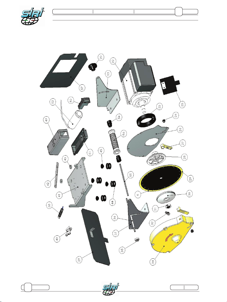
Pos. Q.ty Descrption MaxiBella 75 MaxiBella 105
CODICE CODICE
1 1 tank 12-41 12-41
2 6 Foot/square holder xing knob 1058 1058
3 4 Plastic cap for foot 12-33 12-33
4 1 Complete le hand square assembly 12-60C 12-60C
5 4 Feet 7295 7295
6 1 Square for diagonal 107110 107110
7 1 Lateral extension OPTIONAL 12-65 12-65
8 1 Le hand cutting table 10-13 10-13
9 1 Rubber plug 1041 1041
10 2 Lateral upright 5-0011 5-0011
11 1 Water pump 734 734
12 1 Motor guide 5-1001 5-1000
13 1 Sliding prole 5-1050 5-1050
14 2 Pipes for sliding prole 5-1031 5-1031
15 1 Protractor 12-09 12-09
16 1 Knob for protractor 979 979
17 1 Square 12-06F 12-06F
18 1 Complete right hand square assembly 12-08F 12-08F
19 1 Cable sheath 12-85 12-85
20 3 Knob, D.50 M8 12-32 12-32
21 1 Right hand cutting table 10-03 10-03
22 1 Motor 230/50 2P 5-0020 5-0020
23 1 Bladecover spacer 28-71 28-71
26 1 Disk guard 107000 107000
27 2 water channel for disc cover 107007 107007
28 1 blade holding ange
29 1 D.250 blade 103 103
30 1 blade xing ange
31 1 Disk xing nut M 20 sx M 20 sx
32 1 water pipe connection 7014 7014
34 1 blade cover 107004 107004
35 1 Plastic anti-rotation plaque 12-25 12-25
36 1 Tie-rod 12-24 12-24
37 1 Le hand motor support 5-0041 5-0041
38 1 Traction spring 5-0101 5-0101
39 1 Rear rubber water seal 5-0108 5-0108
40 1 Buttery tap 28-40 28-40
41 1 Sliding motor carriage 5-0042 5-0042
42 1 Carriage stopping plaque 12-57 12-57
43 2 Eccentric pin 12-45 12-45
44 4 Pulley 5-1227 5-1227
45 4 Pulley spacer 12-29 12-29
49 1 Scatola per interruttore 471INT 471INT
50 1 Switch box 505-11 505-11
51 1 Switch base 471RET 471RET
52 1 Capacitor 727 727
53 1 motor support 5-0040 5-0040
54 2 Knob spacer 107099 107099
55 1 Tie-rod for handle 12-46 12-46
56 1 knob 573-01 573-01
57 1 Lateral water guard (optional) 5-0107 5-0107

34/24
1.0
Maxi Bella 75 Maxi Bella 105
8
Charter::
Page: Release::

7/24
1.0
Maxi Bella 75 Maxi Bella 105
Charter::
Page::
Release::
- Make sure there are no foreign objects in the operating area.
- When there is a risk of being hit by projected or falling parts, both solid or in other form,
use goggles with side shields, as well as helmets and gloves if necessary.
- When handling hot materials, it may be necessary to use gloves or other means of
individual protection, to avoid scorching.
- Wear personal means of protection whenever prescribed.
- Even if the machine is not noisy in itself, means of protection against noise may be
necessary owing to the sound pressure level existing in the environment where it is
installed.
- ELECTRICAL EQUIPMENT
Connection work, starting, maintenance, measurements or adjustments of the electrical
equipment and components must be entrusted to qualied electricians.
When working on live electrical components, strictly observe the provisions in force.
1.4 PICTOGRAPHS CONCERNING THE “OPERATOR QUALIFICATION LEVEL”
A Worker: operator with no specic knowledge, capable of
accomplishing simple tasks on the basis of instructions given
by qualied technicians.
B Driver of lifting and handling gear: operator trained for
driving material and machine lifting and transport gear (the
instructions of the maker of these must be scrupulously
followed) in accordance to the laws in force in the machine
user’s country.
C Maintenance mechanic: qualied technician capable of
running the machine in normal conditions; running it with
guards deactivated using a control with a sustained action;
carrying out adjustments, maintenance or repair work on
mechanical components. Not normally authorised to carry out
work on live electric systems.
1

9/24
1.0
Maxi Bella 75 Maxi Bella 105
Charter::
Page::
Release::
Fig. 1
5
6
3
8
4
2
7
1
2 PRESENTATION
2.1 GENERAL INFORMATION
The Maxi Bella 75 and 105 cutters are designed and built for performing linear,
diagonal and 45° (“jolly”) cuts on ceramic tiles, marble, granite, porcelain stoneware, clinker
and cotto.
The diamond-tipped disc supplied with the machine is suitable for cutting ceramic tiles only;
for all other materials, use specic discs.
The cutter basically consists of the following units (Fig. 1):
1) Sliding motor unit (that can be tilted for “jolly” cuts);
2) Motor;
3) Universal diamond-tipped disc; Maxi Bella 75 anD 105 = Ø 250 mm
4) Supports for sliding unit;
5) Tank;
6) Electrical power supply cable;
7) Feet;;
8) Support table.
2
33/24
1.0
Maxi Bella 75 Maxi Bella 105
8
Charter::
Page::
Release::
8/24
1.0
Maxi Bella 75 Maxi Bella 105
Charter::
Page: Release::
D Maintenance electrician: qualied technician capable of
running the machine in normal conditions, as well as running
it with guards deactivated using a control with a sustained
action; also required to carry out all electrical adjustments,
maintenance and repair work. This person is capable of
working on live switchboards and connector blocks.
E Maker’s technician: qualied technician provided by the
maker to carry out complicated operations in particular
situations, as established with the user. Specialised mechanical
and/or electrical technicians are available according to need.
1.5 PICTOGRAPHS RELATING TO SAFETY
Here below is a list of the safety pictographs used on the machine
and/or in this manual.
A Danger of cuts: this warns involved personnel that the
operation described may expose said personnel to the risk of
hand injuries, if it is not performed in accordance to the safety
standards.
B Danger of electric shock: warns staff involved of the risk
of electric shock if the operation described is not carried out
in compliance with safety regulations.
C Always wear ear defenders: this symbol instructs
operators to use headphones since there is a risk of exposure
to loud noise.
D Always wear safety clothing: this symbol instructs
operators to wear goggles and accident-prevention gloves.
1

10/24
1.0
Maxi Bella 75 Maxi Bella 105
Charter::
Page: Release::
Fig. 2
srl
Viale Dalla Costa, 44- 411222 MODENA (ITALY)
C.P. 468 - Tel. 059/313191 Fax. 059/311362
P.IVA e C.F. 00496310368
http://www.SIRI.mo.it
ART: .................................
Matricola: ..........................
Annodi costruzione: 20......
MOTOR 1 Phase Cod.9A058090PM038
TYPE MR58 N.
HP 1.5 Kw 1.1 S 6-40%
V 230 I.C. F
A 7.2 Cos 0.97
Hz 50 m.p.m 2800
IP 55 C25 F Kg IEC 34-1(1983)
MONTECCHIO MAGG. (VI - ITALY)
COSTRUZIONI ELETTROMECCANICHE
ANNO
07/01
Siri
2.2 CHARACTERISTICS
2.2.1 The machine is designed for industrial uses in normal environmental conditions, as
established by point 1.4 of the EN 60204-1. These conditions refer to machine use.
The denition of limits for the presence of personnel is the duty of the person in charge
of designing the workstation(s) and may call for more restrictive measures.
2.2.2 The machine must be run by personnel that have been trained concerning machine
use and are familiar with the contents of this manual.
2.2.3 The machine operates in manual mode.
2.3 THE NAMEPLATE
An exact description of the model, serial number and year of manufacture of the
machine will facilitate rapid and effective replies by our Customer Assistance Service.
This information can be read on your machine’s nameplate.
NB: for no reason may the information printed on the nameplate be altered.
Apart from the CE mark, the nameplate features (Fig. 2):
- Name and address of the maker
- Type of machine
- Serial number
- CE mark and year of manufacture of the machine.
- Voltage in volts
- Frequency in Hz
- Power draw in Amps
2
11/24
1.0
Maxi Bella 75 Maxi Bella 105
Charter::
Page::
Release::
Fig. 3
1
Fig. 4
3
2
B
A
S
C
4
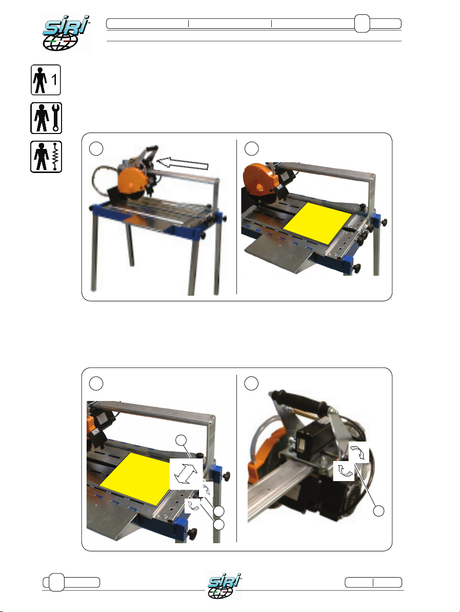
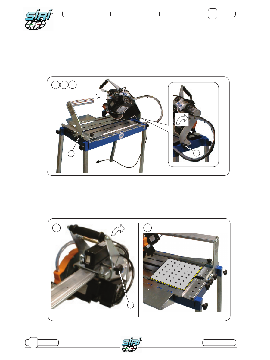
2.4 opeRaTionT
lineaR CuT
linear cuTs are performed as follows:
1) push The sliding carriage To The side opposiTe To The operaTor, unTil iT sTops (fig. 3).
2) puT The Tile on The sheeT meTal Table (fig. 3).
3) Adjust the cutting measurement with the help of the square (S, Fig. 4):
- loosen knobs (A and B) and position square on the basis of the cut to perform;
- tighten knobs (A and B) and clamp square in place.
4) Lock motor unit in its lowered position using knob (C Fig. 4) on right hand side of carriage
2
30/24
1.0
Maxi Bella 75 Maxi Bella 105
8
Charter::
Page: Release::
8.2.1 PERIODIC MAINTENANCE SCHEDULE
Daily maintenance
- After every work shift, remove any tile fragments/scraps which could have built up
during operation.
- Cleaning the tank:
pull out the plug at the bottom of the tank to empty it and clean all the waste and cutting
residue out of it.
Fill the tank with clean water until the pump is submerged.
Weekly maintenance
- Using an aspirator and with the aid of a brush, remove any dirt, fragments or dust which
may have built up in the compartments.
- Maintain water level in the tank.
- Check that none of the machine’s cables is damaged.
- Accurately lubricate guide and all sliding parts using the lubricator supplied with the
machine.
- Clean water pump and cooling system:
if the cooling pump does not bring water to the diamond-tipped disc:
- pull out the plug from the power point;
- check that the regulating cock is open;
- check that the water in the tank completely covers the pump;
- check that the pipe going from the pump to the disc guard is not obstructed;
- check that there are no fragments obstructing the pump lter;
- check that the fan is not jammed and clean any residual dirt off it;
- if the fan is jammed clear it manually so that it can start up.
INTERVENTION Daily Weekly Monthly
Clean the machine At the end of the work shift — —
Clean the tank At the end of the work shift — —
Lubricate the guide — Every week —
Clean the pump — Every week —
Sharpen the disc — — If worn
Replace the disc — — If worn
Check the electric circuit — — Every 6 months
29/24
1.0
Maxi Bella 75 Maxi Bella 105
8
Charter::
Page::
Release::
8 ADJUSTMENT AND MAINTENANCE
Carefully read these instructions, before performing any maintenan-
ce and adjustment on the accessories; this will guarantee safer wor-
king conditions for the personnel involved and a greater reliability
of the interventions made.
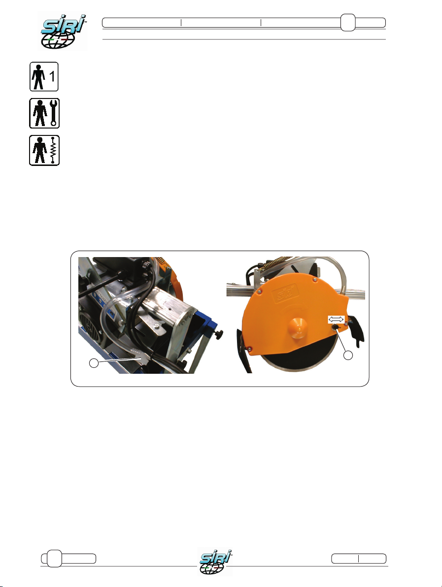
8.1 ADJUSTMENT
Adjusting ow of water to disc
Flow of water to disc can be adjusted by acting on the tap (A).
The direction of the water ow can be controlled by loosening the knobs on either sides (B)
and moving the ow to the right or the left, according to whether you wish to direct the water
onto the disc or onto the piece to be cut (Fig. 19).
8.2 MAINTENANCE
When servicing, observe the following rules:
- Maintenance operations must be effected by qualied and authorised personnel only;
- Make absolutely sure that the electricity supply is isolated, in order to prevent any
accidental restarting.
- After turning off the machine, wait 5 minutes for the motor to cool down;
- make sure the work environment is suitable and equipped with the items needed;
Correct periodic maintenance will maintain your machine in perfect working order.
Apart from periodic maintenance on the various accessories, keep the machine and
surrounding area clean and tidy.
Fig. 19
B
A
13/24
1.0
Maxi Bella 75 Maxi Bella 105
Charter::
Page::
Release::
Fig. 7
1 2
A
A
3
Fig. 8
1
A
2
45° CUTS (“JOLLY” CUTS)
45° (Jolly) cuts are performed as follows (Fig. 7):
1) Loosen xing knobs (A) of sliding bar.
2) Turn motor unit counter-clockwise until it stops.
3) Firmly screw xing knobs (A) at the ends of the machine.
4) Proceed as for linear cuts.
ReCTangulaR CuT
ReCTangulaR CuTS aRe peRfoRMeD aS followS:
1) looSen fixing knoB (a) of MoToR uniT in oRDeR To fReely TilT DiSC To anD fRo.
2) plaCe Tile againST SquaRe wiTh glazeD SiDe faCing Down.
dove vogliamo ottenere il rettangolo;
2

14/24
1.0
Maxi Bella 75 Maxi Bella 105
Charter::
Page: Release::
Fig. 8
34
3) With the machine off, place the diamond-tipped disc above the tile in the position in which
the rectangle will be cut.
4) Start motor and lower disc to perform a through-cut on the tile, forming one side of the
rectangle.
5) Repeat cut for three remaining sides of rectangle.
2.5 TECHNICAL DATA
The machine has these basic features:
Technical data Maxi Bella 75 Maxi Bella 105
Power supply 230 V - 50 Hz 230 V - 50 Hz
Power draw 7.5 A 7.5 A
RPM 2800 2800
Capacitor 25 Uf 25 Uf
IP protection rating 55 55
Insulation class F F
Linear cut 75 cm 105 cm
Jolly cut 75 cm 105 cm
Diagonal cut 50x50 cm tile 74x74 cm tile
Altezza taglio 5.5 cm 5.5 cm
Diamond disc Ø 250 smooth crown 250 smooth crown
Wheight 51 Kg 72 Kg
Overall dimensions 1050x520x500 cm 1500x550x560 cm
2
27/24
1.0
Maxi Bella 75 Maxi Bella 105
7
Charter::
Page::
Release::
7 STARTING AND STOPPING
7.1 FIRST START
After installing the machine, a few preliminary checks must be made before use.
Before starting, read this manual with care.
Should the Purchaser wish to carry out these operations autonomously, this manual must
be read beforehand with great care in order to become conversant with the purpose and
effect of the commands given
7.1.1 Supply activation
7.1.1.1 Electricity:
- Power up the machine by icking the lever on the power switch to ‘1’ (ON).
- Insert the machine’s plug into the socket.
Ensure that all guards are in place and in working order.
Interrupting the electricity supply, even for a short lapse of time, will immediately interrupt
machine operation.
When power is restored, the machine does not start up immediately but only after the switch
is icked to “1”.
7.1.1.2 Water pump:
- Fill the tank and check that the pump inside is completely submerged.
Check that the water in the tank is always clean for correct
operation of the machine.
7.2 EXPECTED USE OF THE MACHINE
The machine has been designed for being run by one operator
only. Other operators must keep at a safe distance from the machine.
This manual suits for next models
1
Table of contents
Other SIRI Cutter manuals


