Borkey 396 euroline Instruction Manual
Different possiblities of fixing the keys in the reversible vices
Side 1 Fixing of the keys at the base. For keys with a cutting depth of up to .5mm.
Standard cross keys up to a length of 120 mm.
Side 2 Fixing the keys at the base. For keys with a cutting depth less than 3.6 mm.
Cross keys with ring.
Side 3 Fixing of the keys at the base. For keys with a cutting depth less than 2.0 mm.
Side 4 Fixing of the keys in the profile (top side or bottom side of the keys).
W
orking instructions
Make sure, that both vices (for the pattern and the key blank) always indicate the
same position (side number).
For changing the position (side number) loosen knurled-nut (15) (pict.3) first and lift
the complete vice in order to turn to the required position (side number).
Keep vices always clean.
After turning of the vices push vices downwards and re-tighten knurled nut.
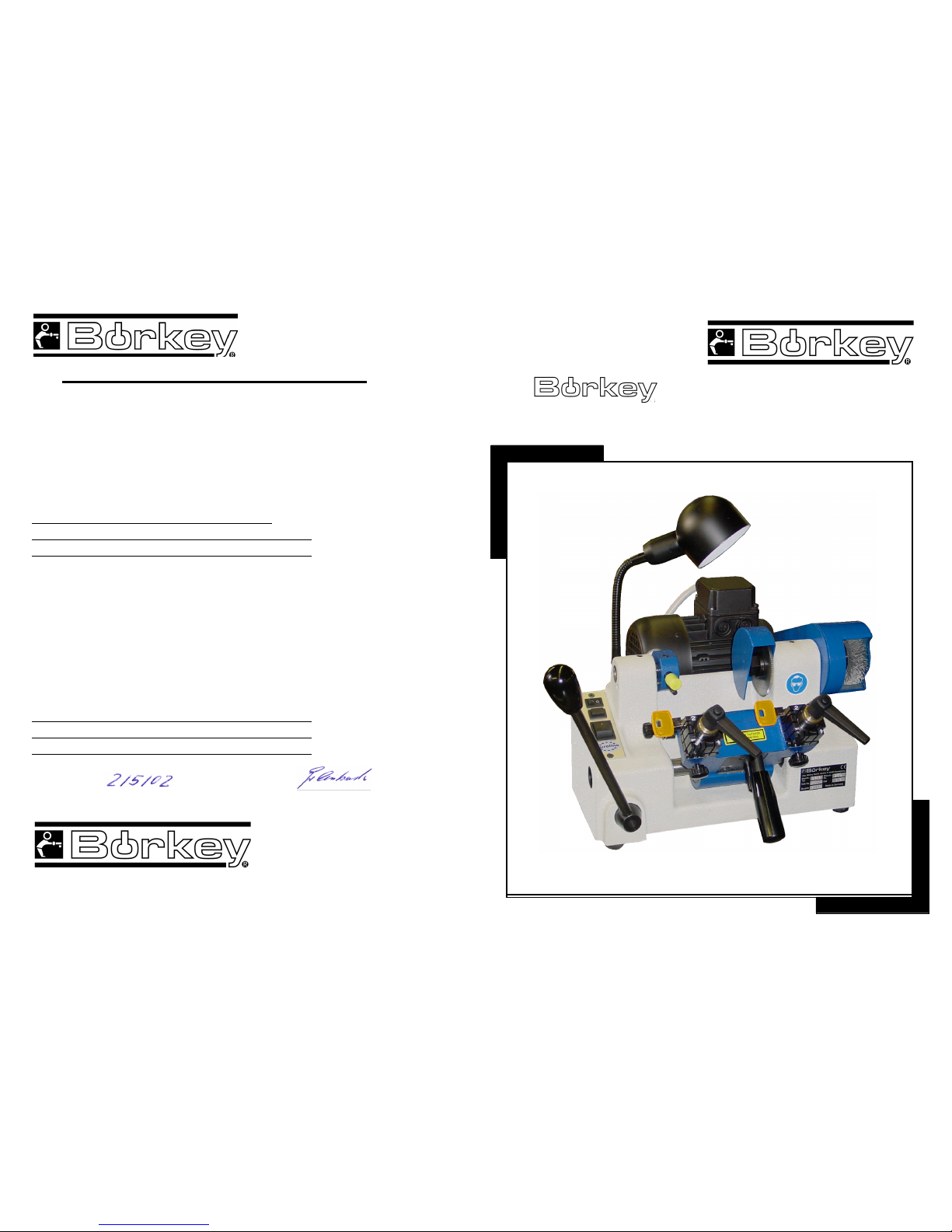
Semi automatic key cutting machine
Börkey 396 euroline
for cutting cylinder-,car- and cross keys up to 100 mm length
Main characteristics
• Copying every cutting angle without changing the cutter
• abraison parts are interchangeable
• maintenance-low cutting spindle fitted in a ball-bearing
• feeler fine adjustment
• when operating the carrige the cutter will start- and stop
running automatically
T
echnical Data
Input: 134 w
Voltage: 230v
Frequency: 50 cycles
Weight: 29 kgs.
Dimensions: 35 x 33 x 25 cms.
Sound level: 77 dB (A)
Protection fuse: 6 A
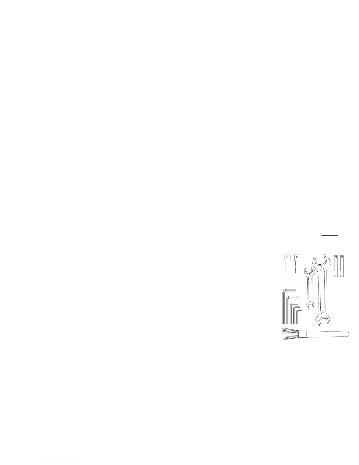
Standard tool kit equipment order no. Pict. 1
1. 2 check up keys 9954-204-008
2. 1 O.E. spanner SW13/10 9000-204-002
3. 1 O.E. spanner SW22/19 9000-204-001
4. 2 flat bars with cut-out section 9994-W10-007
7. 1 allen key SW5 9000-022-005
8. 1 allen key SW4 9000-022-004
9. 1 allen key SW3 9000-022-003
10. 1 allen key SW2,5 9000-022-002
11. 1 allen key SW2 9000-022-001
12. 1 brush 9000-021-001
1.
2.
3. 4.
11.
10.
9.
8.
7.
12.
12 1
Notes to the instructions of use
Read the instructions for use very carefully and pay attentions to their notes.
The instructions of use section contains important information on how to operate
the key machine safely and accurately.
In addition to the operating instructions the respective national rules + regulations for
Accident prevention and environmental protection must also be observed.
T
he instructions must always be at hand at the place
of use of the machine !
Dully use of the machine
Only use the key machine for cutting cylinder-, car- and cross keys.
Using the machine for purpose other than those mentioned above is considered
Contrary to it designated use.
The manufacturer cannot be liable for any damage or injury resulting from misuse.
The risk is entirely with the user.
Operating the machine within the limits ofis designated use also involves observing the
Instructions set out in the operating manual and complying with the maintenance directives.
Fundamental safety instructions
Any work on or with the machine must be executed by competent personnel.
Staturory minimum age limits must be observed!
Mount the machine to a dry rigid surface offering the correct working height for the operator.
The machine must not be used outdoors or in areas with the danger of exlosive or
inflammable material.
Before using the machine check that it complies (see sticker on machine) with the mains
voltage.
Mains connection must only take place through a fixed, approved and protected socket.
Operte the machine only when all protective and safety-oriented devices are in place and fully
functional.
Always stop the machine motor after use or leaving the machine.
Always disconnect machine from mains supply when repairing or doing routine maintenance.
Repairing of the machine must only be performed by trained and instructed staff (only use
genuine replacement parts).
Work on electrical equipment on the machine must only be performed by a skilled electrician.
Connecting cables
• Check regulary for obvious damage, defects or ageing
• Keep away from squeezing- and shrearing places
• Never use machine with defective cables
2
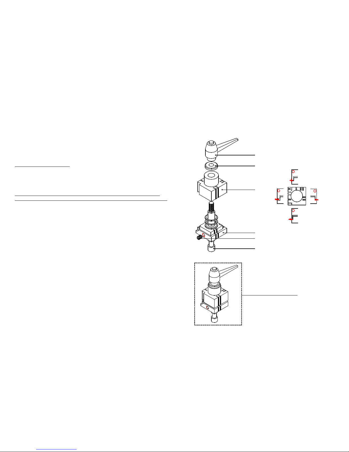
4 – way reversible vices
4 possibilities of fixing the key at the vice
11
Reversible vice complete
1
2
4
4
12
3
3
9396-000-059
9396-000-034
9396-000-033
9396
-
000
-
032
9000
-
004
-
011
9396-000-031
Special warning
• never try to hold cutter unless machine is disconnected
at mains!
• never grip- or remove keys with cutter still running !
• always wear safety goggles !
• make sure long hair is tied back or otherwise secured, never
wear neck ties or loose fitting clothes !
• if trouble occurs switch off and unplug the machine
immediately or disconnect fuse !
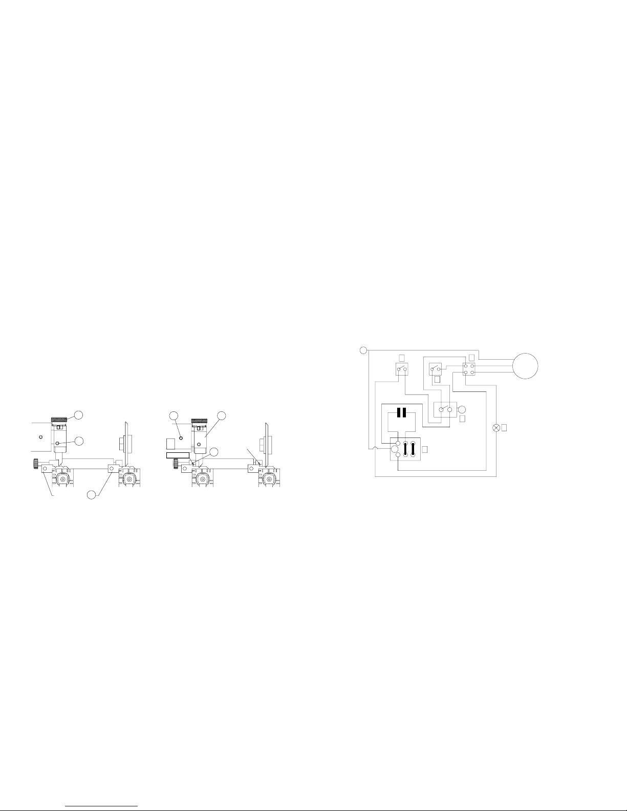
Pict. 2 Wiring diagramm with work-light
mains
supply
6
4
2
1
3
5
body
PE
PE
capacitor
1 = push-bottom switch wire brush 9396-000-053
2 = switch work-light 9393-000-054
3 = main switch 9396-000-052
4 = stopp switch 9396-000-065
5 = work-light 9396-000-056
6 = motor 9396-000-062
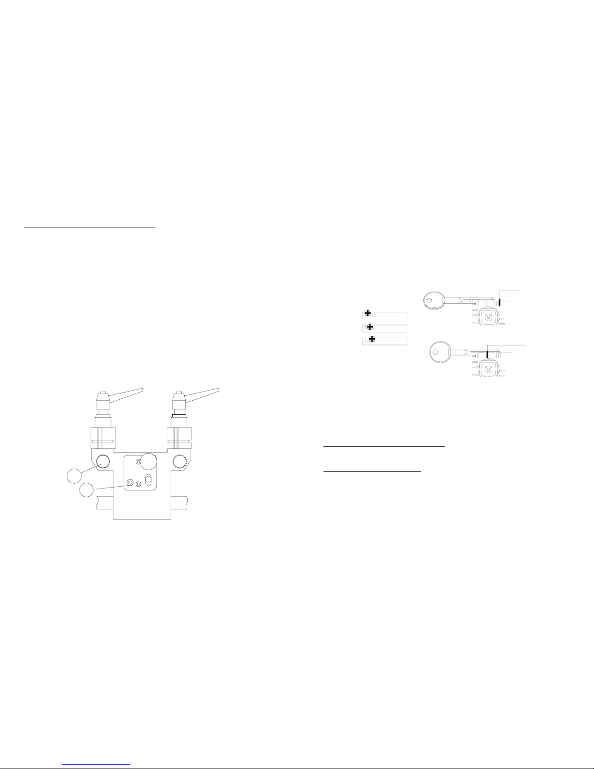
Checking and adjusting
Cutting depth (Pict. 9 )
Fasten check-up-keys ( 12 ) in the left- and right-hand vice. Release carriage so that cutter
and feeler are touching the edges of the check-up-keys.
Readjustment of the cutting depth with knurled nut ( 2 ) (see page 5 ).
Lateral distance (see page 10)
Feeler - cutter
Fasten check-up-keys ( 12 ) in the left- and right-hand vice. For location push check-up-keys
firmly against left hand side of the vices.
Release carriage so that cutter and feeler are exactly in the cuts of both check-up-keys.
Readlustments: Loosen the screw ( 13 ) of the feeler base (3).
es Fühlerhalters ( 3 ).
Move the feeler base until cutter and feeler are exactly in the cuts of
both check-up-keys. Tighten screw (13) again.
- the alignment gauge lever
Rotate the alignment gauge lever until the flat edges of the levers locates against the
shoulders of both check-up-keys.
Proof: Insert a thin piece of paper between shoulder of check-up-keys and
alignment gauge levers. Both pieces of the paper should be stuck.
Readjustments: Loosen screw (14) on the alignment gauge levers and push levers
against shoulders of the check-up-keys. Tighten screw (14) again.
Pict. 9 Bild 10
+
-+
-
3
13
14
Check-up-key
Check-up-keyl
12
Check-up-keys
2
16
X
X screw for adjusting
the lateral disance
10 3
Maintenance
Clean machine regulary with brush to avoid
swarf accumulating.
Do not use compressed air to clean machine !
If after long pressure of main carriage spring becomes weak it is adjustable
by turning screw ( 17 ) at the front of the main carriage (use allen key SW5).
Lubricate with good quality machine oil every 4 months (earlier if required) the
following parts:
• carriage shaft
• start lever for slide carriage
(see parts shown marked on page 5 )
Do not grease the cutter-spindle !
Keep pulley wheel and drive belt always free
of grease !
Pict. 3 Tension of carriage spring
-
+
17
15
4
Cutting cross type keys up to 100mm (Pict.7)
Depending of the length of the cross keys use the flat bars as a shoulder stop to
locate the keys. Place the flat bars in the slot-cuts of the left hand side of the vices.
After gripping of the keys push the flat bars backwards.
For location of cross keys with a ring push pattern and key blank with the ring firmly
against the left hand face of the vices.
Place a flat bar into one of the slots of the right hand side of the vices to prevent the
top-part of the vices from moving sideways.
Pict. 7 Pict. 8
flat bars with cut-out
section
flat bars
Starting operation key cutting
Switch machine on a rocker-switch ( 11 ), position front part of the switch pushed
(light is on).
To release the carriage to the feeler and cutter push carrige little further down and pull
trigger release below the carriage-handle.
Be aware of the spring tension and hold slide carriage carefully at carriage know and
gently engage the feeler to the first cut of the pattern at the key bow.
The cutter will start running automatically.
By usingthe carriage start-lever ( 10 ) copy the key from the shoulder to the tip of the key.
After cutting push slide carriage back to „park-position”.
The cutter will start automatically.
Use wire brush for deburring the key.
For using the wire brush please keep switch ( 1 ) pushed.
9
2
1
Setting up machine for cutting a key
Cutting keys with a shoulder for location (Pict. 5 )
Fasten the pattern of the key to be reproduced firmly in the left hand vice with the
shoulder of the key appr. 2 mm away from the left hand side of the vice. Rotate the
alignment lever until the flat edge of the left hand alignment guide locates against the
shoulder of the pattern key. Fasten the key blank in the right hand vice with the shoulder
of the key blank pushed firmly up to the right hand alignment gauge lever.
When both key and key blank are correct located in the two vices rotate the alignment
lever back out of the way. For location of keys with shoulder on both sides, push pattern
and key blank firmly against the right hand side of the vices.
In order to prevent cutting into the vices when copying small keys or keys with
deep-cuts (below 3.60 mm) use small round pins.
Place the pins in the vices behind the back of the pattern and key blank.
Clean the vices and the key support regularly with the brush to avoid swarf
accumulating.
Pict. 5
+-
Cutting keys without shoulders for location (Pict. 6)
The correct positioning of this type of key is made possible by using the flat bars
of the tool kit as tip-stops. Place these bars in the left or right hand slot-cut in both
vice-faces (both pattern and key blank should be in the same slot position).
Push pattern and key blank up to each bar and tighten the keys in the vices.
Pict. 6
flat bars
8
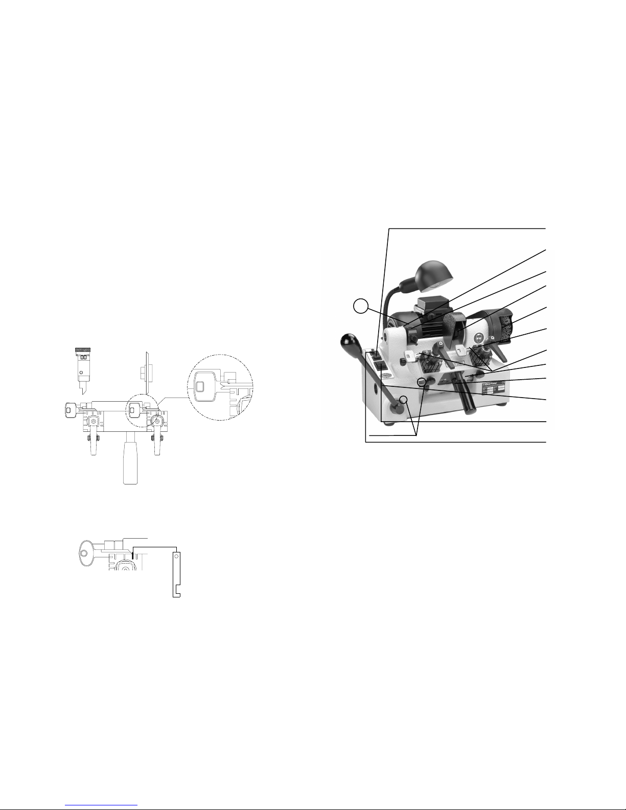
Pict. 4 Main functional parts
1. push-bottom switch
wirebrush
2.adjustment
cutting depth
3.feelerbase
4.location
cutter
5.location
wirebrush
6. gripping
vices
7. alignment gauge lever
8.slidecarriage
9.triggerreleasefor
slidecarriage
10.startlever-
slidecarriage
11.on/off switch
12.switchlight
Description of main functional parts
1. Push-bottom switch for wire-brush
For using the wire-brush push switch ( 1 ).
2. Adjustment cutting-depth
to decrease cutting depth:
Right turn (+) = loosen set screw (16). Turn the knurled nut (2) to the right
(the feeler will move forwards).
Left turn (-) = loosen set screw (16). Turn the knurled nut (2) to the right
(the feeler will move backwards).
One stroke on the knurled nut means 0.05mm. Retighten the set screw when
the required depth is reached.
3. Feeler base
The feeler base ( 3 ) holds the adjustable feeler. Adjustment please see page 10.
lubricate here
5
16

4. Changing cutter
Switch machine off at mains. Remove cutter guard. Loosen
cutter nut by pulling spanner towards you, to Stopp the spindle turning,
put the 5 mm bar from tool kit in the hole of the cutter axle.
Fit the new cutter and tighten cutter nut by pushing the spanner to the left.
Check the adjustment of the machine (see page 10).
A
ttention!Remove all tools from cutter spindle
before turning the machine back on
atmains.
5. Changing wire brush
Switch machine off at mains.
Disconnect belt cover.
Loosen nut of the brush with spanner ( SW 19 ).
Stop the spindle turning by using the ( 5mm ) bar.
Pull the brush out of the cutter axle and install new wire brush.
Retighten the nut.
A
ttention!Remove all tools from cutter spindle
before turning the machine back on
atmains.
6. Gripping vices
Gripping vices/jaws to hold keys and the spezial gripping devices.
Left vice to hold the sample- and right vice to hold the key blank.
7. Alignment gauge lever
The levers are used to correctly position key and key blank.
Preparing and checking see pages 8 and 10.
8. Slide carriage
Slide carriage for holding the vices – with spring tensions. trigger release ( 9 )
and alignment pages 8 and 10.
9. Trigger release for slide carriage
Safety device to hold the slide carriage ( 8 ) in “park-position”
for working on the vices (gripping of keys etc.)
Sie kann nur betätigt werden, wenn die Anschlaghebel ( 7 ) in
der Grundstellung anliegen.
10. Start lever slide carriage
Movement of the slide carriage to the left and/or to the right
by using the start-lever ( 10 ).
11. On/Off rocker-switch machine
Position: back part of the switch pushed - light is off - machine is off
Position: front part of the switch pushed – light is on - machine is on
12. On/Off switch work-light
Position 0 -work light is off
Position 1 -work light is on
9396-000-022 alignment gauge lever
9396-000-030 feeler
9396-000-032 lower part of the vice
9396-000-033 upper part of the vice
9396-000-034 brass-ring
9396-000-052 rocker-switch ( main switch machine )
9396-000-053 push-switch ( wire brush )
9396-000-054 switch ( work light )
9396-000-055 black-knob at start-lever slide carriage
9396-000-056 work light
9396-000-057 spare bulb - 25 w.
9396-000-058 cutter guard
9396-000-059 clamping lever ( gripping vice )
9396-000-060 knurled screw ( gripping vice )
9396-000-061 handle (for slide carriage)
9396-000-062 motor
9396-000-063 belt
9396-000-092 belt (new from M.-No.1088)
9396-000-064 wire brush
9396-000-065 stop switch ( slide carriage )
7
6

fault finding
Machine does not work
• Check mains plug is in socket and mains supply is on.
• Machine is not switched on at rocker-switch ( 11 ).
• Stop-switch at the slide carriage is defective.
Attention :Work on electrical equipment on the machine must only be performed
by a skilled electrican.
Power is on but cutter will not rotate (machine is connected to power
supply)
• Disconnect belt cover and brush.
Check belt is connected or defective.
Check if pully wheel will turn.
Check if motor axle will turn.
Belt is defective
• Change belt. Use only genuine belts.
Loosen 4 nuts under body of machine and reposition motor until belt fits on both
pully wheels. Push motor back to old position and ritighten nuts.
Not possible to turn the motor- and/or cutter-axle
• Please contact our technical-service.
W
or
k
-light does not work
• Check if plug is in socket and turned on.
Check lamp balast.
W
or
k
-light is defective
Change the bulb only when machine is switched off.
Cutter is noisy, bad cutting quality or machine is out of adjustment
• Change cutter (see page 6) Check adjustment of machine (see page 10).
Imossible to release the slide-carriage to feeler and cutter
Please check if alignment gauge axle is at „park-position“.
If yes, please contact our technical-service.
In case of any other faults please contact our sales department.
T
ele.: 02332/7006-0
13
EC Conforming-Declaration
according to the EC-regulation machines 89/392/EWG, supplement II A
We August Börkey Nachf. GmbH
Geerstraße 4-12
D – 58285 Gevelsberg
Telefon 02332/7006-0
Telefax 02332/700522
herewith declare that the construktion of the key cutting machine
Modell: key cutting machine
Type: 396 Euroline
Serial-Number:
is in accordance with the following rule:
EC-regulation machine version 91/368
Used harmonized standards are especially:
EN 292 T.1 und T.2;
EN 294;
EN 349;
EN 60204
Name: Erlenbach
Surename: Manfred
Position: Managing Factory Director
Gevelsberg, the __________ _____________
signature
GEERSTRASSE 4 - 12
58285 GEVELSBERG
TELEFON 02332/70 06-0
TELEFAX 02332/70 06 22
1/01/100/D
396 euroline
INSTRUCTIONS FOR USE
Table of contents
Other Borkey Cutter manuals


