Sirona Cerec User manual
léÉê~íáåÖ=fåëíêìÅíáçåë
MRKOMNR
`bob`=o~Çáç=aÉîáÅÉ
kÉï=~ë=çÑW==
båÖäáëÜ
=
båÖäáëÜ
Operating Instruct ions

65 45 177 D3492
2D3492.201.09.01.02 05.2015
Table of contents Sirona Dental Systems GmbH
Operating Instructions CEREC Radio Device
Table of contents
1General data............................................................................................................. 4
1.1 Dear Customer,............................................................................................. 4
1.2 Contact information ....................................................................................... 4
1.3 General information about this operating manual ......................................... 5
1.4 Structure of the document............................................................................. 5
1.4.1 Identification of danger levels........................................................... 5
1.4.2 Formats and symbols used .............................................................. 6
2Safety instructions .................................................................................................... 7
2.1 Important information for the user ................................................................. 7
2.2 FCC and IC declarations............................................................................... 8
2.3 EC Declaration of Conformity........................................................................ 9
3Product description................................................................................................... 10
3.1 Main components of the product................................................................... 10
3.1.1 Controls............................................................................................ 10
3.1.2 LED displays .................................................................................... 11
4Technical data.......................................................................................................... 12
5System description ................................................................................................... 13
5.1 CEREC system ............................................................................................. 13
5.2 System components...................................................................................... 14
5.3 Main function................................................................................................. 15
5.4 Network unit .................................................................................................. 16
6Networking ............................................................................................................... 18
6.1 CEREC Radio Device network overview ...................................................... 18
6.2 Creating a network ........................................................................................ 18
6.2.1 Creation............................................................................................ 19
6.2.2 Isolated network unit ........................................................................ 19
6.2.3 Permanent network .......................................................................... 19
6.2.4 Installation ........................................................................................ 19
6.2.5 Maximum size .................................................................................. 19
6.3 Network creation failures............................................................................... 19
6.3.1 Isolated network unit ........................................................................ 19
6.3.2 Multiple networks created ................................................................ 20
6.4 Extending the network................................................................................... 20
6.4.1 Adding a new network unit ............................................................... 20

65 45 177 D3492
D3492.201.09.01.02 05.2015 3
Sirona Dental Systems GmbH Table of contents
Operating Instructions CEREC Radio Device
båÖäáëÜ
6.4.2 Reducing the network...................................................................... 21
6.5 Resetting to factory defaults......................................................................... 22
6.6 Network unit states....................................................................................... 22
6.6.1 State definitions............................................................................... 22
6.6.2 Transitions between states.............................................................. 23
6.7 Radio characteristics .................................................................................... 24
6.7.1 Frequency spectrum........................................................................ 24
6.7.2 Channel control ............................................................................... 24
6.7.3 Channel switching ........................................................................... 24
7Data transmission.................................................................................................... 25
7.1 Stationary data transmission ........................................................................ 25
7.2 Network routing ............................................................................................ 26
7.3 Multiple streams ........................................................................................... 27
7.4 Simultaneous access ................................................................................... 28
7.5 Interrupted transmission............................................................................... 29
7.6 Increasing the range..................................................................................... 30
8Disposal................................................................................................................... 31

65 45 177 D3492
4D3492.201.09.01.02 05.2015
1General data Sirona Dental Systems GmbH
1.1Dear Customer, Operating Instructions CEREC Radio Device
1General data
1.1 Dear Customer,
General description
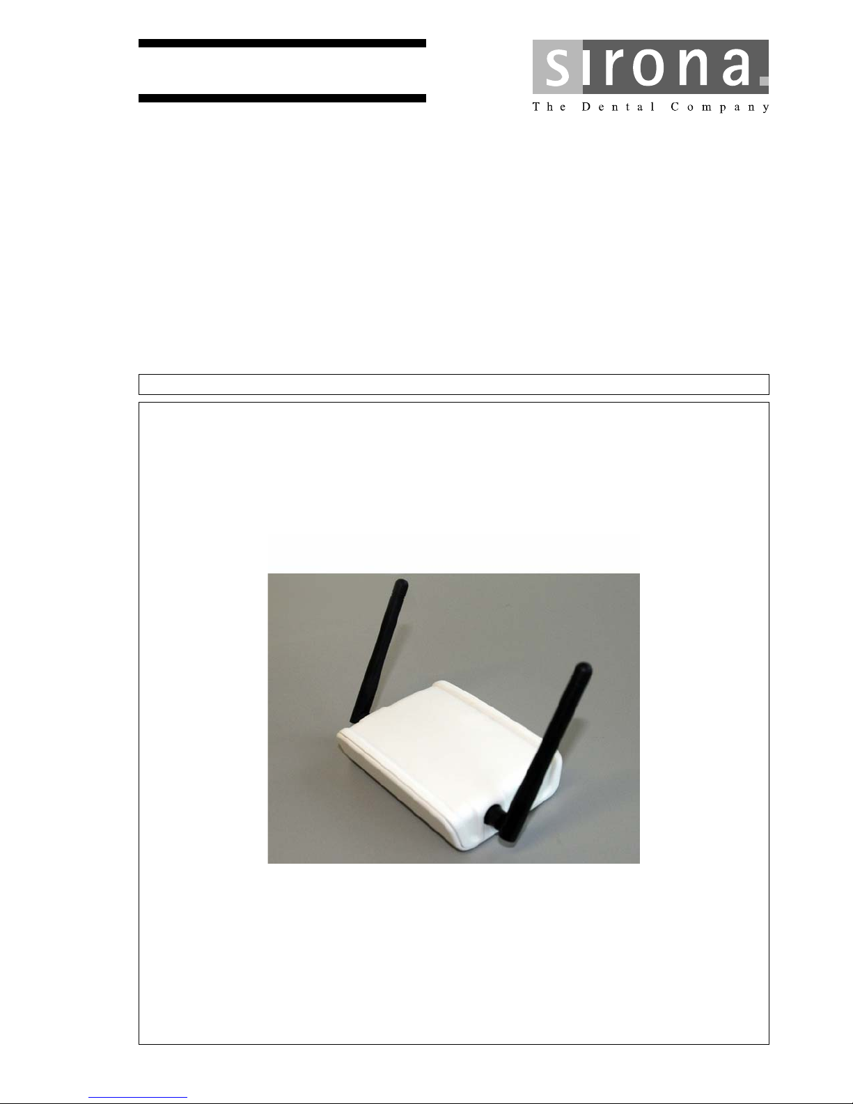
Thank you for purchasing your CEREC Radio Device from Sirona.
This CEREC Radio Device allows you to set up a wireless network for
communication between acquisition units and milling units.
The CEREC Radio Device (REF 65 43 891 D3492) is a powerful, wireless
100 Base-T Ethernet transmission system, by means of which periphery
devices can establish a wireless network, or which can access it via a
cable network. The CEREC Radio Device works on the 2.4 GHz ISM
frequency band and complies with FCC, IC, and EU regulations.
The CEREC Radio Device can be installed with ease and does not
require any special drivers. It can be used with most computers and
operating systems.
This equipment manual contains the technical data for the Radio Device
and operating instructions.
Should problems arise during the course of installation, or when in
operation, which cannot be resolved using the information in this
equipment manual, please refer to your local dealer’s customer service
department or to Sirona (see “Contact information [ → 4]”).
Improper use and handling can create hazards and cause damage.
Please therefore read and follow these operating instructions carefully.
Always keep them within easy reach.
Also pay attention to the safety instructions to prevent personal injury and
material damage.
Your Team
Your
CEREC Team
1.2 Contact information
Worldwide customer service
Customer service center In the event of technical queries, please use our online contact form at
www.sirona.com. In the navigation bar, go to the menu commands
"CONTACT"
/
"Customer Service Center"
and then click the
"CONTACT
FORM FOR TECHNICAL QUESTIONS"
button.
Manufacturer's address (worldwide)
Manufacturer's address Sirona Dental Systems GmbH
Fabrikstrasse 31
64625 Bensheim
Germany
Trademark
Phone: +49 (0) 6251/16-0
Fax: +49 (0) 6251/16-2591
e-mail: [email protected]
www.sirona.com

65 45 177 D3492
D3492.201.09.01.02 05.2015 5
Sirona Dental Systems GmbH 1General data
Operating Instructions CEREC Radio Device 1.3General information about this operating manual
båÖäáëÜ
1.3 General information about this operating manual
Observe theOperating Instructions
Observe the Operating Instructions Please familiarize yourself with the unit by reading through these
Operating Instructions before putting it into operation. It is essential that
you comply with the specified warning and safety information.
Storage of documents, online portal, help
Keep documents safe Always keep the Operating Instructions handy in case you or another
user require(s) information at a later point in time. Save the Operating
Instructions on the PC or print them out.
If you sell the unit, make sure that the Operating Instructions are included
with it either as a hard copy or on an electronic storage device so that the
new owner can familiarize himself with its functions and the specified
warning and safety information.
Online portal for technical documents We have set up an online portal for the Technical Documents at http://
www.sirona.com/manuals. From here, you can download these
Operating Instructions along with other documents. Please complete the
online form if you would like a hard copy of a particular document. We will
then be happy to send you a printed copy free of charge.
Help If you reach an impasse despite having thoroughly studied the operating
instructions, please contact your dental depot.
1.4 Structure of the document
1.4.1 Identification of danger levels
To prevent personal injury and material damage, please observe the
warning and safety information provided in this document. Such
information is highlighted as follows:
Tip: Information on making work easier.
DANGER
An imminent danger that could result in serious bodily injury or death.
WARNING
A possibly dangerous situation that could result in serious bodily injury
or death.
CAUTION
A possibly dangerous situation that could result in slight bodily injury.
NOTICE
A possibly harmful situation which could lead to damage of the product
or an object in its environment.
IMPORTANT
Application instructions and other important information.
65 45 177 D3492
6D3492.201.09.01.02 05.2015
1General data Sirona Dental Systems GmbH
1.4Structure of the document Operating Instructions CEREC Radio Device
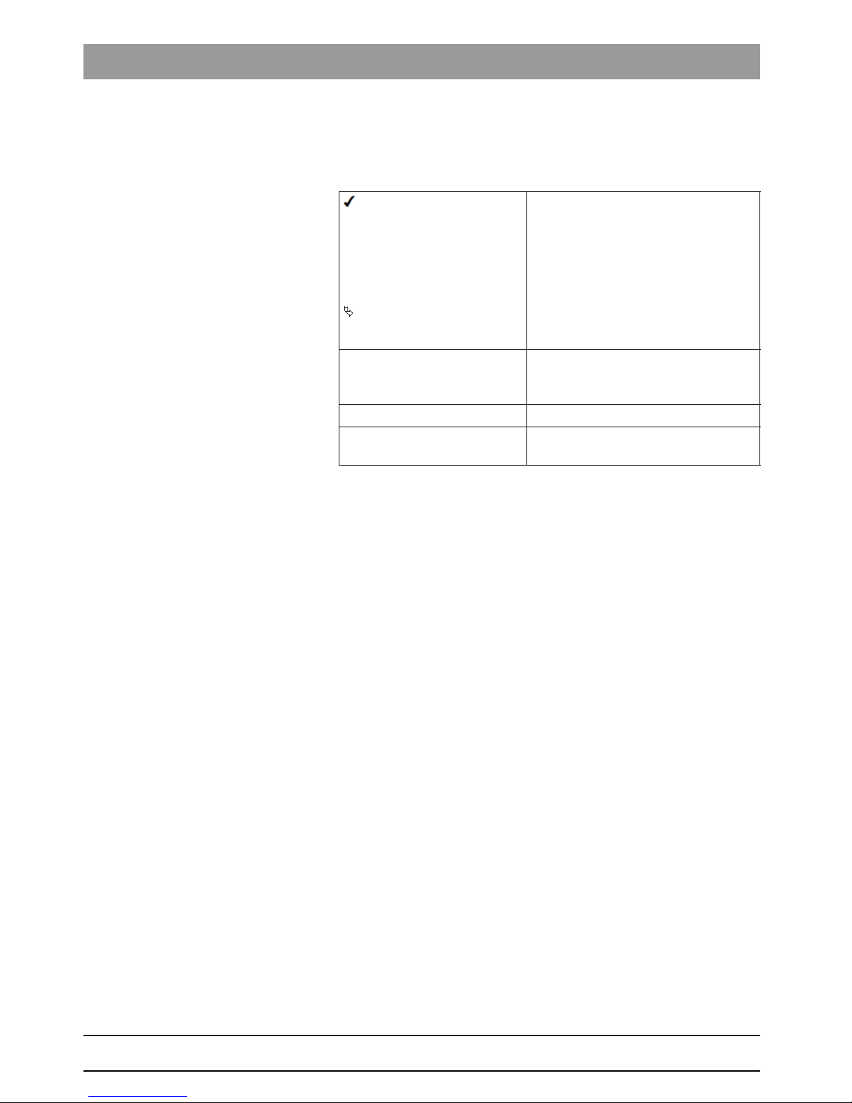
1.4.2 Formats and symbols used
The formats and symbols used in this document have the following
meaning:
Prerequisite
1. First action step
2. Second action step
or
➢ Alternative action
Result
➢Individual action step
Prompts you to do something.
see "Formats and symbols
used [ → 6]"
Identifies a reference to another text
passage and specifies its page
number.
● List Designates a list.
"Command/menu item" Indicates commands, menu items or
quotations.

65 45 177 D3492
D3492.201.09.01.02 05.2015 7
Sirona Dental Systems GmbH 2Safety instructions
Operating Instructions CEREC Radio Device 2.1Important information for the user
båÖäáëÜ
2Safety instructions
2.1 Important information for the user
The CEREC Radio Device does not require any maintenance or special
care. Observe the following safety instructions:
Safety instructions
Do not operate the unit in the vicinity of strong electromagnetic fields.
Observe the operating temperature range specified in the section
“Technical data [ → 12]”. Prevent overheating!
Protect the unit against moisture and dust.
Clean the unit using only a soft cloth and a mild cleaning agent. Do not
use any water or liquid cleaning agents.
Do not insert any objects in the openings of the unit, unless this is
explicitly instructed in this document. This could damage the unit.
Do not open the CEREC Radio Device! It does not contain any parts that
could be serviced, replaced, or repaired by customers or by any
unauthorized maintenance personnel.
Opening the unit can cause damage to the electrical components. In this
case, proper functioning of the unit can no longer be guaranteed!

65 45 177 D3492
8D3492.201.09.01.02 05.2015
2Safety instructions Sirona Dental Systems GmbH
2.2FCC and IC declarations Operating Instructions CEREC Radio Device
2.2 FCC and IC declarations
Fragment nicht übersetzen
Compliance statement
This device complies with part 15 of the FCC Rules and to Industry
Canada’s license-exempt RSSs.
Operation is subject to the following two conditions:
(1) this device may not cause harmful interference, and
(2) this device must accept any interference received, including
interference that may cause undesired operation.
Le présent appareil est conforme aux CNR d‘Industrie Canada
applicables aux appareils radio exemts de licence. L‘exploitation est
autorisée aux deux conditions suivantes :
(1) l‘appareil ne doit pas produire de brouillage, et
(2) l‘utilisateur de l‘appareil doit accepter tout brouillage radioélectrique
subi, même si le brouillage est susceptible d‘en compromettre le
fonctionement.
Warning
Changes or modifications not expressly approved by the party
responsible for compliance could void the user’s authority to operate the
equipment.
This in particular is applicable for the antenna which has been delivered
with the CEREC Radio Device.
RF Exposure
To comply with FCC RF exposure requirements for mobile transmitting
devices, this transmitter should only be used or installed at locations
where there is at least 20cm separation distance between the antenna
and all persons.
Information to the User
Note: This equipment has been tested and found to comply with the limits
for a Class B digital device, pursuant to part 15 of the FCC Rules. These
limits are designed to provide reasonable protection against harmful
interference in a residential installation. This equipment generates, uses
and can radiate radio frequency energy and, if not installed and used in
accordance with the instructions, may cause harmful interference to radio
communications. However, there is no guarantee that interference will not
occur in a particular installation. If this equipment does cause harmful
interference to radio or television reception, which can be determined by
turning the equipment off and on, the user is encouraged to try to correct
the interference by one or more of the following measures:
● Reorient or relocate the receiving antenna.
● Increase the separation between the equipment and receiver.
● Connect the equipment into an outlet on a circuit different from that to
which the receiver is connected.
● Consult the dealer or an experienced radio/TV technician for help.
This device complies with Industry Canada ICES-003: CAN ICES-3 (B)/
NMB-3(B).
65 45 177 D3492
D3492.201.09.01.02 05.2015 9
Sirona Dental Systems GmbH 2Safety instructions
Operating Instructions CEREC Radio Device 2.3EC Declaration of Conformity
båÖäáëÜ
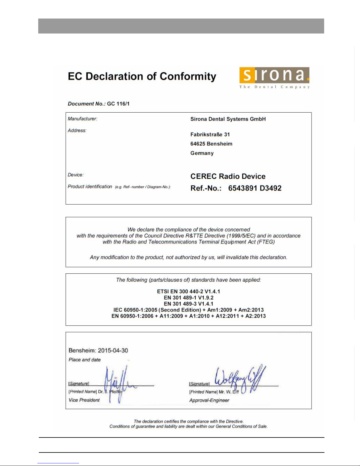
2.3 EC Declaration of Conformity
65 45 177 D3492
10 D3492.201.09.01.02 05.2015
3Product description Sirona Dental Systems GmbH
3.1Main components of the product Operating Instructions CEREC Radio Device
3Product description
3.1 Main components of the product
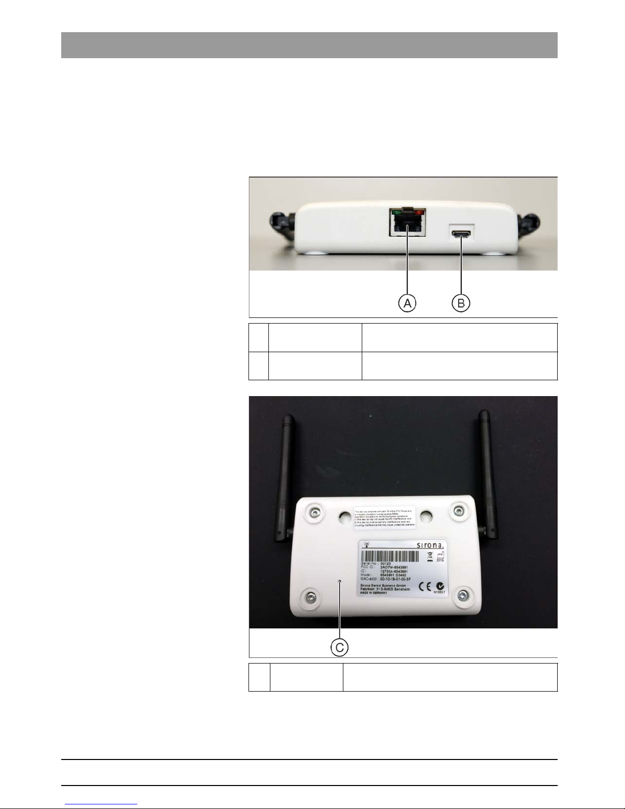
3.1.1 Controls
A Ethernet RJ45 port for Ethernet 100 Base-T with red
and green LED
B DC input Micro-B USB connector for 5 VDC power
supply
C Reset button Opening for pressing the reset button. Use a
pointed object to press the button.

65 45 177 D3492
D3492.201.09.01.02 05.2015 11
Sirona Dental Systems GmbH 3Product description
Operating Instructions CEREC Radio Device 3.1Main components of the product
båÖäáëÜ
3.1.2 LED displays
Two LEDs indicate the condition of the unit. Each LED may have the
following states:
●Off
●Slowly flashing
●Quickly flashing
●On
The table below shows the possible unit states:
State LED color
Orange
LED color
Green
Explanation
Booting Off Off Both LEDs are not yet ready for operation.
Networking Slowly Slowly This state usually only occurs when a new network
is set up.
Isolated Quickly Slowly No network could be created.
Separated On Slowly No network devices are in range.
Connected Off On The unit is working properly and is ready for data
transmission.
Transfer Off Quickly Quick flashing indicates data transfer in process.
Error Quickly Quickly A serious error has occurred. A restart and possibly
a firmware update are required to resolve this.

65 45 177 D3492
12 D3492.201.09.01.02 05.2015
4Technical data Sirona Dental Systems GmbH
Operating Instructions CEREC Radio Device
4Technical data
Dimensions: Approx. 104 x 75 x 24 mm
Weight: Approx. 100 g
Operating temperature: 0 to 40°C
Storage temperature: -25 to 80°C
Power supply: 5 VDC (max. 1.4 W)
Data interface: 100 Base-T Ethernet
Frequency band: 2402 to 2480 MHz
Transmitted power: Max. 10 mW (+10 dBm)
Standards: EN 60950-1:2006 + A12:2011
EN 301489-1/-3
EN 300440-02 V 1.4.1
AS/NZS 4268:2008
FCC: 47 CFR Part 15
RSS-210
Conformity: R&TTE, FCC, and IC
Modulation: GFSK
Multiplexing: Not available
Wireless data rate: 1 Mbit/s
Usable data rate: Up to 300 Kbit/s
Antennae: Two omnidirectional antennae,
integrated SMA connector with
reversed polarity,
vertical polarization, quarter-wave
dipole, 2 dBi amplification.
One antenna is used for the
transmission (Tx) and one for reception
(Rx).
Range: Line of sight; up to 60 m inside
buildings; up to 300 m in open fields.
Controls: Pushbutton on the rear
Two LEDs
Housing: Plastic housing:
Installation: Installed on table or wall
Accessories: AC/DC adapter model FW7662/05
Input 100 to 240 VAC / 50 to 60 Hz / 150
mA
Output 5 VDC / 1.1 A

65 45 177 D3492
D3492.201.09.01.02 05.2015 13
Sirona Dental Systems GmbH 5System description
Operating Instructions CEREC Radio Device 5.1CEREC system
båÖäáëÜ
5System description
This section explains the context of the CEREC Radio Device by
describing the main function and identifying the system components.
5.1 CEREC system
The CEREC system consists of a mobile acquisition unit and a stationary
milling unit.
The acquisition unit generates the restoration data which is transmitted to
the milling unit.
The acquisition unit establishes a TCP/IP connection with the milling unit
for the data transmission.
An Ethernet infrastructure is required for this.
This can be implemented by standard, wired LAN infrastructure, a WLAN,
or the CEREC Radio Device system as described in this document.

65 45 177 D3492
14 D3492.201.09.01.02 05.2015
5System description Sirona Dental Systems GmbH
5.2System components Operating Instructions CEREC Radio Device
5.2 System components
The identifiable components and their role in the CEREC system are
presented below:
Component Description Role Symbol
Acquisition unit The PC platform used for recording
the dental data.
Data source. Initiates the
transmission to a milling unit.
Network unit A wireless transmitter/receiver with
an Ethernet connector. The Ethernet
socket is equipped with LEDs which
indicate the unit’s status.
Wireless node in the network.
Mobile network unit A network unit which is installed
inside an acquisition unit.
The network unit for the acquisition
unit.
Stationary network unit A network unit which is either
attached to the milling unit directly or
connected to a LAN.
Wireless end-point for the data
communication to the milling unit.
Milling unit Receives the data and processes it
to mill a restoration.
Data receiver
Operator A person possessing technical
knowledge (either by experience,
practice, or training) of the functional
details of the network.
Performs all infrastructural changes
to the network based on their
technical knowledge.
Dentist User who does not possess any
technical knowledge about the
working of the network.
Uses the network to transmit data.

65 45 177 D3492
D3492.201.09.01.02 05.2015 15
Sirona Dental Systems GmbH 5System description
Operating Instructions CEREC Radio Device 5.3Main function
båÖäáëÜ
5.3 Main function
The objective of the CEREC Radio Device is to obtain a reliable, wireless
data connection between a stationary milling unit and a mobile acquisition
unit. The wireless network that is created can then be used to transmit
time-dependent data.
For the acquisition units and milling units there is no difference between
the CEREC Radio Device and a local wired network (LAN); the
connection is completely transparent.
A Stationary milling unit B Mobile acquisition unit

65 45 177 D3492
16 D3492.201.09.01.02 05.2015
5System description Sirona Dental Systems GmbH
5.4Network unit Operating Instructions CEREC Radio Device
5.4 Network unit
The CEREC Radio Device enables the setting up of a range of wireless
network units that together create a wireless network. The number of
network units in one network is limited to three. These network units
implement a proprietary Sirona protocol specially developed to comply
with time-dependent transmission requirements for CEREC Radio
Device applications.
The basic functionality of a network unit is to convert incoming Ethernet
data into a number of packages for wireless data transmission and to
forward these to one or more neighboring network units (and vice versa).
This functionality is comparable to an Ethernet network switch. As such,
this network can be used as a wireless network (WLAN) and is completely
transparent for Ethernet communication.
Using this functionality, a link between two network units can support the
data communication between an acquisition unit and milling unit.
A network unit can have three different roles:
● Directly connected to a milling unit using a network cable and
powered by the supplied mains adapter.
● Built into an acquisition unit where it is directly connected to the
integrated PC via a network cable and powered via the USB 3.0
connection of the PC.
● Connected to LAN infrastructure, i.e. to a hub or switch and powered
through the mains adapter.
65 45 177 D3492
D3492.201.09.01.02 05.2015 17
Sirona Dental Systems GmbH 5System description
Operating Instructions CEREC Radio Device 5.4Network unit
båÖäáëÜ
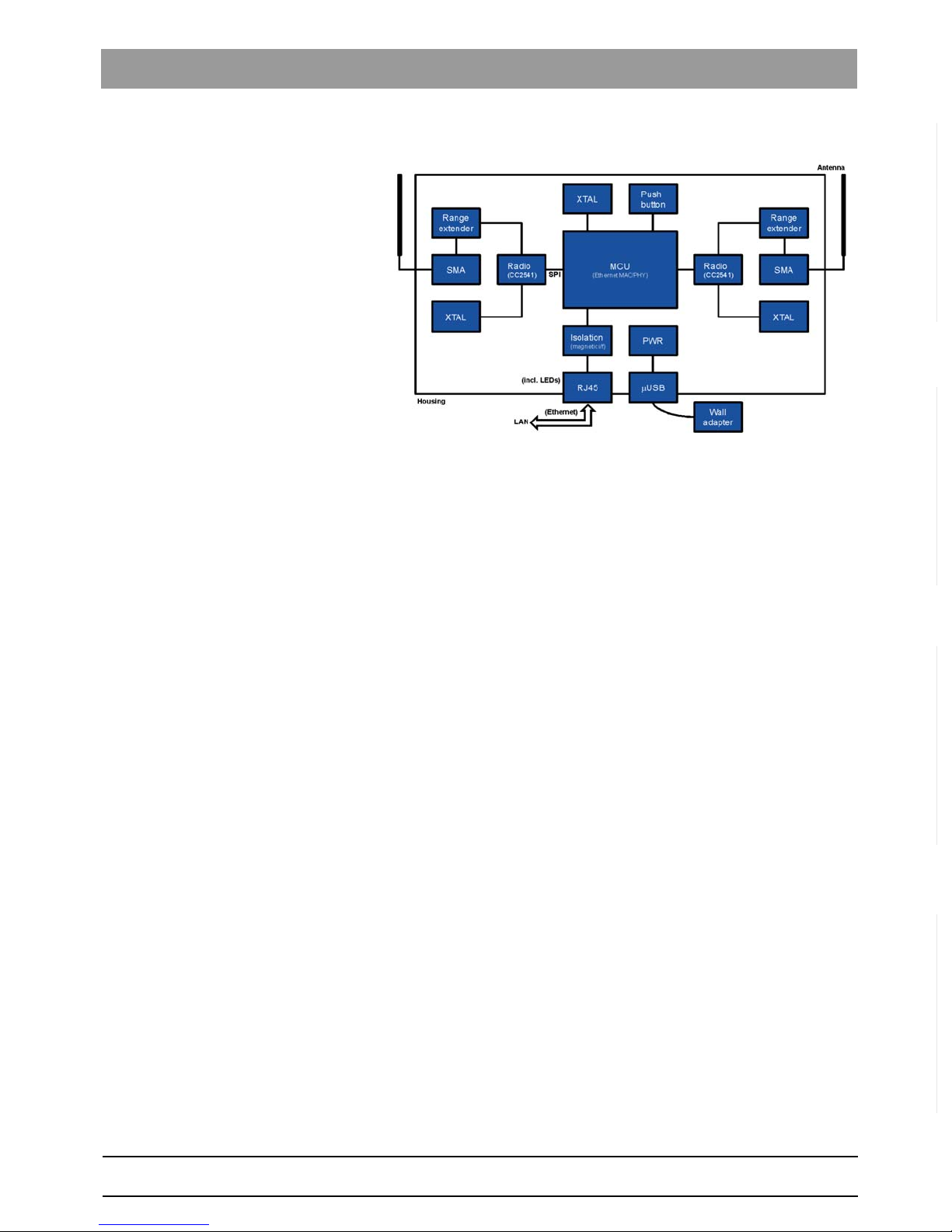
A schematic representation of a network unit is shown below.
As can be seen in the image, the network unit has four connection points:
●Antenna
The network unit has two antennas that are screwed on during
production. These antennas must not be removed or replaced with
different antennas.
●Micro-B USB
For power the network unit has a standard Micro-B USB port. A
standard 5V power adapter supplied in the package can be plugged
into this port. However, any standard USB 3.0 connection can be
used to power the network unit. The network unit integrated in the
CEREC mobile acquisition unit is powered through this port.
●RJ-45
The network unit has an RJ45 interface to which the standard
network cable (CAT5) can be connected. The network unit can be
connected to any other Ethernet communication device through this
interface. To establish a connection with the LAN infrastructure, you
can alternatively connect it to an Ethernet connection component
such as a hub or switch.

65 45 177 D3492
18 D3492.201.09.01.02 05.2015
6Networking Sirona Dental Systems GmbH
6.1CEREC Radio Device network overview Operating Instructions CEREC Radio Device
6Networking
This section describes the network function of the CEREC Radio Device.
Below you will find a list of the sections:
● CEREC Radio Device network overview
● Creating a network
● Network creation failures
● Extending the network
● Reset to factory defaults
● Network unit states
● Radio characteristics
6.1 CEREC Radio Device network overview
The network units in the CEREC Radio Device network create a so-called
peer-to-peer mesh network. This means that there is not a master or
slave as with Bluetooth, nor a central controlling access point for the
control as with WLANs.
As such there is no distinction between a network unit connected to a
milling unit, one that is built into an acquisition unit, or one that is
connected to LAN infrastructure: any network unit belonging to the same
network (see “Creating a network [ → 18]”) can communicate with all other
network units in this network that are in range. This is also applicable
when they are out of range of all other network units, making establishing
network connections very flexible.
The wireless network operates in the 2.4GHz band which is available
worldwide for license-free operation. It therefore needs to be able to
communicate with other wireless networks such as WLAN or Bluetooth
networks. The network accomplishes this by avoiding congested
channels wherever possible. However, the network is not completely
immune to interferences caused by other wireless technologies. The
result of these interferences can be a reduced range and drops in
performance. The network technology therefore offers several easy
mechanisms with which a network can be extended to achieve better
coverage (see “Extending the network [ → 20]”).
The network can also easily be extended and the coverage increased,
using LAN cables or even an existing LAN infrastructure (see “Increasing
the range [ → 30]”).
6.2 Creating a network
Network units that come out of the box have never been part of a network.
To allow for several networks of different owners to operate side-by-side
or in the same area, new network units must first create a network. This
is described in the following section.

65 45 177 D3492
D3492.201.09.01.02 05.2015 19
Sirona Dental Systems GmbH 6Networking
Operating Instructions CEREC Radio Device 6.3Network creation failures
båÖäáëÜ
6.2.1 Creation
To create a new network with a number of new network units the following
steps must be completed:
1. Bring all network units together in one room.
2. Power-up all network units within one minute.
3. Wait approximately one minute after the last network unit was
powered-up.
4. Check that all the network units are connected, indicated by the green
LED (see “LED displays [ → 11]”).
When completed, all network units will belong to a single network, which
can be operated as an independent network, and can communicate with
each other. The network created in this way is unique worldwide. See
“Network creation failures [ → 19]” should a problem arise.
6.2.2 Isolated network unit
A unique network is only created when two or more network units are
present. In case of an isolated network unit, no network is created until
another network unit is within range.
6.2.3 Permanent network
When a network unit has been added to a network, the network ID is
stored permanently. When network units are switched off and back on
again, they re-establish a connection with the network.
6.2.4 Installation
After the network has been set up, the network units can be switched off
and placed at their designated locations (to connect them to the milling
units, for example).
Since the network creation is permanent, the network units remain part of
the network even after switching off and switching back on again. This
applies even if they are placed outside of range of other network units, for
example in case of an isolated milling unit in a separate room.
6.2.5 Maximum size
A network can comprise up to three network units. Larger networks are
not possible.
6.3 Network creation failures
The following section describes potential issues which could arise when
creating a new network and offers solutions for each scenario.
6.3.1 Isolated network unit
When a single network unit is powered-up too late, it may not be part of
the network. This can be identified if the LED does not turn green.
This situation is the same as when a new network unit is added to an
existing network. This is described in “Extending the network [ → 20]”.

65 45 177 D3492
20 D3492.201.09.01.02 05.2015
6Networking Sirona Dental Systems GmbH
6.4Extending the network Operating Instructions CEREC Radio Device
6.3.2 Multiple networks created
When more than one network unit is powered-up too late, these network
units could form their own network.
Initially this will not be clear because all network units will indicate that
connections to other network units have been established with a green
LED (see “LED displays [ → 11]”).
One way of checking this is to connect a PC with a fixed IP address to
each network unit and try to ping the PCs from another PC. Another way
is to switch-off all but one network unit. Then complete the following steps
for each additional network unit:
1. Switch a network unit on.
2. Wait until the orange LED goes out.
3. The LED lights up green and the network unit belongs to the network.
4. Go to the next network unit.
If a network unit is not connected, the orange LED lights up constantly.
When this occurs the network unit must be reset to factory defaults (see
“Resetting to factory defaults [ → 22]”) and then added to the network by
switching one of the other network units off and back on again (see
“Extending the network [ → 20]”).
6.4 Extending the network
Additional new network units can be added to an existing network. This
section explains how this is done.
6.4.1 Adding a new network unit
New network units can be added to an existing network. However, to
prevent any network unit from becoming part of the network, the user
must complete four simple but specific steps:
1. Place the new network units next to a network unit belonging to the
network.
2. Switch-on the new network units.
3. Within one minute, switch the existing network unit off and then back
on again.
4. After one minute the new network units will become part of the
network.
Other manuals for Cerec
1
Table of contents


