P.7
2-2
骨位停止位置
050 ms
>2-3 後吸風延遲針數
2-5
前中吸風模式
關閉前中吸風
>2-6 中吸風間隔針數
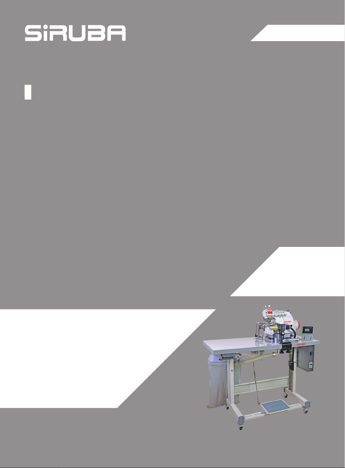
(二)、功能參數設置:
按 、 加減鍵,選中“功能參數設置”(圖 17),按下 右鍵,進入子功能表介面(圖 18):
2-1 送料速度(圖 18)
送料速度(預設 300 轉每分鐘)設置,通過 、 加減鍵,可調節送料速度或關閉。
圖19 圖20
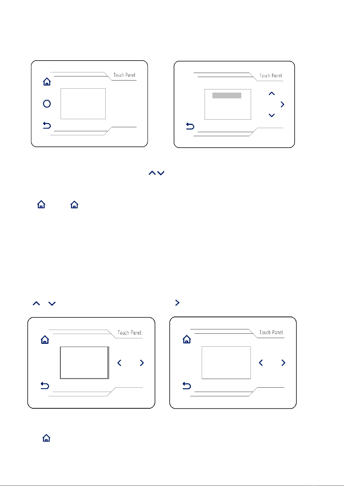
2-2 骨料停止位置(圖 19)
骨料停止位置(默認 50ms)設置,通過 、 加減鍵,可調節骨料停止位置。
2-3 後吸風延遲針數(圖 20)
後吸風延遲針數(默認 15 針)設置,通過 、 加減鍵,可調節針數以控制吸風開始時間。
圖21 圖22
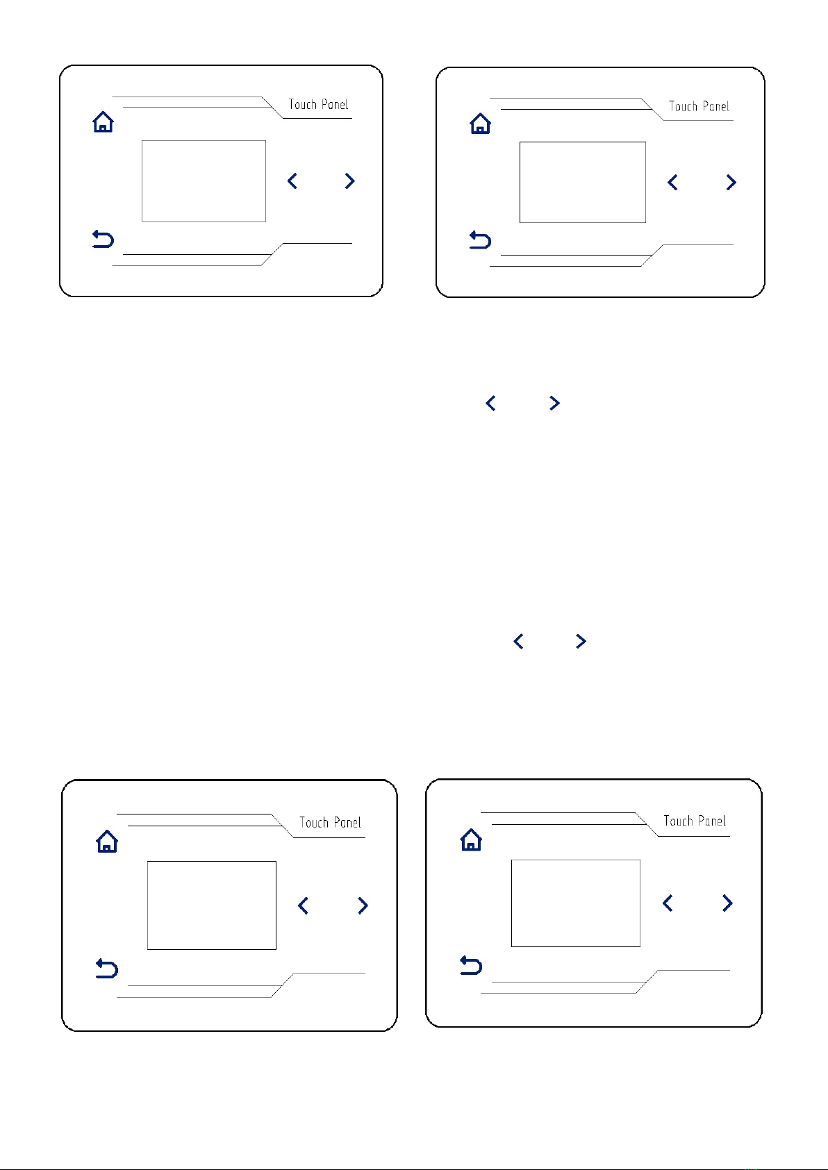
2-4 吸風保持時間(圖 21)
吸風保持時間(默認 1000ms)設置,通過 、 加減鍵,可調節吸風保持時間。
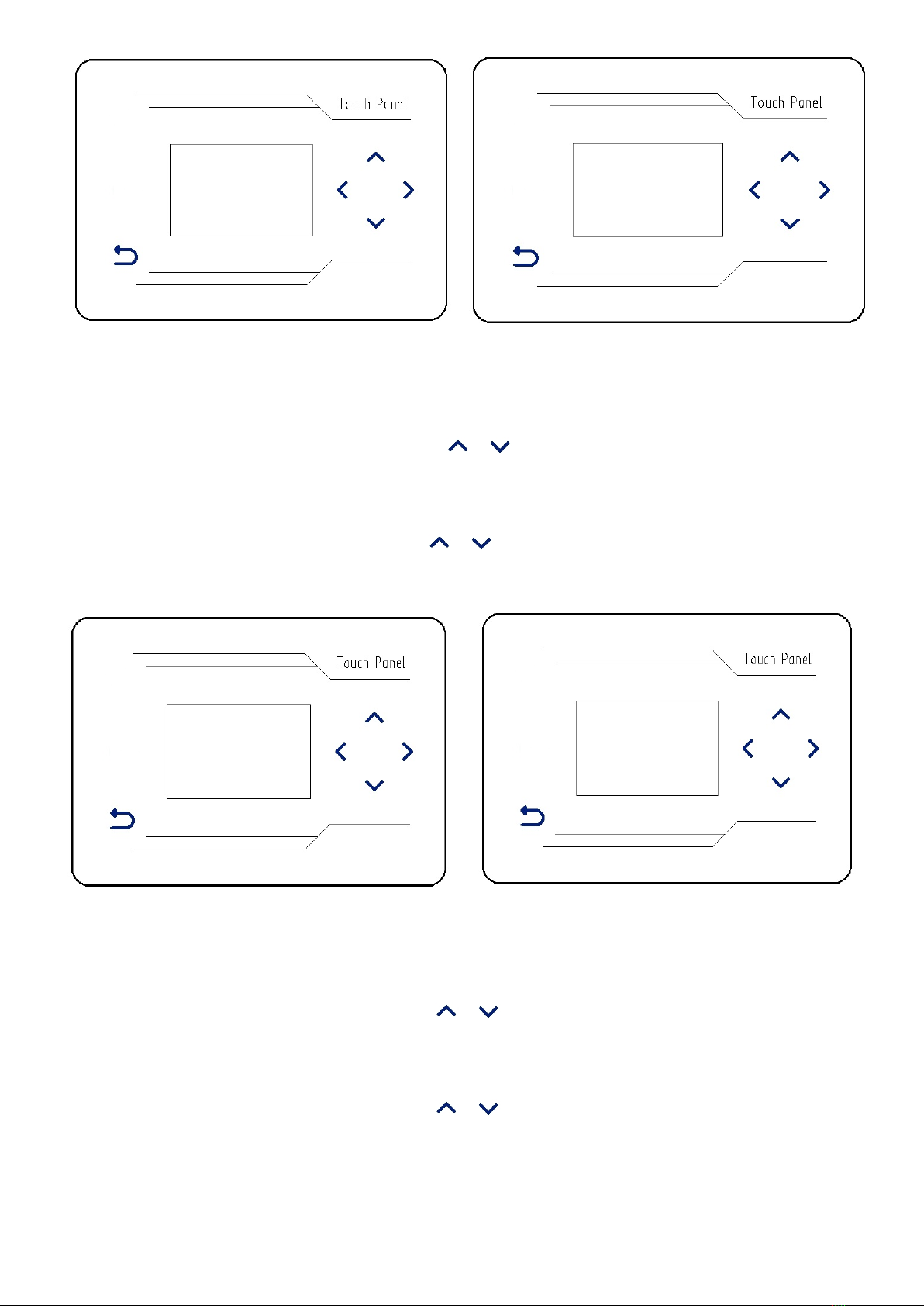
2-5 前中吸風模式(圖 22)
前中吸風模式(預設關閉前中吸風)設置,通過 、 加減鍵,可打開或者關閉前中吸風。
2-3
後吸風延遲針數
015
>2-4 吸風保持時間
2-4
吸風保持時間
0100/10ms
>2-5 前中吸風模式