Siruba LZ457A Datasheet

LZ457A
~m
~BJ3~~1tt=~
INSTRUCTION
AND
PARTS LIST
·
SinUaA
·
CE
®
tai**lmiSJ~~N1}6J
KAULIN
II
FG.
CO.,LTD.
From the library of: Superior Sewing Machine & Supply LLC

Contents
Application · · · · · · · · · · · · · · · · · · · · · · · · · · · · · · · · · · · · · · · · · · · · · · · · · · · •· · • · 2
Notes
on
safety · · · · · · · · · · · · · · · · · · · · · · · · • · · · · · · · · · · · · · · · · · · · · · · · · · · · · 2
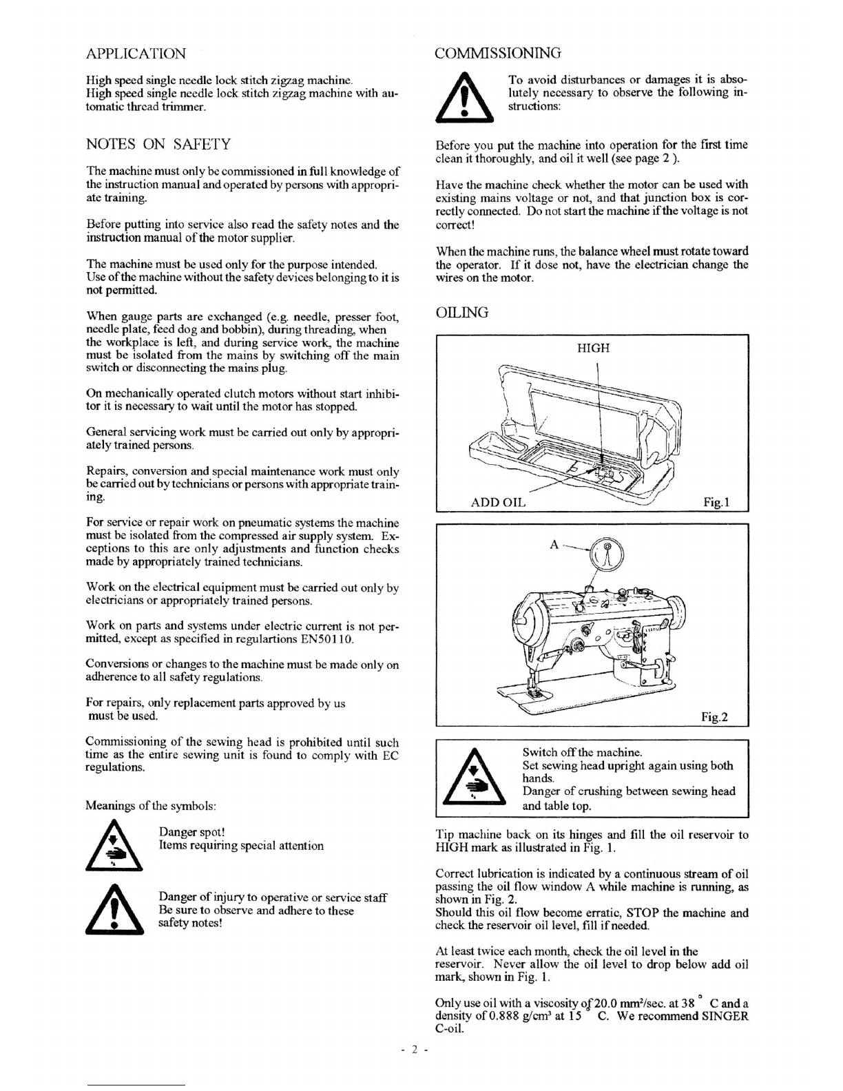
Commissioning · · · · · · · · · · · · · · · · · · · · · · · · · · · · · · · · · · · · · · · · · · · · · · · · · · · · 2
Oiling · · · · · · · · · · · · · · · · ·
~
· · · · · · · · · · · · · · · · · · · · · · · · · · · · · · · · · · · · · · · · · · · 2
Needle and thread · · · · · · · · · · · · · · · · · · · · · · · · · · · · · · · · · · · · · · · · · · · · · · · · · · · · 3
Inserting the needle · · · · · · · · · · · · · · · · · · · · · · · · · · · · · · · · · · · · · · · · · · · · · · · · · · 3
Winding
fue
bobbin · · · · · · · · · · · · · · · · · · · · · · · · · · · · · · · · · · · · · · · · · · · · · · · · · · 3
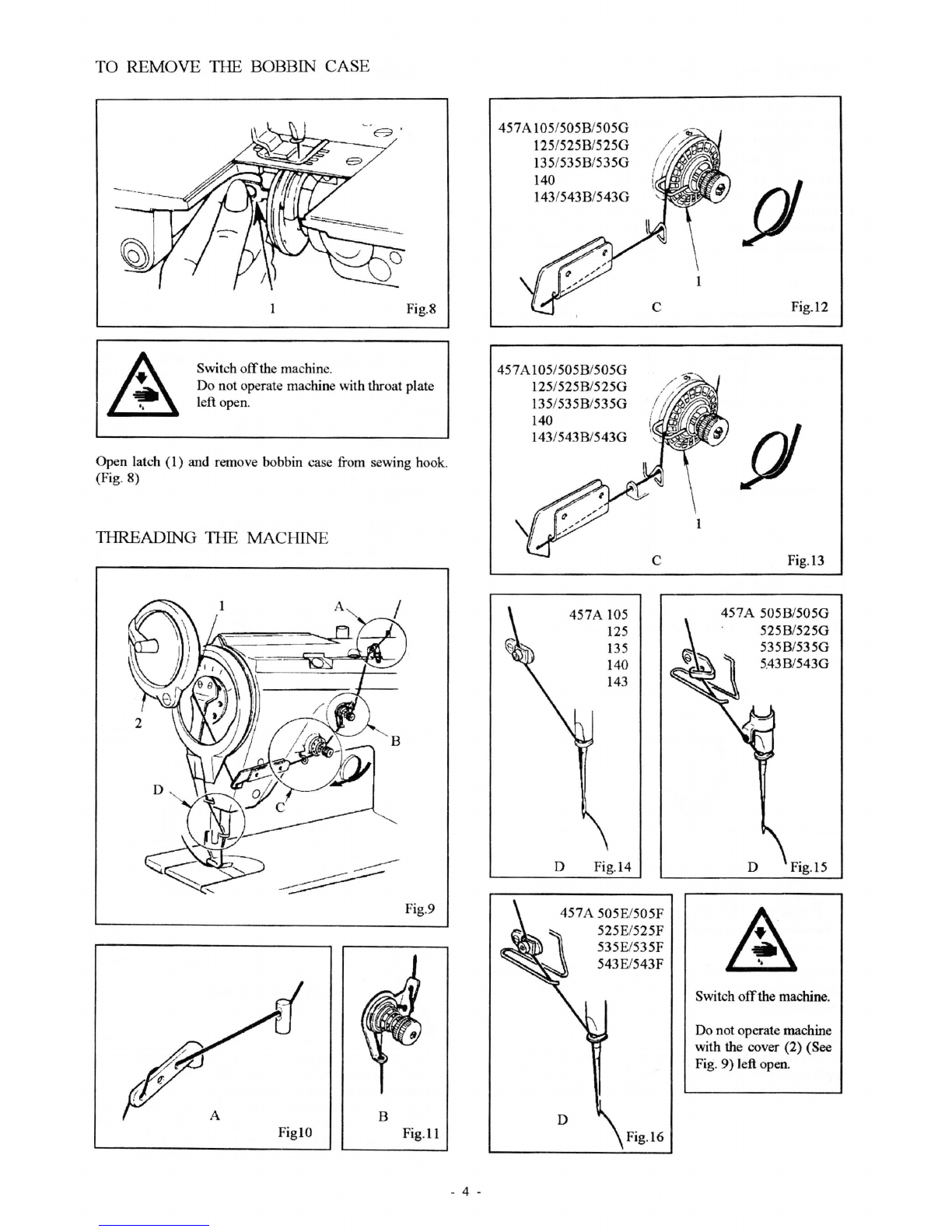
1breading the bobbin case · · · · · · · · · · · · · · · · · · · · · · · · · · · · · · · · · · · · · · · · · · · · · 3
To remove the bobbin case · · · · · · · · · · · · · · · · · · · · · · · · · · · · · · · · · · · · · · · · · · · · · 4
1breading
fue
machine · · · · · · · · · · · · · · · · · · · · · · · · · · · · · · · · · · · · · · · · · · · · · · · · 4
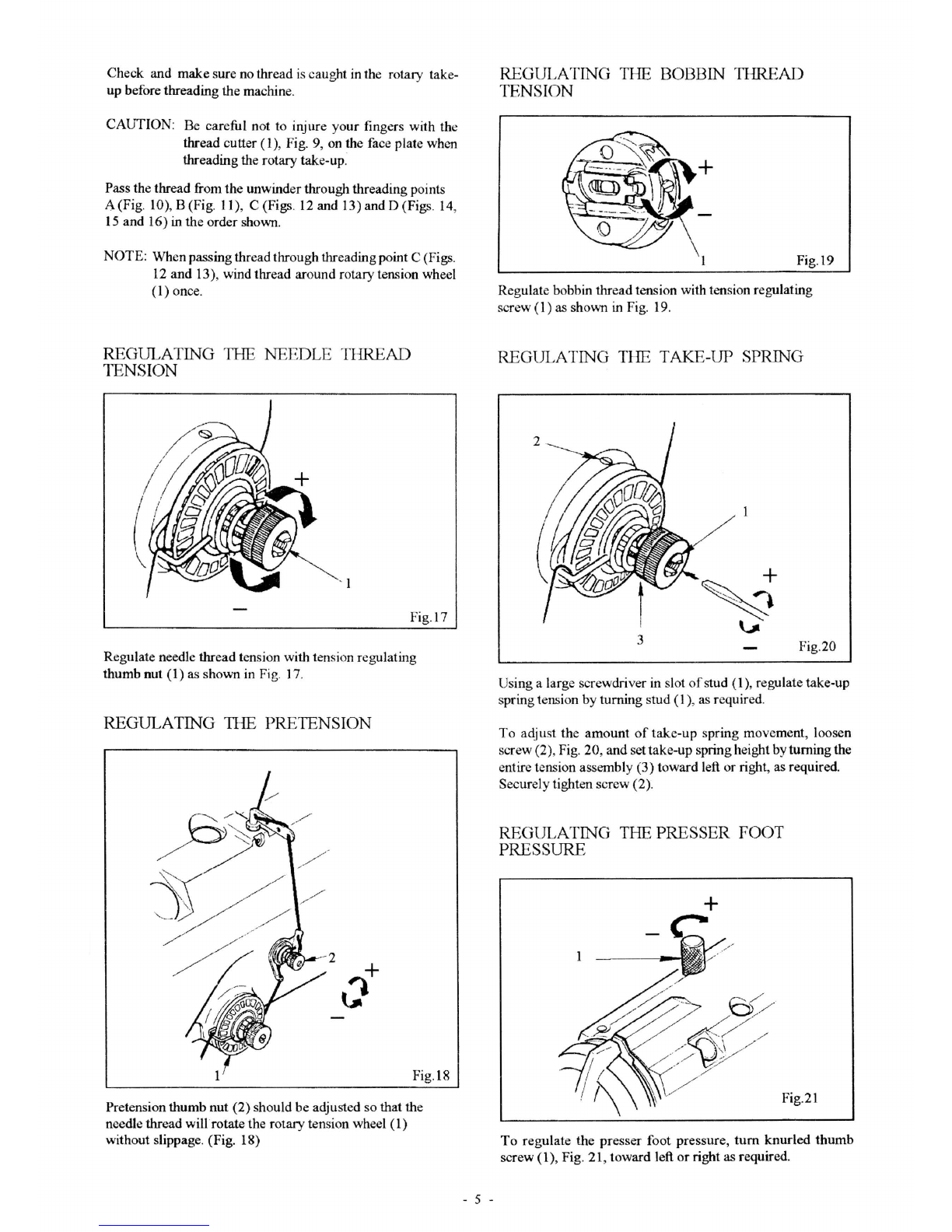
Regulating the needle thread tension · · · · · · · · · · · · · · · · · · · · · · · · · · · · · · · · · · · · · 5
Regulating the pretension · · · · · · · · · · · · · · · · · · · · · · · · · · · · · · · · · · · · · · · · · · · · · · 5
Regulating the bobbin thread tension · •· · · · · · • · • · • · · · · · · · · · · · · · · · • · · • · · • · • 5
Regulating the take-up spring • · · · · · · · · · · · · · · · · · · · · · · · · · · · · · · · · · · · · · · · · · · 5
Regulating the presser foot pressure · · · · · · · · · · · · · · · · · · · · · · · · · · · · · · · · · · · · · · 5
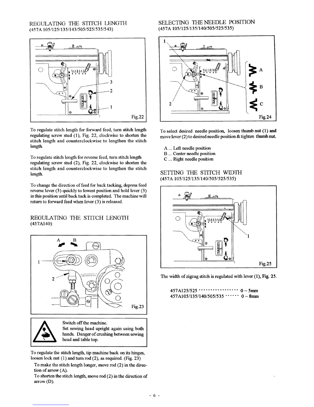
Regulating the stitch length · · · · · · · · · · · · · · · · · · · · · · · · · · · · · · · · · · · · · · · · · · · · 6
(457A105/125/135/143/505/525/535/543)
Regulating the stitchlength (457A140) · · · · · · · · · · · · · · · · · · · · · · · · · · · · · · · · • • · 6
Selecting the needle position · · · · · · · · · · · · · · · · · · · · · · · · · ·
··
· · · · · · · · · · · · · · · · 6
(457A105/125/135/140/505/525/535)
Setting the stitch width · · · · · · · · · · · · · · · · · · · · · · · · · · · · · · · · · · · · · · · · · · · · • • • · 6
(457A105/125/135/140/505/525/535)
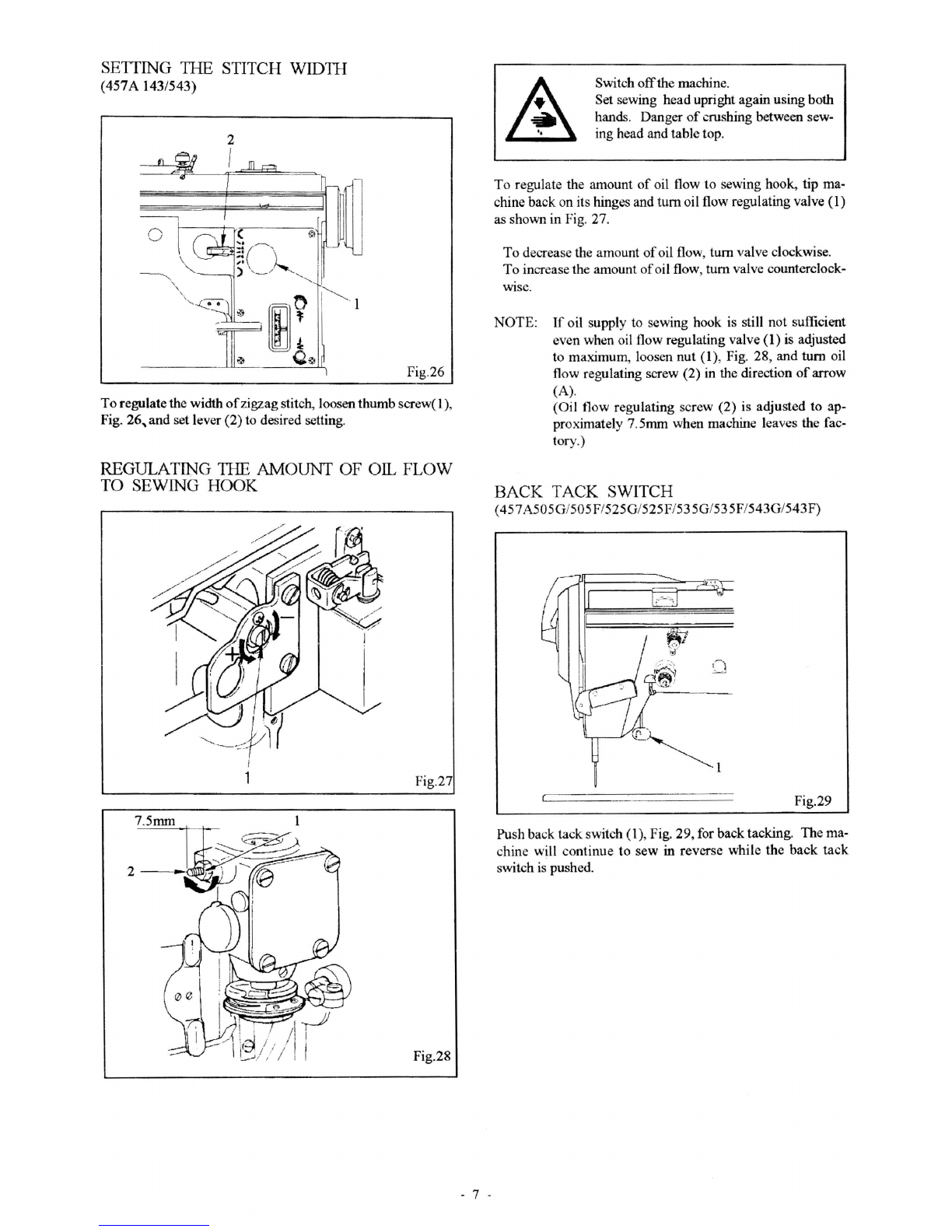
Setting the stitch width (457A 143/543) · · · · · · · · · · · · · · · · · · · · · · · · · · · · · · · · · · · 7
Regulating the amount
of
oil flow to sewing hook · · · · · · · · · · · · · · · · · · · · · · · · · · 7
Back tack switch · · · · · · · · ··· · · · · · · · · · · · · · · · · · · · · · · · · · · · · · · · · · · · · · · · · · · 7
(457A505G/505F/525G/525F/535G/535F/543G543F)
Adjusting
fue
slack needle thread regulator · · · · · · · · · · · · · · · · · · · · · · · · · · · · · · · · 8
(457A505E/505F/525E/525F/535E/535F/543E/543F)
Adjusting the bobbin thread holder · · · · · · · · · · · · •· · · · · · · · · · · · · · · · •· •· · · · · · 8
(457A505/525/535/543)
Adjusting
fue
length
of
thread end in needle eye · · · · · · · · · · · · · · · · · · · · · · · · · · · · · 8
(457A505/525/535/543)
Adjusting the needle tread holder puller · · · · · · · · · · · · · · · · · · · · · · · · · · · · · · · · · •• 8
(457A505E/505F/525E/525F/535E/535F/543E/543F)
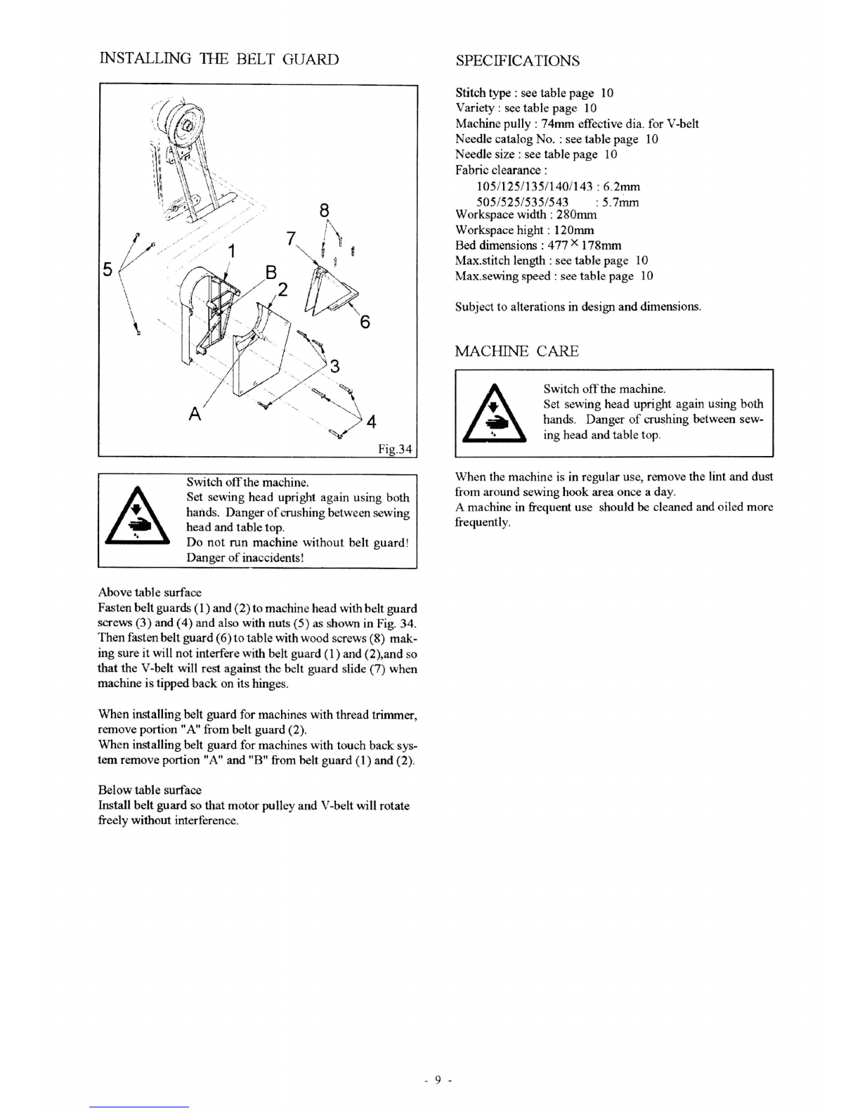
Installing ilie belt guard · · · · ··· · · · · · •· · · · · • • • · · · · • • · •· · • · · · · · · · · · · · · · • • • 9
Specifications · · · · · · · · · · · · · · · · · · · • · · · · · · · • · • • · • · • • • · • · · · · · · · · · · · · · · • 9
Machine care · · · · · · • · · · · · · •• · · · · · · · · · • · · · · · · • · · •· · · · · · · •· · · • • • · · · · · • 9
From the library of: Superior Sewing Machine & Supply LLC

APPLICATION
High speed single needle lock stitch zigzag machine.
High speed single needle lock stitch zigzag machine with au-
tomatic thread trimmer.
NOTES ON SAFETY
The machine must only be commissioned in full knowledge
of
the instruction manual andoperated bypersons with appropri-
ate training.
Before putting into service also read the safety notes and the
instruction manual
of
the motor supplier.
The machine
must
be used only for
the
purpose intended.
Use
ofthe
machine without
the
safetydevices belonging
to
it is
not permitted.
When
gauge parts are exchanged (e.g. needle, presser foot,
needle plate, feed
dog
and bobbin), duringthreading, when
the workplace is left, and during service work,
the
machine
must
be
isolated from the
mains
by
switching
off
the
main
switch or disconnecting the mains plug.
On
mechanically operated clutch motors without start inhibi-
tor
it is necessary
to
wait until
the
motor has stopped.
General servicing
work
must
be carried
out
only by appropri-
ately trained persons.
Repairs, conversion and special maintenance
work
must only
be carriedout
by
technicians
or
personswithappropriatetrain-
ing.
For service
or
repair work
on
pneumatic systems the machine
must
be isolated from the compressed
air
supply system. Ex-
ceptions
to
this
are
only
adjustments
and
function checks
made
by
appropriately trained technicians.
Work
on the electrical equipment
must
be carried
out
only by
electricians
or
appropriately trained persons.
Work
on parts
and
systems under electric current is not per-
mitted, except as specified in regulartions EN50110.
Conversions or changes
to
the machine
must
be
made
only on
adherence
to
all safety regulations.
For repairs, only replacement parts approved
by
us
must
be used.
Commissioning
of
the
sewing
head
is prohibited until such
time as the entire sewing
unit
is found to comply with EC
regulations.
Meanings
ofthe
symbols:
Danger
spot!
Items requiring special attention
Danger
of
injury
to
operative
or
service
staff
Be
sure
to observe and adhere to these
safety notes!
- 2 -
COMMISSIONING
To
avoid
disturbances
or
damages
it
is abso-
lutely necessary
to
observe
the
following in-
structions:
Before
you
put
the
machine into operation
for
the ftrst
time
clean itthoroughly, and oil it well (see page 2
).
Have
the machine check whether the motor
can
be used with
existing mains voltage
or
not,
and
that
junction
box
is cor-
rectly connected.
Do
not startthe machine
if
the
voltage is not
correct!
When
the machine runs, the balance wheel
must
rotate
toward
the operator.
If
it dose not, have the electrician change the
wires on the motor.
OILING
HIGH
Fig.I
Fig.2
Switch
offthe
machine.
Set sewing
head
upright
again
using both
hand'S.
Danger
of
crushing between sewing
head
and table top.
Tip
machine
back
on its hinges and fill the oil reservoir
to
HIGH
mark
as illustrated
in
Fig. 1.
Correct lubrication is indicated by a continuous stream
of
oil
passing the oil flow window A while machine is running, as
shown in Fig. 2.
Should this oil flow become erratic,
STOP
the machine and
check the reservoir oil level, fill
if
needed.
At least twice each month, check
the
oil level in the
reservoir.
Never
allow
the oil level
to
drop below
add
oil
mark,
shown in Fig.
1.
Only
use oil with a viscosity
o{20.0
mm
2/sec.
at
38
o C
and
a
density
of0.888
g/cm3 at 15 C.
We
recommend
SINGER
C-oil.
From the library of: Superior Sewing Machine & Supply LLC

NEEDLE AND 11-IREAD
Size of needle should be detennined in accordance with the
size
ofthread
used
and
type
of
material being sewn. A correct
sizeneedle will permit the thread
to
pass freely through the eye
of
th
e needle and avoid strain and breaking. A bent needle
will cause your machine to skip stitches. A hook
or
burr on
the needle point will result in a finish that looks blurred and
when short stitches are used some materials
may
be cut.
Theref
ore,
to
obtain best sewing results, use
SINGER
needles.
For
li
g
ht
-For medium-
Applica
ti
on of class weight
wei
g
ht
,
materials
mat
er
ials
Max.
t
hr
ead A Me
tri
c No. 120-
10
0
lOO
-
60
si
ze-
sy
ntheti
c Co
tton
No. 80-
60
60- 30
]I
S
(S
INGER
) #
8-
J:HO
#12-#16
N
ee
d
le
si
ze
Me
tri
c 60-
70
80- 100
1906
-·
01
(
13
5X53)
1906-07
Catalog No. .(
Needl
e system)
(1
35
'X
53
MBa
ll
)
87
52
-·
64
(1
35
X53 Lg E
cc
G L
Ba
ll
)
.Aor
an
equivalent
s
ize
of
ot
her type
of
thr
e
ad.
INSERTING
THE
NEEDLE
(See
Fig
.3)
Fig.3
Switch
off
the
machine.
Do
not
operate
without
finger
guard
(2)!
(See
Fig.
3)
Danger
of
injury!
Use cat. No. 1906-01
(135
X 53), 1906-07 (135 X 53 M
Ball),
8752-64
(135
X 135
Lg
G Ecc L Ball)'needles only.
(See table page.)
Set the needle
bar
at
its highest point. Loosen needle set
screw (1). (see Fig.
3)
Insert the needle in
the
needle
bar
and
push
it up as far as it will go.
Make
sure its long groove
faces toward the front. Tighten needle set screw (1) securely.
- 3 -
WINDING
11-IE
BOBBIN (See Fig.4)
Fig.4
Bobbin winder spindle (1) rotates in
the
direction
of
arrow
(A).
Push lever (2) inthe direction
of
aiTow
(B)
to windthe bobbin.
To
adjust amount
of
thread
on
bobbin, loosen set screw
(3)
in
lever (2) and move lever (2),
as
required. Securelytighten set
sc
rew
(3).
Adjust the thumb nut (
4)
to regulate the tension for bobbin
winding.
If
thread
winds unevenly on bobbin, loosen screw (5)
and
move
bobbin winder pretension (6)
up
or down,
as
required,
and tighten screw (5).
THREADING
11-IE
BOBBIN CASE
AB
2
Fig.6
Switch
off
the machine.
Fig.5
A
B
Fig.?
Hold
bobbin so
that
thread
will unwind
in
the direction shown
in
Fig
. 5 and place the bobbin into bobbin case.
Pull the thread into slot (1) and under
the
tension spring
(2)
and into slot
(3)
as
shown in Fig. 6.
Then
draw
thread
into
delivery eye
(A
or
B), as shownin Fig. 6. Use delivery eye (A)
for sewing light weight material, as shown in Fig. 7.
Use delivery eye
(B)
for sewing
medium
weight material.
From the library of: Superior Sewing Machine & Supply LLC

TO REMOVE
Tiffi
BOBBIN CASE
Fig.8
Switch
off
the machine.
Do not operate machine with throat plate
left open.
Open latch (
1)
and remove bobbin case from sewing hook.
(Fig. 8)
THREADING
1HE
MACI-IINE
Fig.9
B
FiglO Fig.l1
- 4 -
457
A105/505B/505G
125/525B/525G
135/535B/535G
140
143/543B/543G
457
A105/505B/505G
125/525B/525G
13
5/
53
5B/535G
140
143/543B/543G
D
457A
105
125
135
140
143
Fig.14
c
c
457A
505E/505F
D
525E/525F
535E/535F
543E/543F
Fig.16
Fig.l2
Fig.13
457A 505B/505G
525B/525G
535B/535G
5.43B/543G
Fig.l5
Switch
off
the machine.
Do not operate machine
with the cover (2) (See
Fig. 9) left open.
From the library of: Superior Sewing Machine & Supply LLC

Check and
make
sure no thread
is
caught in the rotary take-
up before threading the machine.
CAUTION: Be careful not to injure
your
fingers with the
thread cutter (1), Fig. 9, on the face plate when
threading the rotary take-up.
Pass the thread from
the
unwinder through threading points
A(Fig.
10), B (Fig. 11), C (Figs. 12 and 13) and D (Figs. 14,
15
and
16) in the order
sho\\-11.
NOTE:
Whenpassing threadthrough threading point C (Figs.
12
and
13), wind thread around rotary
ten.<.;
ion wheel
(I)
once.
REGULATING
THE
NEEDLE 11-IREAD
TENSION
Fig.l7
Regulate needle thread tension with tension regulating
thumb nut (1) as shown in Fig. 17.
REGULATING
1HE
PRETENSION
Fig.18
Pretension thumb
nut
(2)
should be adjusted so that the
needle thread will.rotate the rotary tension wheel (1)
without slippage. (Fig. 18)
- 5 -
REGULATING THE BOBBIN THREAD
TENSION
Fig.l9
Regulate bobbin thread tension with tension regulating
screw (1)
as
sho\\-11
in Fig. 19.
REGULATING THE TAKE-UP SPRING
3 Fig.20
Using a large screwdriver in slot
of
stud (1
),
regulate take-up
spring tension
by
turning
stud
(1), as required.
To
adjust
the
amount
of
take-up
spring movement, loosen
screw (2), Fig. 20, and
settake-up
springheight byturning the
entire tension assembly (3) toward left
or
right, as required.
Securely tighten screw (2).
REGULATING THE PRESSER FOOT
PRESSURE
Fig.21
To
regulate
the
presser foot pressure,
tum
knurled
thumb
screw (1), Fig. 21, toward left
or
right as required.
From the library of: Superior Sewing Machine & Supply LLC

REGULATING THE STITCH
LENGTI-I
(457A 105/125/135/143/505/525/535/543)
Fig.22
To regulate stitch length for forward feed, turn stitch length
regulating screw stud (1), Fig. 22, clockwise to shorten the
stitch length and counterclockwise
to
lengthen the stitch
length.
To regulate stitch length for reverse feed, turn stitch length
regulating screw stud (2), Fig. 22, clockwise to shorten the
stitch length
and
counterclockwise
to
lengthen the stitch
length.
To change the direction
of
feed for back tacking, depress feed
reverse lever (3) quickly to lowest position and hold lever (3)
inthis position until backtackis completed. The machinewill
return to forward feed when lever (3)
is
released.
REGULATING
Tiffi
STITCH LENGTII
(457A140)
1 .
A B
Jill'
~
Fig.23
Switch
off
the machine.
Set sewing head upright again using both
hands. Danger
of
crushing between sewing
head and table top.
To regulate the stitch length, tip machine back on its hinges,
loosen lock nut (1) and turn rod (2), as required. (Fig. 23)
To
make the stitch length longer, move rod (2) in the direc-
tion
of
arrow (A).
To shortenthe stitch length, move rod (2) inthe direction
of
arrow (D).
SELECTING TIIE NEEDLE POSITION
(457A 105/125/135/140/505/525/535)
- 6 -
Fig.24
To select desired needle position, loosen thumb nut (1) and
move lever (2)to desired needle position& tighten thumbnut.
A ... Left needle position
B
..
. Center needle position
C ... Right needle position
SETTING THE STITCH WIDTII
(457A 105/125/135/140/505/525/535)
Fig.25
The width
of
zigzag stitch is regulated with lever
(1)~
Fig. 25.
457Al25/525 •••••••••••• ••• ••
0-
5mm
457
Al05/135/140/505/535 ••••••
0-
8mm
From the library of: Superior Sewing Machine & Supply LLC

SETTING
11-IE
STITCH WIDTII
(457A
143/543)
Fig.26
To
regulate the width
of
zigzag stitch, loosen thumb screw(1),
Fig.
26,
and set lever (2) to desired setting.
REGULATING
TilE
AMC)UNT OF OIL FLOW
TO SEWING HOOK
Fig.27
Fig.28
- 7 -
Switch
off
the machine.
Set sewing head upright again using both
hands. Danger
of
crushing between sew-
ing head and table top.
To
regulate the amount
of
oil flow
to
sewing hook, tip ma-
chine back on its hinges and
tum
oil flow regulating valve (1)
as shown in Fig. 27.
To decrease the amount
of
oil flow,
tum
valve clockwise.
To increase the amount
of
oil flow,
tum
valve counterclock-
Wise.
NOTE:
If
oil supply to sewing hook
is
still not sufficient
even when oil flow regulating valve (1)
is
adjusted
to maximum, loosen
nut
(1), Fig. 28, and
tum
oil
flow regulating screw (2) in the direction
of
arrow
(A).
(Oil flow regulating screw (2) is adjusted to ap-
proximately
7.
5nun when machine leaves the fac-
tory.)
BACK TACK SWITCH
(
457
A505G/505F/525G/525F/
53
50
/535F/543G/543F)
(
-==
============
Fig.29
Push back tack switch (1), Fig. 29, for backtacking. The ma-
chine will continue to sew in reverse while the
back
tack
switch
is
pushed.
From the library of: Superior Sewing Machine & Supply LLC

ADJUSTING THE SLACK NEEDLE THREAD
REGULATOR
(457A 505E/505F/525E/525F/535E/535F/543E/543F)
2
Fig.30
Switch
off
the machine.
To adjust the slackness
ofthe
needle thread, loosen wing bolt
(
1)
and slide it up or down, as required, usingthe indicator (2)
and graduation as a yardstick as shown in Fig. 30.
Move wing bolt upward
in
the direction
of
arrow (A) to in-
crease slackness.
Move wing bolt downward
in
the direction
of
arrow (B) to
decrease slackness.
NOTE: Excessive slackness
ofthe
needle thread may cause
birds nest and thread breakage at start
of
sewing.
Insufficient slackness may result in needle thread
being pulled out
of
needle eye, skip stitching and
needle breakage at start
of
sewing.
When slack needle thread regulator function
is
not
required, turn offswitch (3) shown in Fig. 30.
AD.nJSTING
TilE
BOBBIN THREAD
HOLDER
(
457
A 505/525/535/543)
Switch offthe machine.
Fig.
31
Set sewing head upright again using both
hands. Danger
of
crushing between sewing
head and table top.
To adjust the length ofthread end remaining onthe underside
of
the material at start
of
sewing, tip machine
back
on its
hinges and turn adjusting screw (1) as shown in Fig. 31.
- 8 -
To increase the length
of
thread end, turn adjustingscrew (1)
clockwise.
To decrease the length
of
thread end, turn adjusting screw
(
1)
counterclockwise.
ADJlJSTING THE LENGTII OF TIIR.EAD
END
IN
NEEDLE
EYE
(
457
A 505/525/535/543)
...
...
A B
Fig.32
Switch
off
the
machine.
To adjustthe length
of
threadend remaining in the needle eye,
loosen screw (1), Fig. 32, and move face plate thread puller
(2), as required.
To shortenthe thread end, move thread puller inthe direction
of
arrow (A).
To lengthen the thread end, move thread puller in the direc-
tion
of
arrow (B).
ADnJSTING
TilE
NEEDLE TIIREAD HOLDER
PULLER
(457A 505E/505F
/5
25E/525F/535E/53 5F/543E/543F)
1 &
2
Switch
off
the
machine.
Fig.33
To adjust the holding strength
of
needle thread holder puller,
loosen screws (1) and (2), Fig. 33, and adjust the pressure
of
the needle thread holder puller springs (3) and (4) againSt
needle thread holder puller.
From the library of: Superior Sewing Machine & Supply LLC

INSTALLING
11-IE
BELT GUARD
I/
..
/
s
(/
/ .
\
\
1
Fig.
34
Switch
off
the machine.
Set sewing head upright again using both
hands. Danger
of
crushing between sewing
head and table top.
Do not run machine without belt guard!
Danger
of
inaccidents!
Above table surface
Fasten beltguards (1) and (2)to machine head with belt guard
screws (3) and (4) and also with nuts (5) as shown in Fig. 34.
Then fasten belt guard (6)
to
table with wood screws (8) mak-
ing sure it will not interfere with belt guard (1) and (2),and so
that the V-belt will rest against the belt guard slide (7) when
machine is tipped back on its hinges.
When installing belt guard for machines with thread trimmer,
remove portion "A" from belt guard (2).
When installing belt guard for machines with touch back sys-
tem remove portion "A" and "B" from belt guard (1) and (2).
Below table surface
Install belt guard so that motor pulley and V-belt will rotate
freely without interference.
- 9 -
SPECIFICATIONS
Stitch type : see table page
10
Variety: see table page
10
Machine
pully:
74mm effective dia. for V-belt
Needle catalog No.
:see
table page
10
Needle size : see table page
10
Fabric clearance:
105/125/135/140/
143:
6.2mm
505/525/535/543 :
5.
7mm
Workspace width: 280mm
Workspace hight: 120mm
Bed dimensions : 477 X 178mm
Max.stitch length : see table page
10
Max.sewing speed: see table page
10
Subject to alterations
in
design and dimensions.
MACHINE CARE
Switch offthe machine.
Set sewing head upright again using both
hands. Danger
of
crushing between sew-
ing head and table top.
When the machine
is
in regular use, remove the lint and dust
from around sewing hook area once a day.
A machine
in
frequent use should be cleaned and oiled more
frequently.
From the library of: Superior Sewing Machine & Supply LLC

Max.
sewing speed
Max.
sewing speed
Max.·
needle
bight
Max.
stitch
length
Needle
catalog
No.
Variety
Stitch
type
in
s.p.11
.&
(Needle system)
1.
3
mm
1906-07
105L
20
SPI
(135
X
53
M
Ball)
8.0
mm
WN
5.
1
mm
1906-01
105M
5 SPI
(135
X
53)
2.0
mm
1906-07
125L
304(zigzag
lockstitch)
13
SPI
(135
X
53
M
Ball)
5,000
5.0
mm
4.
2
mm
1906-01
125M
6 SPI
(135
X
53)
1.
3
mm
1906-07
135L
\1\1\
20
SPI
(135
X
53
M
Ball)
2.5
mm
1906-01
135M
321(3
step
zigzag)
10
SPI
(135
X
53)
~
6.5
mm
8752-64
140M
4,500 I I
(135
X
53
Lg
G
Y«
fagot
stitc
h
Ecc
L
Ball)
8.0
mm
1.
3
IIIII
1906-07
143L
~
20
SPI
(135
X
53
M
Ball)
4,200
2.5
llllll 1906-01
143M
scalop
stitch
10
SPI
(135
X
53)
1.
3
mm
1906-07
505L
20
SPI
(135
X
53
M
Ball)
ww
5.
1
mm
1906-01
505M
5 SPI
(135
X
53)
2.0
mm
1906-07
525L
304(zigzag
lockstitch)
13
SPI
(135
X
53
M
Ball)
5,000
5.0
mm
4.2
mm
1906-01
525M
6 SPI
(135
X
53)
1.
3
mm
1906-07
535L
\1\1\
20
SPI
(135
X
53
M
Ball)
2.5
IDlB
1906-01
535M
321(3
step
zigzag)
10
SPI
(135
X
53)
8.0
mm
1.
3
IDlJ
1906-07
543L
~
10
SPI
(135
X
53
M
Ball)
4,200
2.5
mm
1906-01
54
3M
scalop
stitch
10
SPI
(135
X
53)
£ Depending
on
material
and
operation.
-
10-
From the library of: Superior Sewing Machine & Supply LLC

CONTENTS
Fl.
ROTARY
TAKE-UP
GUARD,
FACE
PLATE
--------------------------------------1
Fl.
ARM
SHAFT
,ROTARY
TAKE-UP
-------------------------------------------1
F2.
TENSION
RELEASER
,KNEE
LIFTER
ROCK
FRAME
2
F2.
PRESSER
BAR
,
THROAT
PLATE
,
FEED
DOG
-------------------------------2
F3.
NEEDLE
BAR
YOKE
,NEEDLE
------------------------------------3
F3
.
NEEDLE
BAR
CONNECTING
LINK
(FOR
105I125) 3
F4.
NEEDLE
BAR
CONN~CTING
LINK
(FOR
135/140)
F4.
NEEDLE
BAR
CONNECTING
LINK
(FOR
143) 4
4
F5.
NEEDLE
VIBRATING
YOKE
CONNECTING
LINK
CARRIER
FRAME
(FOR
105/125/135/140)--5
FS.
NEEDLE
VIBRATINGYOKECONNECTING
LINK
CARRIER
FRAME
(FOR
143)
-----------5
F6
.
FEED
REGURAT
I
NG
INDICATOR
,
LINK
--------------------------------------6
F6.
NEEDLE
VIBRATING
ADJUSTING
BRACKET--------------------------------------6
F7.
ARM
COVER
(TOP)
(ASSEMBLY)
---------------------------------------------7
F7.
PRETENSION
,TENSION
----------------------------------------------------7
F8.
HOOK
,
BOBBIN
CASE
----------------------------------------------------8
F8
.
HOOK
SHAFT
,
BEVEL
GEAR
-----------------
·
---------------------------------8
F9.
FEED
DRIVING
CONNECTION
,CARRIER
FRAME
----------------------------------9
F9
.
FEED
CONTROL
CAM
---------------------------------------------------------9
FlO.
FEED
DRIVING
ROCK
SHAFT
CRANK
---------------------------------------10
FlO.
BED
SHAFT
----------------------------------------------------------10
Fll.
ARM
COVER
(BACK)
11
Fll.
OIL
PUMP
BODY
----------------------------------------------------11
F12. 0
IL
RESERVOIR
AND
KNEE
LliTER
---------------------------------12
F12.
ACCESSORIES
Fl3.
BELT
GUARD
,
THREAD
UNWINDER
(2-SPOOL)
12
13
From the library of: Superior Sewing Machine & Supply LLC

ROTARY TAKE-UP GUARD, FACE PLATE
ARM SHAFT, ROTARY TAKE-UP
25 22
68-1
59-2
69-1
32
F1
From the library of: Superior Sewing Machine & Supply LLC

REF. NO.部件編號 DESCRIPTION 說明
F1-01
F1-02P
F1-03
F1-04
F1-05P
F1-06
F1-07
F1-08
F1-09P
F1-10
F1-11
F1-12
F1-13
F1-14
F1-15P
F1-16P
F1-17P
F1-18
F1-19W
F1-20
F1-21P
F1-22P
F1-23
F1-24
F1-25
F1-32P
F1-33
F1-34P
F1-35
F1-36P
F1-37
F1-38
F1-39
F1-40P
F1-41
F1-43
F1-44
F1-45
F1-46P
F1-47-2
F1-47-4
F1-48P
F1-49
F1-54
F1-55
F1-56P
F1-57
F1-58
F1-59
F1-59-1
F1-59-2
F1-60
F1-61
F1-62P
F1-63
F1-64
F1-66
F1-67
F1-68P
F1-68-1P
F1-69
F1-69-1
F1-70
ROTARY TAKE-UP GUARD (CPL.) 活動護蓋組
THREAD CUTTER CREW 螺釘
THREAD CUTTER 割線刀
ROTARY TAKE-UP GUARD (A) 活動蓋(A)
ROTART TAKE-UP SCREW 螺釘
ROTART TAKE-UP GUARD SPRING CATCH 彈片勾
WASHER 墊片
ROTARY TAKE-UP GUARD COVER (B) 活動蓋(B)
ROTARU TAKE-UP SCREW 螺栓
ROTARY TAKE-UP GUARD HINGE WASHER 墊圈
ROTART TAKE-UP GUARD HINGE SPRING WASHER C型墊圈
ROTARY TAKE-UP GUARD COVER WINDOW 護鏡
TOTARY TAKE-UP WASHER 墊圈
TOTARY TAKE-UP SCREW 螺釘
TOTARY TAKE-UP GUARD SCREW (LONG) 螺釘
TOTARY TAKE-UP GUARD SCREW (SHORT) 螺釘
FACE PLATE (CPL.) 前蓋板組
THREAD CUTTER SCREW NUT 螺母
THREAD CUTTER (ON FACE PLATE) 割線刀
THREAD CUTTER SCREW 螺釘
THERAD CUTTER SCREW 螺釘
FACE PLATE GASKET 前蓋板
FACE PLATE GASKET 防油墊片
TAKE-UP THREAD GUIDE 挑線導片
FACE PLATE SCREW 螺釘
MACHINE PULLEY 皮帶輪
MACHINE PULLEY SCREW 螺釘
BEARING FIXED STAND 軸承固定座
ARM SHAFT THRUST CALLAR SET SCREW 螺釘
ARM SHAFT BEARING 軸承(後)
ARM SHAFT CONNECTION BELT PULLEY(CPL.) 同步皮帶輪組
ARM SHAFT CONNECTION BELT PULLEY RING O型扣環
ARM SHAFT CONNECTION BELT PULLEY SET SCREW 螺釘
ARM SHAFT CONNECTION BELT PULLEY 同步皮帶輪
ARM SHAFT CONNECTION BELT 同步皮帶
ARM SHAET OIL SHIELD 橡膠油封
BOBBIN WINDER DRIVING WHEEL 摩擦齒輪
BOBBIN WINDER DRIVING WHEEL SET SCREW 螺釘
NEEDLE VIBRATING PINION (2) 蝸桿(2)
NEEDLE VIBRATING PINION (4) 蝸桿(4)
NEEDLE VIBRATING PINION SET SCREW 螺釘
ARM SHAFT BUSHING (CENTER) 上軸套襯(中)
ARM SHAFT BALLBEARING 軸承(前)
ARM SHAFT NEEDLE BAR CRANK 平衡塊
NEEDLE BAR CRANK STUD POSITION SCREW 螺釘
NEEDLE BAR CRANK THRUST WASHER 定向墊片
NEEDLE BAR CONNECTING CONNECTING LINK (CPL.) 針柱驅動組
NEEDLE BAR CONNECTING LINK 針柱驅動連桿
NEEDLE BAR CONNECTING LINK BEARING 套筒
NEEDLE DRIVING LEVER BEARING 針驅動桿軸承
NEEDLE BAR CONNECTING STUD 針柱夾
NEEDLE BAR OIL FELT CORD 油蕊
NEEDLE BAR CONNECTING STUD SCREW 螺釘
ROTARY TAKE-UP MOUNTUING DISK 天秤定向片
ROTARY TAKE-UP天秤
ENNDLE BAR CONNECTING LINK CLAMPING PLATE 固定片
NEEDLE BAR CONNECTING LINK GUID BLOCK 導軌
NEEDLE BAR CONNECTING LINK GUID BLOCK SCREW 螺釘
SCREW 螺釘
NEEDLE BAR CONNECTING CRANK STUD 傳動曲軸
PIN 栓
ARM SHAFT, ROTARY TAKE-UP 上主軸
1
1
1
1
1
1
1
1
2
1
1
1
1
1
1
1
1
1
2
2
1
1
1
12
1
2
1
2
1
1
2
1
1
1
1
2
1
1
6
1
1
1
4
1
1
1
1
1
1
1
1
1
1
1
2
2
1
1
1
QTY. 需求量
From the library of: Superior Sewing Machine & Supply LLC

10-1
1 -20
49-2
49 4- 46
TENSION RELEASER,KNEE LIFTER ROCK FRAME
PRESSER BAR,THROAT PLATE, FEED DOG
F2
From the library of: Superior Sewing Machine & Supply LLC

REF. NO.部件編號
F2-01
F2-02W
F2-03P
F2-04
F2-05
F2-06P
F2-07P
F2-08P
F2-09
F2-10
F2-10-1P
F2-10-2W
F2-11
F2-12
F2-13
F2-14
F2-15
F2-16
F2-17P
F2-20
F2-21
F2-22P
F2-23
F2-24
F2-25
F2-26
F2-27
F2-28P
F2-29
F2-30
F2-31
F2-32
F2-33P
F2-34
F2-35
F2-36
F2-37P
F2-38
F2-39
F2-44
F2-45P
F2-46P
F2-47
F2-49-2
F2-49-4
F2-50
F2-51
F2-52P
F2-53P
F2-54-2
F2-54-4
1
1
1
1
1
1
2
1
1
1
1
1
1
2
1
1
1
1
1
1
1
1
1
1
1
1
1
1
1
1
1
1
1
1
1
1
1
1
4
1
1
1
1
1
2
2
1
1
TENSION RELEASER (CPL.) 鬆緊釋放組
TENSION RELEASER ADJUSTING SCREW NUT 螺母
TENSION RELEASER ADJUSTING SCREW 螺釘
TENSION RELEASER 釋放柄
TENSION RELEASER SPRING 彈簧
TENSION RELEASER SCREW 螺釘
KNEE LIFTER ROCK FRAME HINGE SCREW 螺釘
KNEE LIFTER ROCK FRAME HINGE LOCK SCREW 螺釘
KNEE LIFTER ROCK FRAME (CPL.) 膝提搖桿組
KNEE LIFTER ROCK FRAME HINGE 搖桿固定架
SCREW 螺釘
NUT 螺母
KNEE LIFTER ROCK FRAME HINGE STUD PIN 插栓
KNEE LIFTER ROCK FRAME 膝提搖桿
KNEE LIFTER LIFTING ROD (ASS'Y) 搖桿驅動柄
KNEE LIFTER LIFTING ROD RING E型扣環
KNEE LIFTER LIFTING ROD SPRING 釋放彈簧
KNEE LIFTER LIFTING ROD SPRING COLLAR 固定圈
KNEE LIFTER LIFTING ROD SPRING SCREW 螺釘
PRESSER BAR SPRING ADJUSTING SCREW 活動栓
PRESSER BAR SPRING ADJUSTING SCREW FRICTION 彈力夾
PRESSER BAR SPRING SCREW 螺釘
PRESSER BAR SPRING (CPL.) 壓力板組
PRESSER BAR SPRING 壓力彈簧板
PRESSER BAR SPRING TUBE 橡膠套圈
PRESSER BAR SPRING WICK 油蕊
PRESSER BAR LIFTER (CPL.) 手提柄
PRESSER BAR LIFTER SET SCREW 螺釘
PRESSER BAR LIFTTING CAM STUD O-RING 橡膠油封
PRESSER BAR LIFTTING CAM STUD (CPL.) 手轉軸
PRESSER BAR BALL 鋼珠
PRESSER BAR POSITION GUIDE 手提導位柄
PRESSER BAR POSITION GUIDE SCREW 螺釘
PRESSER BAR BUSHING COVER 塑膠護套
PRESSER BAR BUSHING 壓腳柱軸套筒
PRESSER BAR 壓腳柱
PRESSER FOOT SCREW 螺釘
PRESSER FOOT (HINGED) (CPL.) 壓腳
PRESSER FOOT (HINGED) (CPL.) 壓腳組
PRESSER BAR LIFTING CAM CATCH 手提傳動桿
PRESSER BAR LIFTING LINK SCREW螺釘
BED PLATE SCREW 螺釘
BED PLATE 半圓角板
THROAT PLATE 針板(小2點)
THROAT PLATE 針板(大2點)
BED SLIDE 角板
BED SLIDE SPRING 角板下夾片
BED SLIDE SPRING SCREW 螺釘
FEED DOG SCREW 螺釘
FEED DOG (2) 送布齒(2)
FEED DOG (4) 送布齒(4)
UPPER SHAFT MACHANISM
DESCRIPTION 說明
QTY. 需求量
From the library of: Superior Sewing Machine & Supply LLC

4-2
4-3
5-2
27-1
29-2
24-4 24-5
24-1
24-3
24-2
24-6
17
NEEDLE BAR YOKE, NEEDLE
NEEDLE BAR CONNECTING LINK (FOR 105/125)
F3
From the library of: Superior Sewing Machine & Supply LLC

REF. NO.部件編號
F3-01
F3-02
F3-03
F3-04
F3-04-1
F3-04-2
F3-04-3
F3-05
F3-05-2
F3-06
F3-07
F3-08
F3-09P
F3-10
F3-11
F3-12
F3-13P
F3-14
F3-15
F3-16P
F3-17P
F3-18
F3-19
F3-20
F3-21
F3-22
F3-23
F3-24-1
F3-24-2
F3-24-3
F3-24-4
F3-24-5
F3-24-6
F3-26
F3-27
F3-27-1
F3-28P
F3-29-2
F3-30P
F3-31P
F3-32
F3-33
F3-34
F3-35P
F3-36
F3-37
NEEDLE BAR YOKE (ASS;Y) 針柱組
NEEDLE BAR OIL FELT CORD 固定線
NEEDLE BAR OIL FELT 油棉
NEEDLE BAR YOKE 針柱台
NEEDLE BAR BUSHING 針柱台滑軸
FIXED BLOCK 針柱套筒
NEEDLE BAR SHAFT BUSHING 固定塊
NEEDLE GOOD FRAME 針柱
NEEDLE BAR 針棒框
NEEDLE BAR YOKE SHAFT BUSHING (FRONT) 滑軸套筒(前)
NEEDLE BAR YOKE SHAFT BUSHING (BACK) 滑軸套筒(後)
NEEDLE BAR CONNECTING STUD GUIDE BLOCK 針柱行程導塊
NEEDLE BAR CONNECTING STUD GUIDE BLOCK SCREW 螺釘
NEEDLE BAR YOKE GUIDE (FRONT) (CPL.) 頂栓組
NEEDLE BAR YOKE GUIDE (FRONT) 頂栓(長)
NEEDLE BAR YOKE GUIDE SEAL 橡膠圈
NEEDLE BAR YOKE GUIDE SET SCREW 螺釘
NEEDLE BAR YOKE GUIDE (REAR) (CPL.) 頂栓組
NEEDLE BAR YOKEGUKDE (REAR) 頂栓(短)
NEEDLE BAR THREAD GUIDE SCREW 螺釘
NEEDLE SET SCREW 螺釘
NEEDLE BAR THREAD GUIDE 過線片
NEEDLE #10 針
NEEDLE BAR CONN. LINK (CPL.) 移位推柄組
NEEDLE BAR CONN. LINK 移位推柄
NEEDLE BAR CONN. LINK HINGE STUD 軸栓
NEEDLE BAR CONN. LINK HINGE STUD SNAP RING E型扣環
HOOK SHAFT 固定軸心
SWINGING SLIDE 擺動滑板
ECCENTRIC 偏心塊
ECCENTRIC FERRULE 偏心塊環圈
HOOK SHAFT 固定軸心
PIN 固定銷
NEEDLE BAR CONN. LINK STUD 插栓
NEEDLE BAR CONN. LINK HINGE BEARING 連結套
BUSHING 套筒(銅)
NEEDLE BAR CONN. LINK HINGE BEARING SCREW 螺釘
NEEDLE VIBRATING ECC. SHAFT GEAR 齒輪
NEEDLE VIBRATING ECC. SHAFT GEAR SET SCREW 螺釘
NEEDLE VIBRATING CAM SHAFT BUSHING SCREW 螺釘
NEEDLE VIBRATING CAM SHAFT BUSHING (FRONT) 軸套
NEEDLE VIBRATING CAM SHAFT BUSHING CAP 橡膠塞
NEEDLE VIBRATING CAM SHAFT BUSHING (BACK) 崁入軸套
NEEDLE VIBRATING CAM SHAFT BUSHING SCREW 螺釘
NEEDLE VIBRATING CAM SHAFT OIL HOLE PLUG 橡膠塞
NEEDLE VIBRATING CAM SHAFT BUSHING PLUG 橡膠塞
1
2
1
1
2
2
1
1
1
1
1
2
1
2
2
1
1
1
1
1
1
1
2
1
1
2
2
1
2
1
1
2
1
1
2
1
1
1
1
2
1
1
NEEDLE BAR MECHANISM-FEED MECHANISM
DESCRIPTION 說明
QTY. 需求量
From the library of: Superior Sewing Machine & Supply LLC

-17 -16
6-1
24-2
NEEDLE BAR CONNECTING LINK (FOR 135/140)
(143用)
F4
From the library of: Superior Sewing Machine & Supply LLC

REF. NO.部件編號
F4-01
F4-02
F4-04
F4-05
F4-06
F4-06-1
F4-07
F4-07-1
F4-08W
F4-09
F4-10
F4-11
F4-12
F4-13
F4-14
F4-15P
F4-16
F4-17
F4-18P
F4-19
F4-20
F4-21P
F4-22
F4-23P
F4-24-2
F4-25P
F4-26P
F4-27
F4-28
F4-29
F4-30
F4-31
F4-32
F4-33
F4-34
F4-35P
F4-36
F4-37
F4-38P
F4-39
F4-40
F4-41P
F4-42
F4-43
F4-44
F4-45P
F4-46
F4-47
F4-48
F4-49
F4-50
F4-51
F4-52W
F4-53
F4-54
F4-55
F4-56
F4-57P
F4-58P
F4-59
F4-60P
F4-61P
F4-62
F4-63
F4-64P
F4-65
F4-66
F4-67P
F4-68
F4-69
F4-70
F4-71
NEEDLE BAR CONN. LINK (CLP.) 移位推柄組
NEEDLE BAR CONN. LINK 移位推柄
NEEDLE VIBRATING CAM ROLLER BEARING CAGE 滾針軸承
NEEDLE VIBRATING CAM ROLLER 軸承套
NEEDLE BAR YOKE CONN. LINK SNAP RING 墊圈
NEEDLE BAR CONN. LINK HINGE STUD SNAP RING E型扣環
NEEDLE VIBRATING CAM ROLLER GUIDE (CPL.) 導軌座
NEEDLE VIBARTING CAM SHAFT 固定軸心
NEEDLE VIBRATING CAM (ECC.) NUT 螺母
NEEDLE VIBRATING CAM ROLLER WASHER 墊圈
NEEDLE VIBRATING CAM ROLLER STUD (ECC.) 雙頭螺栓
NEEDLE VIBRATING CAM ROLLER WASHER 墊圈
NEEDLE BAR CONN. LINK HINGE STUD 軸栓
NEEDLE BAR CONN. LINK HINGE STUD SNAP RING E型扣環
NEEDLE BAR CONN. LINK HINGE BEARING 連結套
NEEDLE BAR CONN. LINK HINGE BEARING SCREW 螺釘
NEEDLE VIBRATING CAM SHAFT BUSHING (BACK) 崁入軸套
NEEDLE VIBRATING CAM SHAFT BUSHING (BACK) 軸套墊圈
NEEDLE VIBRATING CAM SHAFT BUSHING SCREW 螺釘
NEEDLE VIBRATING CAM SHAFT BUSHING CAP 橡膠塞
NEEDLE VIBRATING CAM SHAFT BUSHING (FRONT) 軸承
NEEDLE VIBRATING CAM SHAFT BUSHING SCREW 螺釘
NEEDLE VIBRATING CAM 花樣凸輪
NEEDLE VIBRATING CAM SET SCREW 螺釘
NEEDLE VIBRATING WORM WHEEL 齒輪
NEEDLE VIBRATING WORM WHEEL SCREW 螺釘
NEEDLE VIBRATING WORM WHEEL DISC SCREW 螺釘
NEEDLE VIBRATING CAM SHAFT SLIDE BLOCK 四方滑塊
NEEDLE VIBRATING CAM SHAFT 軸心
NEEDLE VIBRATING CAM SHAFT OIL HOLE PLUG 橡膠塞
NEEDLE VIBRATING CAM SHAFT BUSHING PLUG 橡膠塞
NEEDLE BAR CONN. LINK (CPL.)
NEEDLE BAR CONN. LINK
NEEDLE BAR CONN. LINK HINGE STUD (ECC.)
NEEDLE BAR CONN. LINK HINGE STUD SNAP RING
NEEDLE BAR CONN. LINK HINGE STUD SCREW
NEEDLE BAR CONN. LINK HINGE BEARING FELT
NEEDLE BAR CONN. LINK HINGE BEARING
NEEDLE BAR CONN. LINK HINGE BEARING SCREW
NEEDLE BAR CONN. LINK PIN
NEEDLE BAR CONN. LINK DRIVING LEVER LINK
NEEDLE BAR CONN. LINK SCREW
NEEDLE BAR CONN. LINK RETAINING RING
NEEDLE BAR CONN. LINK PIN
NEEDLE BAR CONN. LINK DRIVING LEVER
NEEDLE BAR CONN. LINK SCREW
Z/Z CAM FOLLOWER LEVER SHAFT BUSHING
Z/Z CAM FOLLOWER LEVER SHAFT (CPL.)
Z/Z CAM FOLLOWER LEVER SET SCREW
Z/Z CAM FOLLOWER ROLLER HINGE STUD
Z/Z CAM FOLLOWER ROLLER THRUST WASHER
Z/Z CAM FOLLOWER ROLLER
Z/Z CAM FOLLOWER ROLLER NUT
Z/Z CAM FOLLOWER LEVER (CPL.)
Z/Z CAM FOLLOWER ROLLER HINGE STUD WASHER
Z/Z CAM FOLLOWER ROLLER HINGE STUD (ECC.)
NEEDLE VIBRATING WORM WHEEL
NEEDLE VIBRATING WORM WHEEL SCREW
NEEDLE VIBRATING WORM WHEEL DISC SCREW
NEEDLE VIBRATING CAM
NEEDLE VIBRATING CAM SCREW
NEEDLE VIBRATING CAM (BACK) SCREW
NEEDLE VIBRATING CAM SHAFT BUSHING (BACK)
NEEDLE VIBRATING CAM SHAFT COLLER
NEEDLE VIBRATING CAM SHAFT COLLER SCREW
NEEDLE VIBRATING CAM SHAFT BUSHING
NEEDLE VIBRATING CAM SHAFT BUSHING CAP
NEEDLE VIBRATING CAM SHAFT BUSHING SCREW
NEEDLE VIBRATING CAM SHAFT
NEEDLE VIBRATING CAM SHAFT OIL HOLE PLUG
NEEDLE POSITION FING ADJ. HOLE PLUG
NEEDLE VIBRATING CAM SHAFT BUSHING PLUG
1
2
2
4
1
1
1
1
1
1
1
1
2
1
1
1
1
2
1
1
1
1
2
1
2
3
1
1
1
1
1
1
1
1
1
1
1
1
1
1
2
1
1
1
1
1
1
4
2
2
1
1
1
2
3
1
1
2
1
1
2
1
1
1
1
1
1
1
PULLY MECHANISM
DESCRIPTION 說明
QTY. 需求量
From the library of: Superior Sewing Machine & Supply LLC
Table of contents
Other Siruba Sewing Machine manuals

Siruba
Siruba AA-6 User manual

Siruba
Siruba 700KS-LFD6-K User manual

Siruba
Siruba HSP-68100 User manual

Siruba
Siruba ACS200 User manual

Siruba
Siruba HSM-2722 User manual

Siruba
Siruba Siruba HSO-747 User manual

Siruba
Siruba 700K User manual

Siruba
Siruba C007KD User manual

Siruba
Siruba VC008 DVU1-0 User manual

Siruba
Siruba C007JP User manual

Siruba
Siruba Sew Reach F007KD User manual

Siruba
Siruba L818F User manual

Siruba
Siruba 700KST User manual

Siruba
Siruba C007K User manual

Siruba
Siruba ASP-EBJ100 User manual

Siruba
Siruba 747L User manual

Siruba
Siruba L818F-DM1 User manual

Siruba
Siruba DL720 User manual

Siruba
Siruba PK511 User manual

Siruba
Siruba VC008 VSQ User manual