sisel ENDA EI741A User manual

1/3
OUTPUTS
Auxiliary power supply 12V DC, max. 50mA (unregulated) or 8V DC, max. 50mA (regulated) or 5V DC max. 50mA (regulated)
In the current measurement mode input impedance is 5W. Therefore, in the current measurement mode, any voltage input
should not be connected to the input terminals. Otherwise, the device will be broken down. To change the input type from
voltage to a current measurement mode while the device is operating, first, leave out the voltage inputs. Then, change
input type to one of the current measurement modes.
EI741A must not be used in location where measurement category is II, III or IV.
* 72x72mm sized.
* 4 digits display.
* Easy to use by front panel keypad.
* Display scale can be adjusted between -1999 and 4000.
* Decimal point can be adjusted between 1. and 3. digits.
* Measurement unit can be displayed.
* Selectable four different standard input types (0-20mA, 4-20mA, 0-1V, 0-10V)
* User can calibrate the device according to his/her own specified input type.
* Sampling time can be adjusted in four steps.
* Maximum and minimum measurement values are registered.
* The maximum or the minimum values can be hold on the display.
* Current and voltage calibration can be made..
* Parameter access protection on 3 levels.
* Easy connection by removable screw terminal.
Supply Voltage Order Code
Auxiliary Supply OUT
230V AC +10% -20% EI741A
---------------
24V AC 10%
9-30V DC SMPS module
EI741A-ASXX
EI741A-24AC
EI741A-24DC
EI741A-24AC-ASXX
EI741A-24DC-ASXX
Present
------------—
------------—
Present
Present
SÝSEL MÜHENDÝSLÝK ELEKTRONÝK SAN. VE TÝC. A.Þ.
Yukarý Dudullu 34775 - ÜMRANÝYE/ÝSTANBUL-TÜRKÝYE
Tel : +90 216 499 46 64 Pbx. Fax : +90 216 365 74 01
url : www.enda.com.tr
Barbaros Cad. Kutup Sok. No:20
EI741A-E-05
Input type
0-1V DC voltage
0-10V DC voltage
0-20mA DC current
4-20mA DC current
Input empedance
Approx. 11kW(terminal voltage limits: min. = -2V, max. = 30V)
Approx. (terminal voltage limits: min. = -2V, max. = 30V)11kW
Approx. 5W(applicable terminal voltage is max. 50mA.)
Approx. (applicable terminal voltage is max. 50mA.)5W
ENDA EI741A PROGRAMMABLE INDICATOR
Thank you for choosing ENDA EI741A INDICATOR.
Read this document carefully before using this device. The guarantee will be expired by
damaging of the device if you don't attend to the directions in the user manual. Also we don't
accept any compensations for personal injury, material damage or capital disadvantages.
ENVIRONMENTAL CONDITIONS
Height Max. 2000m
Ambient/storage temperature
Max. relative humidity
0 ... +50°C/-25 ... +70°C (with no icing)
Rated pollution degree
TECHNICAL SPECIFICATIONS
80% up to 31 decreasing linearly 50% at 40 .°C °C
According to EN 60529 Front panel : IP60
Rear panel : IP20
Do not use the device in locations subject to corrosive and flammable gases.
Supply 230V AC +%10 -%20, 50/60Hz or 24V AC ±%10, 50/60Hz or optional 9-30V DC SMPS module.
Power consumption Max. 7VA
2.5mm² screw-terminal connections
Wiring
Date retention
EMC
Safety requirements
EN 61326-1: 1997, A1: 1998, A2: 2001 (Performance criterion B for the EMC standard)
EEPROM (Min. 10 years)
EN 61010-1: 2001 (pollution degree 2, overvoltage category II, measurement category I)
ELECTRICAL CHARACTERISTICS
HOUSING
Housing type Suitable for flush-panel mounting according to DIN 43 700.
Dimensions W72xH72xD97mm
Weight Approx. 350g (after packing)
Enclosure material Self extinguishing plastics
While cleaning the device, solvents (thinner, benzine, acid etc.) or corrosive materials must not be used.
0V
±0,5% (of full scale)
0V ±0,5% (of full scale)
0mA ±0,5% (of full scale)
1.1V
14V
25mA
25mA
Min. Max.
Measurement range Measurement accuracy
NOTE :
Auxiliary Supply OUT:
XX: Indicates voltage.
Example:
AS = 12V 50mA (unregulated)
Auxiliary Supply
AS08 = 8V DC 50mA (regulated)
AS05 = 5V DC 50mA (regulated)
ENDA
PROGRAMMABLE INDICATOR
PRGSHIFT
MIN. MAX.
UNIT RESET
D.P.
SET
EI 741A

TERMS
4 digits 7 segment red LED display
( 2 ),( 3 ),( 4 ),( 5 ) Tuþ takýmý
( 1 ) Digital display
Panel cut-out
Connection
cables
Depth
97mm 75mm
84mm
DIMENSIONS
68 mm
+0.7
68 mm
+0.7
Rubber packing
Flush mounting
clamp
Panel
72mm
78mm
1
2
2/3 EI741A-E-05
CONNECTION DIAGRAM
10
9
184-253V AC
50/60Hz 7VA
230V AC
Supply
Switch
Cable size: 1,5mm²
Fuse
F 100 mA
250V AC
Neutral
Line
SUPPLY :
NOTE :
Fuse should
be connected
1) Measurement value, measurement unit, the minimum or the maximum measured values are
displayed in the run mode.
Parameter name, parameter value or a user defined unit is displayed in the programming mode.
3) De
Used for making the minimum and the maximum measured values equal in the run mode.
crement or parameter selection key in the programming mode.
2) Increment or parameter selection key in the programming mode.
Used for displaying measurement unit or the max. measured value in the run mode.
4) Menu selection key in the programming mode.
Used for displaying the minimum measured value in the run mode.
5) Used for selecting run and programming modes, displaying
measurement unit or
adjusting parameters,
making the minimum and the maximum measured values equal.
ENDA
PROGRAMMABLE INDICATOR
PRGSHIFT
MIN. MAX.
UNIT RESET
D.P.
SET
EI 741A
14mm
Micro switch
Character height
ENDA ENDA ENDA
ENDA ENDA ENDA
EI741A INDICATOR EI741A-24AC INDICATOR EI741A-24DC INDICATOR
EI741A-ASXX INDICATOR EI741A-24AC-ASXX
INDICATOR
EI741A-24DC-ASXX
INDICATOR
INDUSTRIAL ELECTRONICS INDUSTRIAL ELECTRONICS INDUSTRIAL ELECTRONICS
INPUTINPUT INPUT INPUT
INPUT INPUT
+
++ + +
+ +
+ +
GND
GNDGND GND GND
GND GND
GND GND
55 5
6 6 6
7 7 7
7 7 7
8 8 8
8 8 8
9 9 9
9 9 9
10 10 10
10 10 10
SN: XXXXXXXXX SN: XXXXXXXXX SN: XXXXXXXXX
230V AC +10% -20%
50/60Hz 7VA 24V AC ±10%
50/60Hz 7VA
24V DC ±10%
7VA
24V AC ±10%
50/60Hz 7VA 24V DC ±10%
7VA
230V AC +10% -20%
50/60Hz 7VA
AUXILIARY SUPPLY
OUT XXV XXmA
AUXILIARY SUPPLY
OUT XXV XXmA
AUXILIARY SUPPLY
OUT XXV XXmA
Note 1) While panel mounting, additional distance required for
connection cables should be considered.
2) Panel thickness should be maximum 10mm.
3) If there is no 90mm free space at back side of the device,
it would be difficult to remove it from the panel.
- Push up the flush-mounting
clamp in direction 1as
shown in the figure above.
- Then, pull out the clamp in
direction 2.
For removing mounting clamps:
ENDA EC762 is intended for installation in control panels. Make sure that the device is used only for intended purpose.
During an installation, all of the cables that are connected to the device must be free of energy. The device
must be protected against inadmissible humidity, vibrations, severe soiling and make sure that the operation temperature is not exceeded. All
input and output lines that are not connected to the supply network must be laid out as shielded and twisted cables. These cables should not be
close to the power cables or components.
The shielding must be
grounded on the instrument side.
The installation and electrical connections must be carried on by a qualified staff and must be
according to the relevant locally applicable regulations.
1) Mains supply cords shall meet the requirements of IEC 60227 or IEC 60245.
2) In accordance with the safety regulations, the power supply switch shall bring the identification of the relevant instrument and it
should be easily accessible by the operator.
Note :
Holding screw
0.4-0.5Nm
Equipment is protected throughout
by DOUBLE INSULATION.
ENDA
PROGRAMMABLE INDICATOR
PRGSHIFT
MIN. MAX.
UNIT RESET
D.P.
SET
EI 741A

S.Cod.
d.C.sc.
Uo.sc.
D.Ca.s.
CAL.t. = Calibration type.
Selectable as S.inP.or .
If S.inp.is selected, input type is one the
four standard input types. If U.inP is
selected, input types can be modified.
See NOTE 1 for modification.
U.inP
d.Pnt. = Decimal point.
Decimal point can be adjusted between
1. and 3. digits.
See NOTE 1 for programming.
s.Cod. = Access code for calibration menu.
This parameter should be 222.
See NOTE 1 for programming.
s.Cod. = Access code for safety menu.
This parameter should be 333.
See NOTE 1 for programming.
d.C.Sc. = ConF. menu protection level
parameter.
nonE = No menu is seen.
P. no = Menu is seen but can not be programmed.
P.yES.= Menu is seen and programming is possible.
See NOTE 1 for programming.
Uo.Sc. = U.oPt. menu protection level
parameter.
nonE = No menu is seen.
P. no = Menu is seen but can not be programmed.
P.yES.= Menu is seen and programming is possible.
See NOTE 1 for programming.
d.Ca.S. = d.CAL. menu protection level
parameter.
nonE = No menu is seen.
P. no = Menu is seen but can not be programmed.
P.yES. = Menu is seen and programming is possible.
See NOTE 1 for programming.
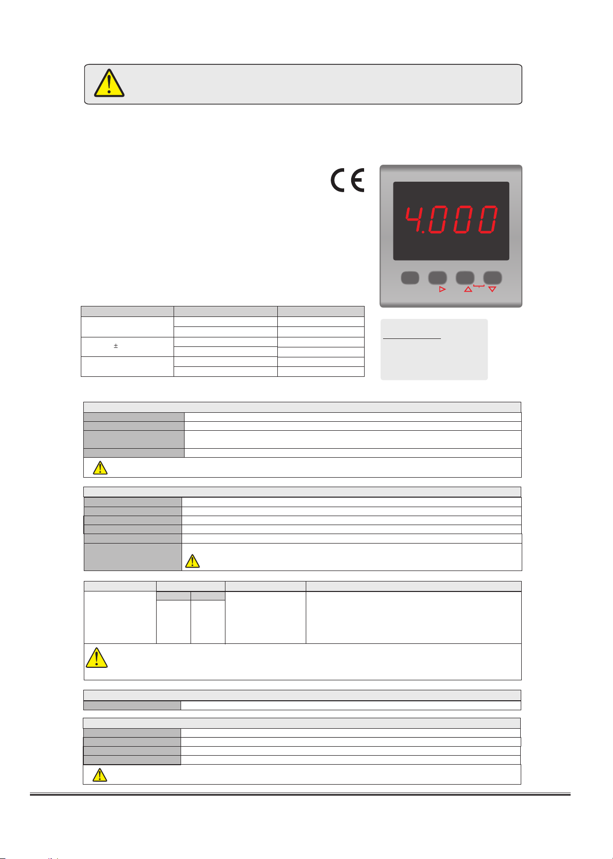
L.SCL. = Lower limit for the scale.
It can be adjusted between -1999 and
(H.SCL.-100).
See NOTE 1 for programming.
H.SCL. = Upper limit for scale.
It can be adjusted between (L.SCL. +100)
and 4000.
See NOTE 1 for programming.
S.Cod.
a.CAL.
1.CA.
10.CA.
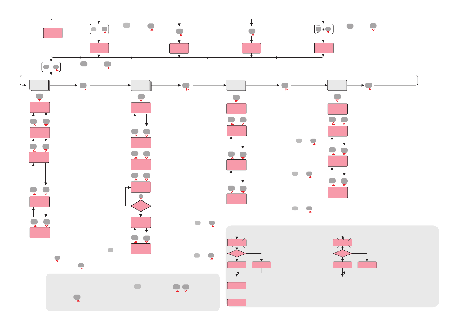
For adjusting a selected parameter first press and hold key. Then, by using keys adjustment
can be made.
Parameter adjustment method
CAL. CAL.
C.end C.end
s.err.
S.err.
C.err.
C.err.
The message on the left flashes approximately 5
seconds and calibration is completed.
The message on the left flashes approximately 5
seconds and calibration is completed.
If calibration is error free, the message
C.End appears . However,
if it is wrong, the message S.Err.
appears for 1 seconds and the program
is shifted to the next step.
for 1 seconds If calibration is error free, the message
C.End appears . However,
if it is wrong, the message C.Err.
appears for 1 seconds and the program
is shifted to the next step.
for 1 seconds
If the difference between the reference voltages or currents applied for the calibration of H.inP. and L.inP. is lower than one
half of the full scale, this error message appears on the display.
For example: Assume that the selected input type is 0-1V. In this case, if the difference voltages
applied for calibration of H.inP.and L.inP. is lower than 0.5V, this error message appears.
between the reference
If the reference voltage or current applied to the input for calibration is too high or too low, this error message appears.
ERROR MESSAGES
CAL okey? CAL okey?CAL okey?
Evet Evet
Hayýr Hayýr
NOTE 2 NOTE 3
If first and then keys are pressed together.
programming mode is entered.
U.opt. d.Cal. SeCU.
d.pnt.
Cal.t.
l.sCl.
H.sCl.
l.inp.
H.inp.
i.typ. = Input type.
Input type can be selected as 0-20mA,
4-20mA, 0-1V or 0-10V.
See NOTE 1 for programming.
dSP.C. = Display configuration.
Selectable as PrcS. or Pr.Un. . If PrcS. is
selected, process value appears. If Pr.Un.
is selected, process value and then
measurement unit are displayed 4 and 2
seconds successively.
See NOTE 1 for programming.
RAtE = Sampling rate.
Measurement is performed at each 200ms.
However,
for FASt rate, each measurement is displayed.
for SLo.1 rate, the average of 4 successive
measurements is displayed.
for SLo.2 rate,
for SLo.3 rate,
the average of 8 successive
measurements is displayed.
the average of 16 successive
measurements is displayed.
See NOTE 1 for programming.
Hold = Display holding parameter.
Selecting NonE , this parameter becomes
inactive.
Selecting Lo. , always the minimum
measured value is displayed.
Hi. ,Selecting always the maximum
measured value is displayed.
CAL.t.=U.ýnP.
Evet
Hayýr
Unit = Measurement unit.
A constant, a message etc. to be displayed
can be entered. If a decimal point is desired,
it should be included before entering the
character.
For including decimal point first, then,
keys are pressed and held together. And
then, by using key decimal point can be
adjusted.
d.Cnf.
i.typ.
rate
Hold
dsp.C.
Unit
At this state, the reference voltage or current
that corresponds to L.SCL. parameter is applied
to the input.
To initialize calibration, first then
keys are pressed together and held until ‘ '
message appears. See NOTE 2.
CAL
At this state, the reference voltage or current
that corresponds to parameter is applied
to the input.
To initialize calibration, first then
keys are pressed together and held until ‘ '
message appears. See NOTE 2.
H.SCL.
CAL
A.CAL. = Current calibration.
At this state, 20.000 mA current is applied to the
input of the device.
10.CA. = 10V input calibration.
At this state, 10.000V is applied to the input of
the device.
1.CA. = 1V input calibration.
At this state, 1.0000V is applied to the input of
the device.
are pressed together,
measurement unit appears. See
Unit parameter for programming.
If first and then keys
are pressed together, the
maximum and the minimum
measurement values become
equal to the measured value at
that time and the message
.
Res.
appears on the display
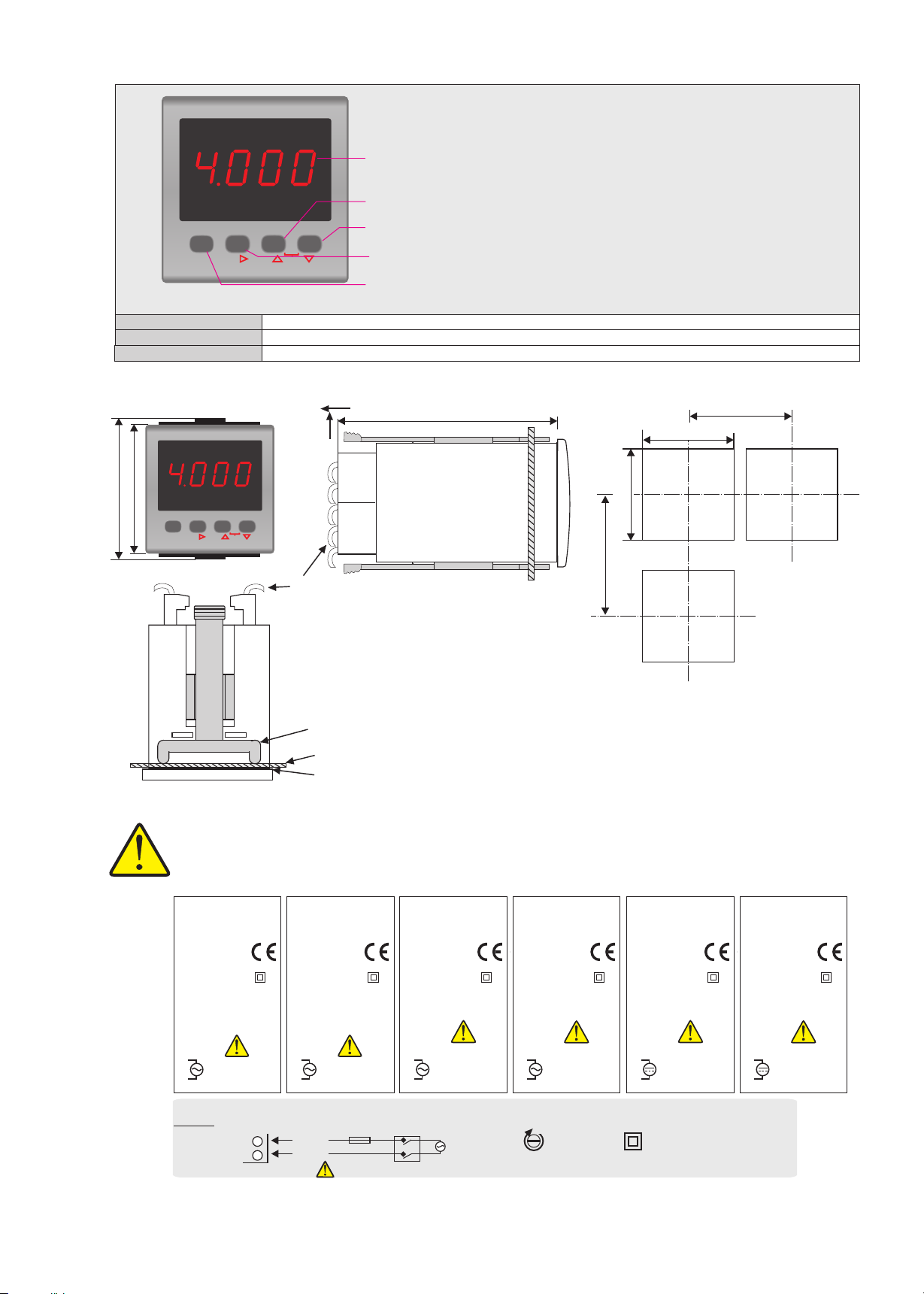
Pressing this key the minimum
measured value up to that time
appears.
Pressing this key the maximum
measured value up to that time
appears.
The minimum
measured value
The maximum
measured value
Measurement unit 870 1453
Bar.
&
Programming mode
&
3/3
MAX.
UNIT
MAX.
UNIT
MAX.
UNIT
MAX.
UNIT
MAX.
UNIT
MAX.
UNIT
RESET
RESET
RESET
RESET
MAX.
UNIT RESET
MAX.
UNIT RESET
RESET
RESET
RESET
RESET
RESET
PRG
RESET
MAX.
UNIT
SHIFT
SET
MAX.
UNIT
MAX.
UNIT
MAX.
UNIT
MAX.
UNIT
MAX.
UNIT
RESET
RESET
RESET
RESET
RESET
RESET
MAX.
UNIT
SHIFT
MAX.
UNIT
SHIFT
SET
For initializing calibration, first then
keys are pressed together and held until ‘ '
message appears. See NOTE 3.
CAL
To initialize calibration, first then
keys are pressed together and held until ‘ '
message appears. See NOTE 3.
CAL
To initialize calibration, first then
keys are pressed together and held until ‘ '
message appears. See NOTE 3.
CAL
MAX.
UNIT
SHIFT
SET
MAX.
UNIT
SHIFT
SET
MAX.
UNIT
SHIFT
SET
SET
RESET
RESET
UNIT
MAX.
UNIT
MAX.
UNIT
SHIFT
SET
SHIFT
SET
MAX.
UNIT
MAX.
UNIT
PRG
MIN.
PRG
MIN.
RESET
PRG
MIN.
PRG
MIN.
PRG
MIN.
SHIFT
SET
SHIFT
SET
SHIFT
SET
SHIFT
SET
Run mode
MAX.
UNIT RESET
PRG
MIN.
Measurement
value
1000
Res.
EI741A-E-05
IF first, and then keys
NOTE 1
If increment key is pressed and held 0.6 seconds, the value of the selected parameter changes rapidly. If
waited enough, the value increases 100 at each step. After 1 second following the release of the key, initial
condition is returned. The same procedure is valid for the decrement key.
MAX.
RESET
MIN.
Other sisel Measuring Instrument manuals
Popular Measuring Instrument manuals by other brands

Thermo Electron
Thermo Electron Orion 920Aplus quick start guide

Hubbell
Hubbell CHANCE PSC4033710 operating instructions

La Crosse Technology
La Crosse Technology EA-3010 operating manual

APG
APG PG-2000 Operator's manual

turck
turck IMXK12-AO01 Series quick start guide

Katronic Technologies
Katronic Technologies KATflow 150 operating instructions