ConF Out1
tYpE
d.pnt
Opnt
Adr5
bAUd
UPLL
HYSU
dLYU
LOLL
HYSL
Samping Time
If 1 ( 1 ) is selected ; sampling time of the measurement is 250ms,
If 2 ( 2 ) is selected, it is 500ms. If 3 ( 3 ) is selected, it is 750ms.
If 4 ( 4 ) is selected, it is 1 second.
Device Address
It can be adjusted between 1 - 247 .
Baud Rate
It can be adjusted as OFF, 1200, 2400, 4800, 9600, 19200,
38400, 57600 and 115200 .
OtYp
dLyL
Out1 Output
It can be adjusted as n.o. or If is selected,
incase of alarm, out relay is activated.
N.c. n.o
Upper Limit Value
It can be adjusted between minimum and maximum
scale that is specified with c.tr.r parameter. This
parameter can’t be lower than
( ) l0ll - HY5U - HY5L
Hysteresis Value for Upper Limit
It can be adjusted between 0 and ctrr /5
parameter. This parameter can’t be higher than
( - - HY5L ).
When ctrr changed, HY5U gets the value
of 0.1 .
Upll l0ll
Delay Time for Upper Limit Alarm
It can be adjusted between 0 and 900 .
Lower Limit Value
It can be adjusted between lower scale and upper
scale that is specified with c.tr.r parameter.
This parameter can’t be higher than (
) value.
UPLL -
HY5U - HY5L
Hysteresis Value for Lower Limit
It can be adjusted between 0 and Ctrr /5 . This
parameter can’t be higher than ( - -
) value. When ctrr is changed, HY5U
gets the value of 0.1 .
UPLL L0LL
HY5U
Delay Time for Lower Limit Alarm
It can be adjusted between 0 and 900 seconds.
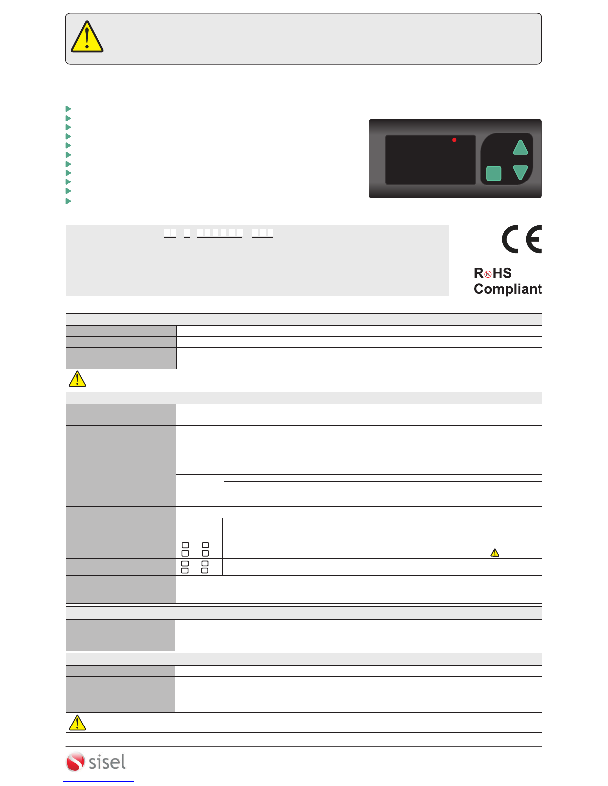
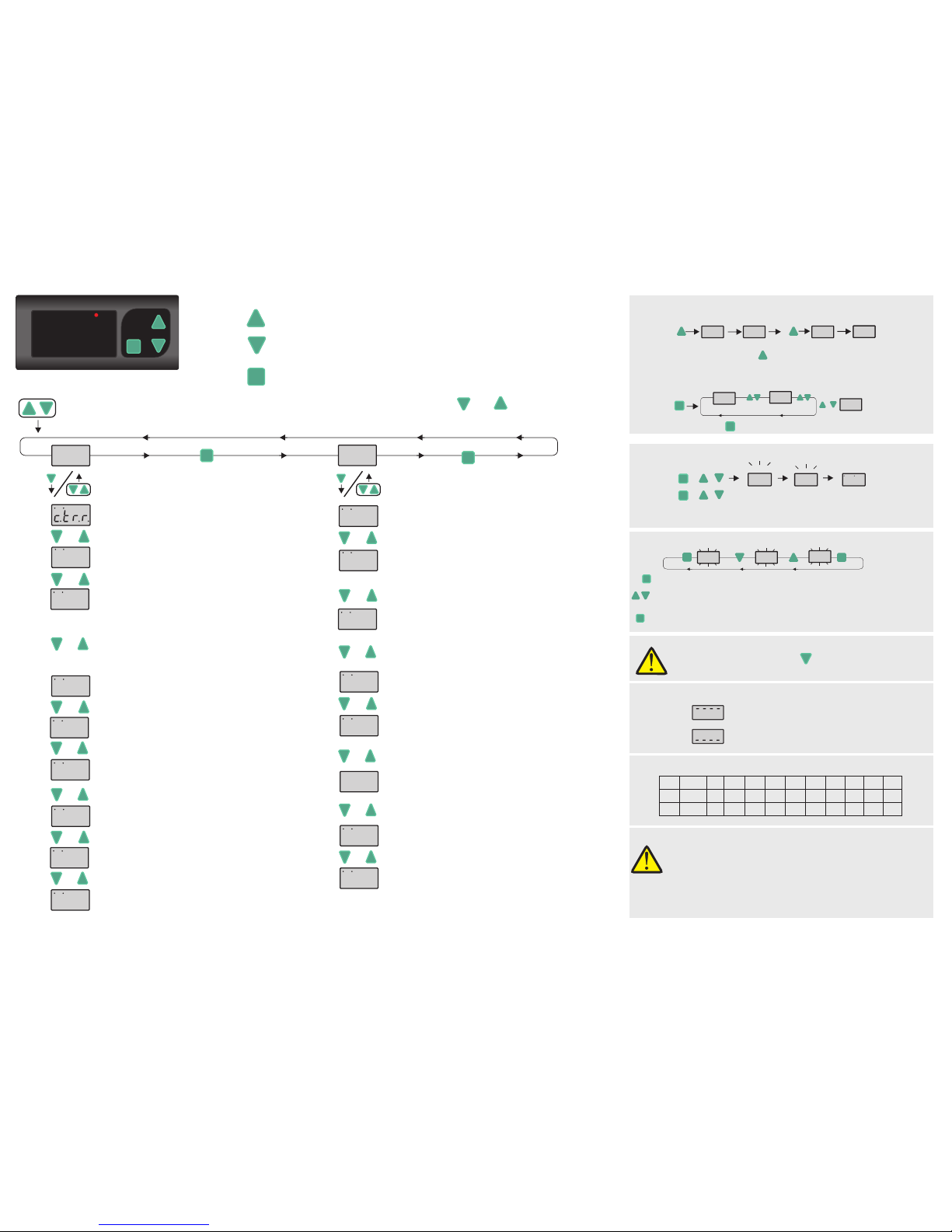
SET
SETTING UP THE PARAMETERS
tYPE dC ACdC
If key is pressed, the current value of the parameter appears by flashing on the display.
SET
After the setting up the parameters, if set key is pressed again, adjusted parameter
name appears on display.
By using “UP” or “DOWN” navigation keys, selected parameter can be adjusted to
the desired value.
Measured Value
L0C UL0C
0.00 0.00
LOCKING & UNLOCKING KEYPAD
SET
UPLL LOLL
0.00
0.00
+
By pressing to key for 3 seconds, quick menu is entered.
QUICK MENU
&&01.01 2015
Year
Day.Month
If these keys are pressed and held together, revision
date appears as day, month and year.
SET
0.00
REVISION NUMBER
SET
SET
Powered on device by pressing key. dPAr message appears
on display and device reset to default settings.
Measured current value is higher than maximum scale.
Measured current value is lower than minimum scale.
iIncludes in R extension devices.
SETSET
EPA242
ENDA
OUT AC DC ACDC
A
0.000
& &
SET
SET
&
3/4
&&
SET
While revision information displayed and if one of the pressed key
is released, measured value is displayed again.
Used for displaying and configuring the selected parameter value.
Programming
key
Used for increasing the setpoint value and changing parameters.
When held down for a few seconds, configured numeric value increases faster.
When held down for a few seconds, configured numeric value increases faster.
Used for decreasing the setpoint value and changing parameters.
Increment
key
Decrement
key
SET
If these keys are pressed and held for 3 seconds, “Programming Mode” is entered or it returns to “Running Mode”. If and keys are pressed
while parameter names are displayed, than it returns to measured value.
PROGRAMMING MODE
Current Conversion Ratio
It can be adjusted between 5.00(/5) and (/5). If this parameter
changes, upper limit value is set to maximum scale ,minimum limit value is
set to minimum scale and hysteresis values are set to 0.1 .
9999
Measuring Method
It can be adjusted to , or ac dc acdc. LEDs on the top of the display
indicates the adjusted measurement method.
Decimal Indicator
0
Decimal point moves automatically according to displayed value on
the screen.
If measured value is lower than 10, it can be shown as
(0.0 0) , (0.00) , (0.0) or (0).
If measured value between 10 and 100, it can be shown as
(0.00) ,(0.0) or (0).
If measured value between 100 and 1000, it can be shown as
(0.0) or (0) .
Measured Value
Measured Value
Measured Value
DEFAULT SETTINGS
ERROR MESSAGES
Delay Time for Initial Upper Limit Alarm
It can be adjusted between 0 and 900 seconds.
EPA242-E-03-161212
5dly
In “Running Mode” , by pressing to key for 3 seconds, keypad locked or unlocked.
SET
ityP
turn
AtyP
Input Type ( In devices with input type "CT" )
Can be adjusted to Ct20 , CT30 and 5HNt values.
If 5Hnt is selected, 60mV input terminal must be used.
Number of Windings ( In devices with input type "CT" )
Number of windings of the current cable getting through the CT20/30
current transformer.
Please see "CT20/30 Current Transformer & Windings" chart on
the right of this page.
turn
Iin max(A)
1 2 3 4 5 6
CT20
CT30
300
Iin max(A) 150 100 75 60 50
120 60 40 30 24 20
7 8 9 10
42,8 37,5 33,3 30
17,1 15 13,3 12
CT20/30 Current Transformer & Windings Chart
Analog Output Status ( In devices with output type "Analog" )
Can be adjusted to 0 - 20 , 4 -20 , 0 -10 and 1 - 5 values.
Note :
If ityp = 5hnt , turn parameter is not appears.
If ityp = Ct20 or Ct30 , ctrr parameter is not appears.
Note :
Before setting the relay parameters, the operating scale must be
determined from dpnt parameter.
If dpnt , typE and Ityp parameters are changed, Upll ,
loll , Hy5U and Hy5l values must be checked.
PROGRAMMING DIAGRAM