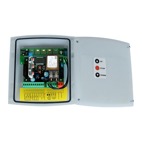
Sistemes Electrònics Progrés s.a. AGRONIC 54 User manual

1
INSTRUCTION
MANUAL
12 Vdc
INDEX
Sec. Theme Page
1. INTRODUCTION 1
2. SCREEN DATA 2
3. TECHNICAL CARACTERISTICS 2
4. DIMENSIONS 3
5. TITLE PAGE 3
6. INPUTS AND OUTLETS 3
6.1. Inputs 3
6.2. Outlets 4
7. CONFIGURATION OF THE INSTALLER
5
8. CONSULTATION 6
9. PROGRAMMING 6
10. CONFIGURATION OF THE USER 6
11. CALIBRATION 7
12. BREAKDOWS 7
13. FUNCTION CHART 8
PRESENTATION
We wish to take this opportunity to thank you for
the confidence in us which you have demonstrated in
expressing interest or acquiring Agrónic 54.
This confidence, for our part, stimulates our
efforts to meet and surpass the expectations of our
clients to justify the traditional quality of our products.
This Manual will allow you to see the capacity of
the unit as well as its installation and use.
However, if after reading this you still have any
doubts, contact us and we will happily answer them.
1. INTRODUCTION
Agrónic 54 is a unit which regulates both the
electrical conductivity (EC) of irrigation water, injecting
2 possible fertilisers, and its pH, injecting acid or base.
There are 3 formulas or programmes, which are
started by external orders received by the
corresponding inputs.
There are 2 versions, according to the way in
which the dosage is done: one with “pulsed injection”,
which works on the solenoids, another one with
“analogical injection”, which works on frequency
variators.
In the “by pulsed injection” version, to maintain
the CE, the unit applies every certain seconds, a dose
of every fertiliser, which is related to the desired
proportion between fertilisers and the programmed
reference. To maintain the pH the unit works in a
similar way.
In the “analogical injection” version, to maintain
the CE and/or the pH, the unit changes the injection
speed of the engines until it gets the programmed
references.
In the version with pulsed injection, there are
outlets for 2 fertilisers and 1 acid or base.
In the version with analogical injection (0-10
Vdc), there is an outlet for fertiliser and another one for
acid or base.
In both versions, there is also a general outlet
and another one for alarm and/or agitator.
Feeding of the unit at 12 Vdc and outputs as well
to 12 Vdc.
Outlets at 12 Vdc in the version with pulsed
injection and at 0-10 Vdc in the version with analogical
injection.
There are 3 inputs for the start of the fertilisation
programmes and 1 input to detect breakdowns.
There is also 1 input for the conductivity sensor
and 1 for the pH sensor, with a transmitter, which is
integrated in the unit circuitry.
The calibration of sensors is done with the
keyboard.
It is possible to programme three different crops.
The EC reference, pH reference and the proportion of
two fertilisers to be applied (this is in the version with

2
pulsed injection) are given to every one of the three
programmes.
There are independent EC and pH alarms, being
possible to configure the high value, the low one and
the delay in the detection of an irregularity.
Start and stop times are programmable for the
preagitation, agitation and alarm.
It is easy to use and programme by means of
three keys and a LC screen with 14 millimetre-high
digits.
The unit is located in a poly-carbonate closed
box. Agrónic 54 follows the CE guidelines.
2. SCREEN DATA
Information is displayed on the screen in the
following way: the first two digits indicate the code in
which we are in. The following block of digits always
gives information about the electrical conductivity or
fertiliser 1, while the last block of digits makes
reference to the pH or fertiliser 2.
Use the “C” key to go from one code to the next
one. If you keep pressing this key, the code will
change rapidly.
Use the “+” and “-“ key to modify the values
which are displayed on the screen. These keys will
increase or decrease the active value, which is
displayed in that moment. If you keep pressing the
key, it increases or decreases rapidly.
3. TECHNICAL CHARACTERISTICS
Feeding
Power source 12 Vdc
Energy consumption Average consume: 8.5VA
Input fuse 4 A, F type, 250 V (fast)
Outlets Inputs
Number 5Number 4
Type Relay, Triac optolinked Type Optolinked
Environment Weight(approximate) Memory backup
Temperature 0º C a 45º C 1 Kg. Parameters,
programmes It cannot be
erased
Humidity < 85 %
Height 2000 m.
Pollution Grade II
DECLARATION OF CONFORMITY
It follows the 89/336/CEE Guidelines for the Electromagnetic compatibility and the
73/23/CEE Guidelines of Low Tension for the Fulfilment of the Product Security. The
fulfilment of the following specifications was demonstrated as indicated in the Official Diary
of the European Communities.
Symbols which can be displayed on the product Double insulation

3
4. DIMENSIONS 5. TITLE PAGE
All measures in mm.
6. INPUTS AND OUTLETS
6.1. INPUTS
The unit has four digital inputs (D1,D2,D3,D4).
Three of them work as switches (D1,D2 and D3),
starting or stopping the corresponding programme,
while the fourth one is a breakdown input (D4).
The activation of inputs is done through their
connection to the common.
A time for the detection delay can be
configured for every input, but the deactivation is
immediate.
The pH and conductivity reference, as well as
the proportion between fertilisers can be configured
for every input or programme 1, 2 and 3. If more than
one input is activated at the same time, the
programme which has priority is the one with the
lowest cardinal number.
Input 4, breakdown, is only taken into account if
a programme is working.
The unit also has an input for pH sensor
(terminal type BNC) and another one for conductivity
sensor.

4
SECTION OF THE UNIT SUPERIOR BOARD
VERY IMPORTANT: The grid must be
connected to the box terminal of the unit.
6.2 OUTLETS
The unit has 5 outlets, 2 of them are digital and
the other 3 can be digital or analogical, depending
on the chosen version.
Outlets are protected by a 2.5 A fuse Type F
(fast). Replace it with a similar one if it fuses.
SECTION OF THE UNIT INFERIOR BOARD
-S1, S2 and S3: Digital outlets for the injection of
acid or base and fertiliser by pulses. The acid or
base electrovalve is connected to S1, the
fertiliser number 1 electrovalve to S2 and the
fertiliser number 2 electrovalve to S3.
-Electrically, the electrovalves will be connected
directly to the outlets without any relay in
between and hydraulically they will be
connected to the venturis or to the magnetic
pumps.
-A1, A2: Analogical outlets from 0 to 10 volts to
connect to frequency variators or regulators. It is
important neither to short-circuit these signs nor
to put the cables near power lines. Outlet A1
corresponds to fertiliser and A2 to acid or base.
The symbol is the common outlet or 0
volts.

5
-S4: Digital outlet, which is activated during the
whole irrigation, except when there is a
breakdown.
-S5: Digital outlet used both for the start and stop
of agitators and for breakdown detection. For a
shared use of both functions, it is necessary to
use a relay activated by the general outlet. If it is
activated, the agitators will work, but if it is
deactivated, the alarm device will work.
7. CONFIGURATION OF THE INSTALLER
This configuration must be done by the unit
installer. Press the “+” and “-“ keys at the same time
to access it. Press the “C” key to go to the following
code. Press the “+” and “-“ keys to change the
values. Press the “C” key until the C0 code is
displayed to go back to CONSULTATION.
-Code 00: Delay until the first regulation. Indicate
the time in seconds that the programmer must
wait to calculate the regulation when a
programme is started. During this time, the % of
applied injection will be the one memorised in
the last irrigation. This allows the injection
stabilisation. The value must be between 0 and
250.
-Code 01: Reaction delay. Indicate the time in
seconds that the programmer must use to carry
out the adjustment to be done. The maximum
time is 5 seconds. Time 0 indicates that the
adjustment must be done as soon as it is
detected.
-Code 02: Self adjustment delay. Indicate the
time in seconds that must go by between a self-
adjustment attempt and the next one. The self-
adjustment is a small increase or decrease of
the % of injection which is introduced when the
sensor value is outside the programmed
reference value but within the allowed error.
The minimum time is 4 seconds and the
maximum is 15.
-Codes 03, 04 and 05: Proportional bands. The
limits, within which the % of injection will be
calculated, must be indicated in these three
codes, one for every programme. The lower the
limit, the more abrupt the changes will be when
trying to obtain the desired reference. The value
can be between 0 and 9.9, although the normal
is 2.0.
-Code 06: Modulation cycle (*). Indicate, in
seconds, the frequency in which the injection
impulses will be repeated. A suitable value
would be between 2.0 seconds and 4.0
seconds, although it can go from 2.0 to 9.9
seconds.
-Codes 07, 08, 09 and 10: Delay. Indicate, in
seconds, the time that has to go by from the
moment the activation of an input is detected
until the programmer takes it into account. The
value must be between 0 and 250.
-Code 11: Acid o base. In this code it can be
selected how it will work the pH regulation in
the irrigation water, by means of acid or base. If
it leaved the value to 0 it will work like an acid,
and if it is modified with the “+” key and leaved
to 1 it will work like a base. Then, it will be
determinate if there is an acid or base tank.
(*) In the “by impulse” version, to maintain the CE, the unit
applies every certain seconds, a dose of every fertiliser, which is
related to the desired proportion between fertilisers and the
programmed reference. To maintain the pH the unit works in a
similar way. In the “analogical” version, to maintain the CE
and/or the pH, the unit changes the injection speed of the engines
until it gets the programmed references.

6
8. CONSULTATION
The first two codes of the programmer
correspond to consultations of the unit state (C0 and
C1).
-Code C0: It shows the conductivity and pH
reading that reach the unit through the sensors.
If a breakdown takes place, the programmer
shows this code and the alarm origin
(programme number) intermittently, and the
reason for it (high or low conductivity, high or
low pH, breakdown input). For further
information read the section BREAKDOWNS.
C0
2.
4
6. 5
Reading of the
conductivity sensor
Reading of the
pH sensor
-Code C1: It shows the percentage of fertiliser
injection, which has the highest proportion, as
well as the percentage of acid or base, which is
being injected.
-
C1
2
1
3
3
% of fertiliser
being injected
% of acid or base
being injected
9. PROGRAMMING
The codes that go from C2 to C7 are used to
define every programme, having to specify the
desired level of conductivity and pH, as well as the
relationship between the injection of the two
fertilisers.
Every code is divided into two sections. The first
one corresponds to values of conductivity or values
from the first fertiliser, while the second one
corresponds to values of pH or of the second
fertiliser. Press the “C” key to change section or
code and the “+” and “-“ keys to increase or
decrease the value of the section which is active, that
is to say the one which has a blinking point on its
left. A point showed just after the code means that
the programme is activated.
-Codes C2, C3 and C4: Indicate the desired
reference value for conductivity (value from 0 to
9.9) and pH (value from 0 to 9.9) which is to be
reached when programme 1, 2 and 3 are
activated. The value 00 means that this part is
not to be regulated.
C
2.
2.6
6.
3
Activated
programme
Conductivity reference
(programme 1)
pH reference
(programme 1)
-Codes C5, C6 and C7: Indicate the desired
proportion between the fertilisers of every one
of the three programmes.
C
6
3
0
1
1
Non activated
programme
Proportion of fertiliser
1. (programme 2)
Proportion of fertiliser
2. (programme 2)
10. CONFIGURATION OF THE USER
In this section we can find the parameters
which allow you to adjust the working of the unit, as
well as the sensor calibration. To access this section,
press the “C” and “+” keys at the same time when
the programmer is at code C0 of consultation. If no
input is activated, the programmer goes to sensor
calibration; otherwise, it goes directly to the first
configuration code (code 04).
Press the “C” key to go from one code to
another. Use the “+” and “-“ keys to change values.
Press the “C” key until the code C0 appears to go
back to consultation.
Codes from 00 to 03, corresponding to
calibration are explained in the CALIBRATION
section.
-Code 04: EC high alarm. Indicate the value at
which the indicated reference has to be
surpassed (between 0 and 9.9) in order to
activate the alarm because the conductivity
level is too high.
-Code 05: EC low alarm. Indicate which value
(between 0 and 9.9) can be reached below the
desired reference in order to activate the alarm
because the conductivity level is too low.
-Code 06: pH high alarm. Indicate the quantity of
points (between 0 and 9.9) the indicated
reference can be surpassed in order to activate
the alarm because the pH level is too high.
-Code 07: pH low alarm. Indicate the quantity of
points (between 0 and 9.9) below the indicated
reference must be reached in order to activate
the alarm because the pH level is too low.

7
-Code 08: Delay in the EC alarm detection.
Indicate the number of seconds during which
conductivity must be at an alarm level before its
activation. The value must be between 0 and
999.
-Code 09: Delay in the pH alarm detection.
Indicate the number of seconds during which
pH must be at an alarm level before its
activation. The value must be between 0 and
999.
-Code 10: Pre-agitation. Indicate the number of
seconds during which the agitator must be
working before injection is started. The value
must be between 0 and 250.
-Code 11: Agitator working. Indicate the number
of seconds the agitator must be working in the
agitation cycles, which take place during the
fertilisation. The value must be between 0 and
250.
-Code 12: Agitator at stop. Indicate the number
of seconds the agitator must be at stop in the
agitation cycles, which take place during the
fertilisation. The value must be between 0 and
250.
-Code 13: Alarm working.Indicate the number of
seconds the alarm must be working in the cycle
of alarm signal. The value must be between 0
and 250.
-Code 14: Alarm at stop. Indicate the number of
seconds the alarm must be at stop in the cycle
of alarm signal. The value must be between 0
and 250.
11. CALIBRATION
In the configuration of the user, codes from 00
to 03 are used to calibrate sensors. On entering in
everyone of the codes, the code and value which is
expected from the sensor appears for a few
seconds. After these seconds, the screen blinks and
displays the reading, which is being obtained from
the sensor. If the reading is stable enough and
similar to the desired one, the screen stops blinking,
indicating that the sensor has been calibrated. If you
press the “+” and “-“ keys simultaneously the unit is
forced to accept the value which is displayed at this
moment.
If the calibration of sensor is not to be done,
press the “C” key during the initial seconds or press
the “C” key until the code changes, when the screen
is blinking.
In order to have a good calibration, the sensor
and the liquid have to be as close as possible to
25ºC degrees. Then, the liquid value and the
automatic compensation that the sensor have will be
correct. If the irrigation water is cooler than 25ºC the
sensor it should be taken out for several minutes
because the sensor has and inertia to the
temperature changes.
The calibration codes go in pairs. So, codes 00
and 01 are used to calibrate the conductivity sensor,
while codes 02 and 03 correspond to the calibration
of the pH sensor. If a suitable calibration is not done
in the first code, the second one does not appear.
So, to do a valid calibration of the sensor, it is
necessary to do the two codes, which correspond to
the sensor correctly.
12. BREAKDOWNS
When the unit detects a breakdown, because a
non desired level of conductivity or pH has been
reached or because input 4 has been activated, the
programme stops automatically and injection also
stops. The screen displays the consultation code C0
and the information about the reason of the
breakdown in a blinking way. The programme will
not be started again until, the breakdown is not
deactivated by pressing the “C” key.
Option code Origin of the alarm
(EC, PH, E4)
C0
A
1
P
H
_
Indicator of the
alarm and nº of
programme
Type of alarm
(low, a dash below,
high, a dash above)

8
13. FUNCTION CHART
R-1078
Table of contents
Other Sistemes Electrònics Progrés s.a. Control Unit manuals
Popular Control Unit manuals by other brands

Keyautomation
Keyautomation CT1RD Instructions and warnings for installation and use

Kieback&Peter
Kieback&Peter BMD1200 Product description

Timeguard
Timeguard TS800B operating instructions

Alfalaval
Alfalaval Unique Mixproof Horizontal Tank instruction manual

Vari Lite
Vari Lite PSV operating instructions

Paradox
Paradox IP150 user manual