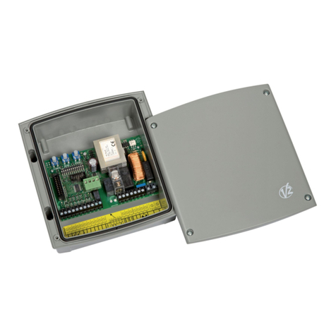
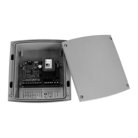
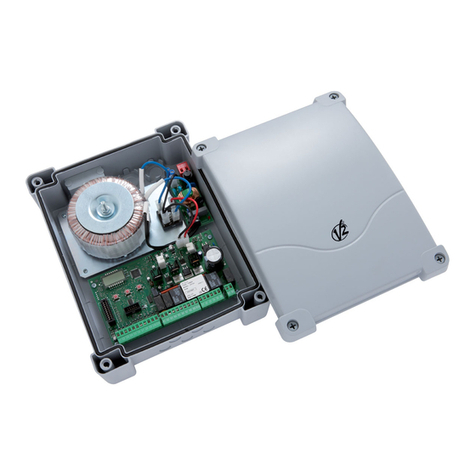
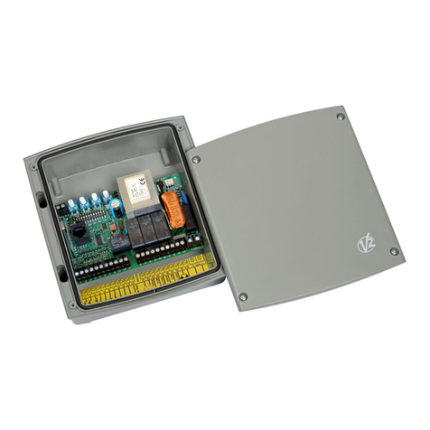
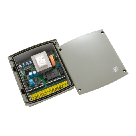
V2 EASY-TOP User manual

EASY-TOP
L n. 312
ED Z. 31/07/2014
V2 S.p.A.
Corso Principi di Piemonte, 65/67
12035 RACCON G (CN) TALY
tel. +39 01 72 81 24 11 - fax +39 01 72 84 050
[email protected] - www.v2home.com
CENTRA E DI COMANDO DITA E
PER SERRANDE AVVO GIBI I
DIGITA CONTRO UNIT FOR
RO ER SHUTTERS
ARMOIRE DE COMMANDE DIGITA E
POUR STORES
CUADRO DE MANIOBRAS DIGITA
PARA PERSIANAS ENRO AB ES
QUADRO E ÉCTRICO DIGITA
PARA ESTORES DE ENRO AR
DIGITA STEUERUNG FÜR RO TORE
DIGITA E STUURCENTRA E VOOR RO UIKEN
I
GB
F
E
P
D
N

ENG ISH
9
IMPORTANT REMARKS
For any installation problem please contact our Customer Service
at the number +39-0172.812411 operating Monday to Friday
from 8:30 to 12:30 and from 14:00 to 18:00.
V2 has the right to modify the product without previous notice;
it also declines any responsibility to damage or injury to people
or things caused by improper use or wrong installation.
m Please read this instruction manual very carefully before
installing and programming your control unit.
• This instruction manual is only for qualified technicians, who
specialize in installations and automations.
• The contents of this instruction manual do not concern the
end user.
• Every programming and/or every maintenance service should
be done only by qualified technicians.
AUTOMATION MUST BE IMP EMENTED IN COMP IANCE
WITH THE EUROPEAN REGU ATIONS IN FORCE:
EN 60204-1 (Machinery safety. electrical equipment
of machines, part 1: general rules)
EN 12445 (Safe use of automated locking
devices, test methods)
EN 12453 (Safe use of automated locking
devices, requirements)
• The installer must provide for a device (es. magnetotermical
switch) ensuring the omnipolar sectioning of the equipment
from the power supply. The standards require a separation of
the contacts of at least 3 mm in each pole (EN 60335-1).
• After making connections on the terminal board, use one
hose clamp to fix dangerous voltage wires near the terminal
board and another hose clamp to fix safety low voltage wires
used for accessories connection; this way, in case of accidental
detachment of a conducting wire, dangerous voltage parts
will not come into contact with safety low voltage ones.
• The plastic case has an P55 insulation; to connect flexible or
rigid pipes, use pipefittings having the same insulation level.
• nstallation requires mechanical and electrical skills, therefore
it shall be carried out by qualified personnel only, who can
issue the Compliance Certificate concerning the whole
installation (EEC Machine Directive 89/392, Annex A).
• The automated vehicular gates shall comply with the
following rules: EN 12453, EN 12445, EN 12978 as well as
any local rule in force.
• Also the automation upstream electric system shall comply
with the laws and rules in force and be carried out
workmanlike.
• The door thrust force adjustment shall be measured by means
of a proper tool and adjusted according to the max. limits,
which EN 12453 allows.
• Connect the earthing lead of the motors to the
electricity grid earth system.
• Observe all necessary precautions (e.g. anti-static
bracelet) for handling parts sensitive to
electrostatic discharges.
DEC ARATION OF CONFORMITY
V2 S.p.A. hereby declare that products EASY-TOP conform to the
essential requirements established in the following directives:
-2004/108/CEE (EMC Directive in accordance with standards
EN 55014-1, EN 55014-2, EN 61000-3-2, 61000-3-3)
- 2006/95/CEE (Low Voltage Directive in accordance with
standards EN 60335-1 + EN 60335-2-103)
- ROHS2 2011/65/CE
Racconigi, lì 28/01/2014
V2 S.p.A. legal representative.egale della V2 S.p.A.
Cosimo De Falco
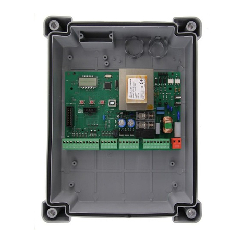
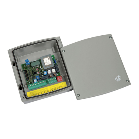
DESCRIPTION OF THE CONTRO UNIT
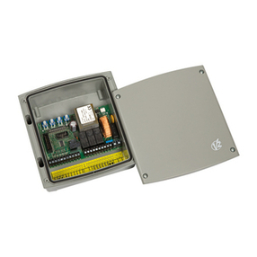
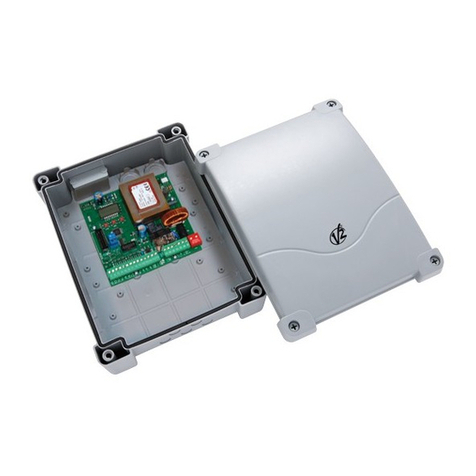
The EASY-TOP digital control unit is an innovative V2 product
that guarantees safety and reliability for the automation of roller
shutters.
• 230 Vac output for 1 single-phase motor
• 230 Vac output for flashing light or timed courtesy light
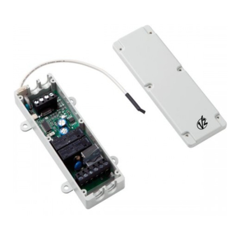
• Plug-in adaptor for modular radio receiver MR2
• nput for key switch or pushbutton (START)
• nput for separate UP/DOWN commands
• nput for safety pushbutton (STOP)
• nput for safety photocell with automatic operating test
(PHOTO)
• Sensitive edge safety input (EDGE): can connect to a
mechanical or resistive rubber edge with automatic operation
test or to an optical edge with 30V DC power supply and by
adjusting the transmitter power
• nputs for limit switches (FCA-FCC) that can be used as an
alternative to the EDGE and F RE inputs
• nput for fire emergency or theft (F RE)
• Monitoring of the inputs on the display
• Logic of operation and programmable work times using the
keyboard and display
• Possibility of operating in DEAD MAN mode
TECHNICA
SPECIFICATIONS 230V models 120V models
Power supply 230V / 50Hz 120V / 60Hz
Max motor load 1100W 600W
Max accessories load
30 Vdc 3W 3W
Working temperature -20 ÷ +60 °C -20 ÷ +60 °C
Protection fuse F1 = 5A delayed F1 = 5A delayed
Dimensions 170 x 185 x 70 mm
Weight 800 g
Protection P55

ENG ISH
10
EECTRIC CONNECTIONS
mWARNING: Normally closed inputs STOP ( 2), PHOTOCE ( 5), EDGE ( 6), FIRE ( 7), if not used must be bridged through
the COMMON terminal ( 3 - 8)

ENG ISH
11
1 START/UP. N.O. contact
2 STOP. N.C. contact
3 COMMON (-)
4 DOWN. N.O. contact
5 PHOTOCELL. N.C. contact
6
EDGE. N.C. contact
(Safety edge - parameter in5 = oFF)
FCA. N.C. contact
(Opening limit switch - parameter in5 = on)
7
F RE. N.C. contact
(Alarm - parameter in5 = oFF)
FCC. N.C. contact
(Closing limit switch - parameter in5 = on)
8 COMMON (-)
9 Adjustment of the power for OPT CAL SAFETY EDGE
10 30 Vdc power output for photocells and
other accessories
11 30 Vdc power supply for functional test
TX photocell
E1 - E2
Flashing light 230Vac / 120Vac
(parameter ou1 = oFF)
Courtesy light 230Vac / 120Vac
(parameter ou1 = on)
E3 Motor open
E4 Motor common
E5 Motor close
N230Vac / 120Vac power supply - neutral
230Vac / 120Vac power supply - phase
A1 Antenna shield
A2 Antenna
OPTICA EDGE INSTA ATION
The EASY-TOP main control unit is configured for the installation
of one 24 Vdc powered optical edge and transmitter power
regulation.
Connect the transmitter and receiver in accordance
with the following table.
After having made the connections, power-up the main control
unit and adjust the power using the trimmer TR1 located on the
control unit so as to obtain optimal edge operation.
FIRE / A ARM INPUT
Safety input for connecting a fire or other type of alarm requiring
the immediate automatic opening of the door.
The F RE command should be connected between the F RE (L7)
and COMMON (L8) terminals.
When the F RE contact is opened, the door is opened and cannot
be closed again until the contact is reset.
NOTE: f the input is set as an alarm (in4 = oFF), when the F RE
contact is open, the port cannot be opened. f the port is already
open, it is closed.
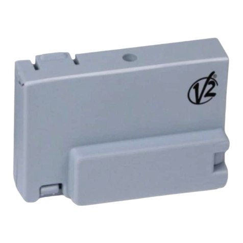
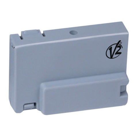
P UG IN RECEIVER
The control unit is suitable for plugging in a MR receiver.
MR module receiver is provided with 4 channels and each of
them is suitable for a command of the control unit:
• CHANNEL 1 gSTART/UP
• CHANNEL 2 gSTOP
• CHANNEL 3 gDOWN
• CHANNEL 4 gCOURTESY L GHT
mWARNING: Before programming 4 channels and
function logics read carefully the instructions of MR
TRANSMITTER RECEIVER
6 BLACK CABLE
8 BLUE CABLE BLUE CABLE
9BLACK CABLE
10 BROWN CABLE
11 BROWN CABLE

ENG ISH
12
OPERATION WITH A TIMER
The control unit allows the connection of a timer for
programming door opening and closing times.
To use this function, it is necessary to set the Lo 3 function
(see FUNCTION TAB E) on the AUTOMATIC OGIC (on) and
the Lo 5 function on the TIMER (oFF)
The timer should be connected between the START (L1) and
COMMON (L3) terminals.
Each time the timer closes the contact, the automation device
opens the door and remains paused until the contract is released.
At this point the countdown starts, for the length of the pause
time set, after which the automation device closes the door.
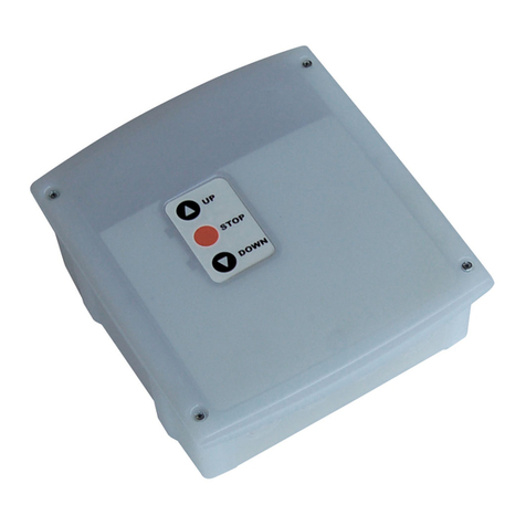
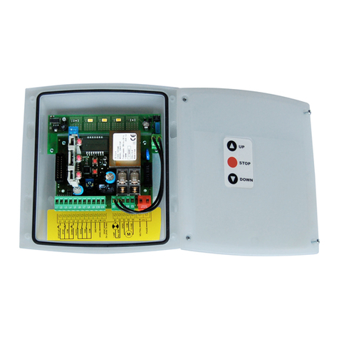
CASE WITH KEYPAD
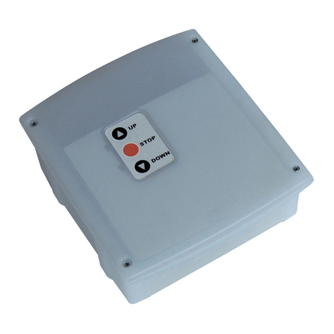
The EASY-TOP control units may be installed in cases with
external keypads (accessory codes 171224 + 171226).
To use the keypad buttons, it is essential to install adapter
171226 as shown in the figure.
Alternatively, the WES-EASY accessory may be installed (code
35B025), which besides using the keypad allows controlling the
edges by radio using the special sensors (see the WES-EASY
instructions).
The keypad buttons operate in parallel with the terminal controls.
These all remain active,
including the STOP command, and must be jumpered to ground
if not used.
Versions supplied with keypads also allow the automation device
to operate in DEAD MAN mode should the safety devices
malfunction.
By pressing and holding the button on the keypad, the
automation device is activated after 5 seconds, overriding the
safety devices; the motor stops immediately as soon as the
button is released.
NOTE: This function is also available from the terminal
board if the Lo 5 function is set to EMERGENCY
CAB E G AND ASSEMB Y
The casing can accept 4 cable glands in the special easy-break
housings. The type of cable gland is indicated in the figure.
mP EASE NOTE:
• Remove the electronic circuit board before drill the casing.
• Drill the container using a suitably sized cutter, according to
the dimensions of the cable gland.
• Fix the cable glands using the special nuts.

ENG ISH
13
CONTRO PANE
When power is on, the control unit checks that display correctly
operates by switching on all segments for 1.5 sec. 8.8.8.8.
Firmware version, e.g. Pr 1 .0, will be viewed in the following
1.5 sec.
Panel will be viewed upon completion of this test.
The control panel represents the physical status of the
terminal board contacts and of the program mode keys: if the
upper vertical segment is on, the contact is closed; if the lower
vertical segment is on, the contact is open.
The arrows to the left of the display indicate the status of the
MENU and SEL buttons.
The arrows to the right of the display indicate the status of the
shutter.
• The highest arrow lights up when the shutter is in the
opening phase.
• The central arrow indicates that the shutter is paused.
f it flashes it means that the timer for automatic closing is
active.
• The lowest arrow lights up when the shutter is in the opening
phase.
PROGRAMMING
The functions of and times of the control unit are programmed
via the configuration menu, which can be accessed and explored
using the 2 MENU and SEL keys.
• To access the programming menu, press the MENU key until
the display shows in 1
• To change the value of this parameter, press the MENU key:
the display shows the currently set value (on / oFF)
• Select the desired value with the SEL key and press the MENU
button to save the new value: the display shows in 1 again
• Press the SEL key to select the other parameters to be changed
Using the MENU and SEL keys to select and change the required
parameters: in the following pages there is a table with all
programming parameters, values selected, DEFAULT values set
and a brief description of the function.
To exit the programming menu, press the MENU key until the
display shows the control panel
f no button is pressed for 30 seconds, the control unit exits
programming mode and stores the new parameters.
To exit the programming menu and undo the changes made
during the current programming session, press the MENU and
SEL keys simultaneously until the display shows the control panel.
To load default data, when the control unit is NOT in
programming mode, press the MENU and SEL keys
simultaneously until the display shows dEF.
With the SEL key, select the default that you want to load and
press MENU to confirm.
NOTE: the control unit is supplied with the dEF1 configuration
set

ENG ISH
14
DISP AY oFF on dEF1 dEF2 dEF3
in 1 PHOTOCE ACTIVE ON Y DURING C OSING
The intervention of the photocell during the
opening stage is ignored.
The intervention of the photocell during the
closing stage causes the shutter to reopen.
PHOTOCE ACTIVE DURING OPENING AND
C OSING
The intervention of the photocell during the
opening phase causes the motor to stop.
When the photocell beam is released, the
automation starts during opening for the work
time set in parameter t i1 .
The intervention of the photocell during the
closing stage causes the shutter to reopen.
on oFF oFF
in 2 PHOTOCE TEST INACTIVE
The photocell operation test is not
performed
PHOTOCE TEST ACTIVE
Each time the control unit receives an open or
close command, the PHOTOCELL TEST verifies
that the PHOTOCELL is operating correctly.
f the test fails, the display shows - L5 -
oFF oFF oFF
in 3 MECHANICA SAFETY EDGE
The L6 input is configured to manage a
mechanical safety edge
RESISTIVE RUBBER / OPTICA SAFETY EDGE
The L6 input is configured to manage a safety
edge (resistive rubber / optical) with active
operation test.
f the test fails, the display shows - L6 -
oFF on oFF
in 4 FIRE FUNCTION
The L7 input is configured to manage a fire
alarm
A ARM FUNCTION
The L7 input is configured to manage an
anti-theft command
oFF oFF oFF
in 5 EDGE / FIRE FUNCTION
The L6 input is configured to manage a safety
edge
The L7 input is configured to manage an alarm
IMIT SWITCH FUNCTION
The L6 input is configured to manage an
opening limit switch
The L6 input is configured to manage a closing
limit switch
NOTE: f in 5 is set on the settings of the in 3
and in 4 functions, they are not considered
oFF oFF oFF
ou 1 F ASHING IGHT
Output (E1 - E2) is on intermittently (2 Hz) during
opening and closing and during pause mode, if
automatic reclosing is active
COURTESY IGHT
The output (E1 - E2) is on and fixed during
opening, pause and closure. Having completed
the operating cycle, the light remains on for the
COURTESY L GHT OFF DELAY time
oFF on on
ou 2 END OF CYC E NON-ACTIVE SIGNA
At the end of the operating cycle, the control
unit sends no signal
END OF CYC E ACTIVE SIGNA
At the end of the operating cycle, the control
unit sends a signal to the WES sensors to activate
ENERGY SAV NG mode
oFF on oFF
Lo 1 START/STOP OGIC
The START/UP input controls the STEP or
AUTOMAT C operational cycle based on the
programmed operational logic.
The DOWN input is inactive
UP/DOWN OGIC
The START/UP input always controls opening
and the DOWN input always controls closing,
independently of the operational logic
programmed.
UP + DOWN when pressed simultaneously is the
same as a STOP command
oFF on on
Lo 2 START INACTIVE WHI E OPENING
During opening, the START command
is ignored
START ACTIVE WHI E OPENING
During opening, the START command
interrupts opening (no timer is set for automatic
re-closure)
on on on
Lo 3 STEP OGIC
The start command activates an
OPEN-STOP-CLOSE-STOP-OPEN
operational cycle
AUTOMATIC OGIC
The start command activates an
OPEN-PAUSE-CLOSE-STOP operational cycle
Closure starts automatically after the pause
time set
oFF oFF oFF

ENG ISH
15
DISP AY oFF on dEF1 dEF2 dEF3
Lo 4 DEAD MAN OGIC INACTIVE
By simply using the start command, the user can
activate the automation device in opening or
closing.
The maximum duration of opening or closing
depends on the operating time set
DEAD MAN OGIC ACTIVE
The user must press and hold the start button
for the entire duration of the desired opening or
closing procedure.
The maximum duration of opening or closing
depends on the operating time set.
DEAD MAN logic may be implemented with
both Start/Stop and Up/Down logic.
The STOP command interrupts the operational
cycle, independently of the status of the control
inputs.
Hence, if the UP or DOWN button is pressed, the
action of STOP is to stop motion, and on its
release the motor DOES NOT MOVE UNT L THE
UP or DOWN NPUT S RELEASED AND PRESSED
ONCE MORE
P EASE NOTE: when the Man-Present
function is enabled, radio-controlled
operation is disabled. To activate via radio,
set the parameter Lo 7 = on
oFF oFF on
Lo 5 TIMER FUNCTION
Each time the timer closes the contact L1-L3, the
automation starts during opening and remains
paused until the contact is released.
EMERGENCY DEAD-MAN FUNCTION
f a command is rejected because of active safety,
keep the command active for 5 seconds, the
control unit then activates dead-man mode, and
the shutter moves as long as the switch is held.
When the command is suspended, the control
unit returns to the mode set.
This way, it is possible to move the shutter when
there is evidence of a fault on a safety.
oFF oFF oFF
Lo 6 THE INTERVENTION OF THE SAFETY EDGE
DOES NOT DISAB E AUTOMATIC C OSING
THE INTERVENTION OF THE SAFETY
DISAB ES AUTOMATIC C OSING
on oFF oFF
Lo 7 DEAD MAN OGIC FROM BUTTON
The dead-man logic can only be activated via
buttons (terminal board and push button panel).
DEAD MAN OGIC FROM BUTTON AND
FROM THE TRANSMITTER
The dead-man logic can be activated via buttons
(terminal board and push button panel) and from
the transmitter.
oFF oFF on
Lo 8 DEAD MAN OGIC ACTIVATED DURING
OPENING AND C OSING
DEAD MAN OGIC ACTIVATED ON Y DURING
C OSING
oFF oFF on
Lo 9 PRE-F ASHING NOT ACTIVATED PRE-F ASHING ACTIVATED
Before activating the motor during opening, the
flashing light is turned on for 1 second.
Before activating the motor during closing, the
flashing light is turned on for 3 seconds.
oFF oFF oFF
DISP AY FUNCTION AVAI AB E VA UES dEF1 dEF2 dEF3
t i 1 WORK TIME 7” - 1 0” - 1 5” - 20” - 30” - 45” - 60”
75” - 90” - 1 20”
20” 30” 30”
t i 2 PAUSE TIME 1 0” - 1 5” - 20” - 30” - 45” - 60”
90” - 1 20” - 1 80” - 250”
30” 1 5” 1 5”
t i 3 DE AYED TURNING OFF OF THE COURTESY
IGHTS
3” - 5” - 1 0” - 20” - 30” - 60”
1 20” - 300” - 600” - 1 200”
3” 1 20” 1 20”
Table of contents
Other V2 Control Unit manuals