Ebyte E52-400/900NW22S User manual

0
E52-400/900NW22S User Manual
400/900MHz 160mW TTL LoRa MESH Wireless Networking Module

Contents
Disclaimer and Copyright Notice........................................................................................................................................... 0
I.Product Description..............................................................................................................................................................1
1.1 Product Introduction................................................................................................................................................. 1
1.2 Function description................................................................................................................................................. 1
1.3 Function description................................................................................................................................................. 2
1.4 Network topology..................................................................................................................................................... 2
1.5 Application scenario................................................................................................................................................. 3
II.Specifications...................................................................................................................................................................... 4
2.1 Limit parameters.......................................................................................................................................................4
2.2 Working parameters..................................................................................................................................................4
III. Mechanical Dimensions and Pin Definition.....................................................................................................................5
IV. Recommended Connection Diagram................................................................................................................................ 7
V. Test Suite............................................................................................................................................................................ 8
5.1 Test Suite Introduction..............................................................................................................................................8
VI. Command Introduction.................................................................................................................. 错误!未定义书签。
6.1 Introduction to AT commands................................................................................................................................ 10
6.2 Command instruction set........................................................................................................................................ 10
6.3 Query instruction set...............................................................................................................................................10
6.4 Setting up the instruction set.................................................................................................................................. 12
6.5 Parameter value table..............................................................................................................................................15
6.6 Parameter Notes......................................................................................................................................................16
Ⅶ. Basic Function Introduction..........................................................................................................错误!未定义书签。
7.1 Get the main parameters of the module..................................................................................................................18
7.2 Unicast communication (Unicast).......................................................................................................................... 18
7.3 Multicast communication (Multicast).................................................................................................................... 19
7.4 Broadcast................................................................................................................................................................ 20
7.5 Anycast function (Anycast).................................................................................................................................... 21
7.6 Introduction to routing table................................................................................................................................... 22
7.7 Additional header information................................................................................................................................23
Ⅷ. Remote Configuration..................................................................................................................................................24
8.1 Introduction to remote configuration......................................................................................................................25
8.2 Introduction to remote single point configuration..................................................................................................25
8.3 Introduction to remote broadcast configuration..................................................................................................... 25
Ⅸ. Introduction to the host computer.................................................................................................. 错误!未定义书签。
Ⅹ. Hardware Design............................................................................................................................................................. 27
XI. Hardware Design............................................................................................................................................................30
11.1 The transmission distance is not ideal.................................................................................................................. 31
11.2 Modules are vulnerable to damage....................................................................................................................... 31
11.3 Bit error rate is too high........................................................................................................................................31
Ⅻ. Welding Operation Guidance........................................................................................................................................ 31
12.1 Reflow temperature.............................................................................................................................................. 32
Chengdu Ebyte Electronic Technology Co.,Ltd.. E52-400/900NW22S User Manual
12.2 Reflow soldering curve.........................................................................................................................................32
XIII. Related Models............................................................................................................................................................ 33
XIV. Antenna Guide..............................................................................................................................................................33
Revision History................................................................................................................................................................... 34
About Us............................................................................................................................................................................... 34

0
Disclaimer and Copyright Notice
The information in this article, including URL addresses for reference, is subject to change
without notice. Documentation is provided "as is" without warranty of any kind, including any
warranty of merchantability, fitness for a particular purpose, or non-infringement, and any warranty
mentioned elsewhere in any proposal, specification or sample. This document disclaims all liability,
including liability for infringement of any patent rights arising from the use of the information
contained in this document. No license, express or implied, to the use of any intellectual property
rights is granted herein by estoppel or otherwise.
The test data obtained in this article are all obtained from Ebyte laboratory testing, and the
actual results may be slightly different.
All trade names, trademarks and registered trademarks mentioned in this article are the property
of their respective owners and are hereby acknowledged.
The final right of interpretation belongs to Chengdu Yibaite Electronic Technology Co., Ltd.
Note: The contents of this manual may change due to product version upgrades or other reasons. Ebyte
Electronic Technology Co., Ltd. reserves the right to modify the contents of this manual without any notice or
prompt. This manual is only used as a guide. Chengdu Yibaite Electronic Technology Co., Ltd. makes every effort
to provide accurate information in this manual. However, Chengdu Yibaite Electronic Technology Co., Ltd. does
not ensure that the content of the manual is completely error-free. All statements in this manual , information and
recommendations do not constitute any express or implied warranty.

Chengdu Ebyte Electronic Technology Co.,Ltd.. E52-400/900NW22S User Manual
CopyriCopyright ©2012–2023, Chengdu Ebyte Electronic Technology Co.,Ltd.
1
I.Product Description
1.1 Product Introduction
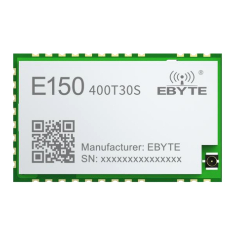
E52-400/900NW22S is a wireless serial port LoRa MESH networking module based on LoRa spread spectrum technology. The
maximum output power is +22 dBm, the maximum air rate can reach 62.5K, and the maximum supported baud rate is 460800 bps. The
operating frequency range of the E52-400NW22S module is 410.125~509.125 MHz (default 433.125 MHz), and the operating
frequency range of the E52-900NW22S module is 850.125~929.125 MHz (default 868.125 MHz).
E52-400/900NW22S adopts the new LoRa MESH networking technology, which has the functions of
decentralization, self-routing, network self-healing, multi-level routing, etc. It is suitable for smart home and industrial
sensors, wireless alarm security systems, building automation solutions, Smart agriculture and other application
scenarios.
E52-400NW22S E52-900NW22S
1.2 Function description
The LoRa MESH network adopts a decentralized structure. The entire network is composed of only two types of
nodes: terminal nodes and routing nodes. There is no need for a central node or coordinator to participate in network
management; users can also build a MESH network using only routing nodes. Routing nodes are similar to terminal
nodes, but terminal nodes do not have routing functions. Terminal nodes are generally deployed at the edge of the
network and are generally used to design low-power nodes, but currently do not support low-power functions. Routing
nodes need to continuously receive data from the network for routing updates and data forwarding, so routing nodes
cannot be used as low-power nodes.
CSMA avoidance technology is adopted in the MESH network. The CSMA avoidance mechanism can prevent
nodes from sending wireless data at the same time as much as possible and reduce the probability of data collision errors.
The routing node will automatically collect information from surrounding nodes to form a multi-hop communication
network; when a link fails or is abnormal, the routing node will re-establish a new path after several consecutive
communication failures.
The network supports four communication methods, Unicast, Multicast, Broadcast and Anycast. Users can choose
different communication methods according to different application scenarios. Among them, unicast and broadcast are
the simplest and most basic communication methods. In unicast mode, routes will be automatically established and
request responses will be returned to determine the data transmission path; in broadcast mode, all routing nodes will start

Chengdu Ebyte Electronic Technology Co.,Ltd.. E52-400/900NW22S User Manual
CopyriCopyright ©2012–2023, Chengdu Ebyte Electronic Technology Co.,Ltd.
2
a data relay after receiving data. The multicast mechanism is relatively complex and can achieve one-to-many
communication. Users need to configure the multicast group address first, similar to a public address. Anycast is usually
used for data exchange between different networks. Data will not be forwarded under anycast. Under anycast, two
communication methods, unicast and broadcast, can be implemented depending on the target address. Users can transmit
any data to any module within the communication range.
During network transmission, data will be encrypted using special algorithms by default to ensure data privacy and
security. In addition, in order to avoid data errors caused by interference from other nodes, multiple verifications are
performed on the data at the network layer to ensure the reliability and accuracy of the transmitted data.
1.3 Function description
LoRa MESH: Using advanced LoRa modulation method, it has the advantage of long-distance anti-interference,
greatly improving the coverage of the entire MESH network;
Super large network capacity: the theoretical number of LoRa MESH network is as high as 65535, and the proposed
network size is about 200;
Decentralization: The entire network is composed of only two types of nodes: terminal nodes and routing nodes,
and there is no need for a central node or coordinator to participate in network management;
Automatic routing: When initiating a data request, each routing node can automatically initiate connections with
surrounding nodes to determine the data transmission path, without the need for the coordinator to participate in
path planning;
Network self-healing: When a link fails, the routing node re-establishes a new path after several communication
attempts fail;
Multi-level routing: Routing nodes can automatically transmit data to lower-level routing, and the automatically
generated routing table controls the transmission direction of data;
Path optimization: Routing information will be continuously and automatically updated and optimized with data
transmission in the network to ensure the stability of the entire network;
Avoidance mechanism: CSMA avoidance mechanism can greatly reduce the possibility of air signal collision;
Communication methods: Supports four communication methods: Unicast, Multicast, Broadcast and Anycast;
E52-400NW22S module frequency range: works in the 410.125 ~ 509.125 MHz frequency band, supports 100
channels, and the channel spacing is 1 MHz;
E52-900NW22S module frequency range: works at 850.125 ~ 929.125 MHz, supports 80 channels, and the channel
interval is 1 MHz;
Multiple verification: ensure the reliability and accuracy of the data transmission process;
High throughput: The entire network is combined in time and space to achieve high concurrency performance;
Remote configuration: Supports remote changes of basic communication parameters of the entire network.
1.4 Network topology
LoRa MESH network supports two types of devices: routing nodes and terminal nodes.
Routing node: Routing node receives data in the network for routing updates and data forwarding.
Terminal node: Terminal nodes do not have routing functions and are generally deployed at the edge of the network.

Chengdu Ebyte Electronic Technology Co.,Ltd.. E52-400/900NW22S User Manual
CopyriCopyright ©2012–2023, Chengdu Ebyte Electronic Technology Co.,Ltd.
3
The network topology of routing nodes and terminal nodes is as shown in the figure:
1.5 Application scenario
Smart home and industrial sensors, etc.
Wireless alarm security system;
Building automation solutions;
Smart agriculture;
Smart logistics and warehousing.

Chengdu Ebyte Electronic Technology Co.,Ltd.. E52-400/900NW22S User Manual
CopyriCopyright ©2012–2023, Chengdu Ebyte Electronic Technology Co.,Ltd.
4
II.Specifications
2.1 Limit parameters
The main parameters
Performance
Remark
Minimum
value
Maximum
value
Voltage
0V
3.6V
≥3.3V can guarantee the output power. If it
exceeds 3.6V, the module may be burned. There
is no LDO inside the module. It is recommended
to connect an external 3.3V LDO.
Operating temperature
-40℃
+85℃
Industrial grade design
Working humidity
10%
90%
-
Storage temperature
-40℃
+125℃
-
2.2 Working parameters
The main parameters
Performance
Remark
Minimu
m value
Typical
value
Maximu
m value
Working voltage (V)
1.8
3.3
3.6
≥3.3V can guarantee the output power. If it
exceeds 3.6V, the module may be burned. There is
no LDO inside the module. It is recommended to
connect an external 3.3V LDO.
Communication level (V)
3.3
It is recommended to add level conversion when
using 5.0V TTL
Working temperature
(℃)
-40
-
+85
Industrial grade design
Working frequency band
(MHz)
410.125
433.125
509.125
E52-400NW22S module working frequency band,
supports ISM frequency band
850.125
868.125
929.125
E52-900NW22S module working frequency band,
supports ISM frequency band
Power
consum
ption
Emission
current (mA)
-
128
-
Instantaneous power consumption
Working
current (mA)
-
14
-
-
Transmit power (dBm)
-9
22
22
User configurable
Over-the-air rate (bps)
7K
62.5K
62.5K
Three air speed levels are available (62.5K,
21.875K, 7K)
Receiving sensitivity
(dBm)
-121
-116
-111
Sensitivity corresponding to three air speeds

Chengdu Ebyte Electronic Technology Co.,Ltd.. E52-400/900NW22S User Manual
CopyriCopyright ©2012–2023, Chengdu Ebyte Electronic Technology Co.,Ltd.
5
The main parameters
Description
Remark
Reference distance
2.5 Km
In a clear and open environment, the antenna gain is 3.5dBi, the
antenna height is 2.5 meters, and the air rate is 7Kbps.
2.0 Km
In a clear and open environment, the antenna gain is 3.5dBi, the
antenna height is 2.5 meters, and the air rate is 21.875Kbps.
1.6 Km
In a clear and open environment, the antenna gain is 3.5dBi, the
antenna height is 2.5 meters, and the air rate is 62.5Kbps.
Subcontracting method
200 Btye
The maximum capacity of a single package. It is prohibited to
exceed the maximum capacity.
Modulation
LoRa
-
Communication Interface
UART serial
port
3.3V TTL level
Packaging method
SMD type
-
Dimensions
20*14mm
±0.1mm
Antenna interface
IPEX/stamp
hole
Characteristic impedance is about 50Ω
Weight
1.2g
±0.1g
III. Mechanical Dimensions and Pin Definition

Chengdu Ebyte Electronic Technology Co.,Ltd.. E52-400/900NW22S User Manual
CopyriCopyright ©2012–2023, Chengdu Ebyte Electronic Technology Co.,Ltd.
6
Pin
number
Pin
name
Pin direction
Pin usage
1
PB3
Input / Output
Some function indication pins, high level by default, active low level
(connected to test suite LED2)
2
PB4
Input / Output
RF transmission indication pin, default high level, active low level
(connected to test suite LED1)
3
PB5
Input / Output
Not used yet, NC recommended
4
PB6
Input / Output
Not used yet, NC recommended
5
PB7
Input / Output
Not used yet, NC recommended
6
PB8
Input / Output
Not used yet, NC recommended
7
PA0
Input / Output
Default is high level, pull it low when power on to enter the Bootloader
(connected to the test suite KEY button)
8
PA1
Input / Output
Not used yet, NC recommended
9
PA2
Input / Output
UART_TXD, serial port transmit pin
10
PA3
Input / Output
UART_RXD, serial port receiving pin
11
PA4
Input / Output
Not used yet, NC recommended
12
PA5
Input / Output
Not used yet, NC recommended
13
GND
Input / Output
Ground wire, connected to the power reference ground
14
ANT
Input / Output
Antenna interface, 50Ω characteristic impedance (connected to SMA
interface of test kit)
15
GND
Input / Output
Ground wire, connected to the power reference ground
16
PA8
Input / Output
Not used yet, NC recommended
17
NRST
Input
Reset pin, default high level, active low level (connected to test suite RST
button)
18
PA9
Input / Output
Not used yet, NC recommended
19
PA12
Input / Output
Not used yet, NC recommended
20
PA11
Input / Output
Not used yet, NC recommended
21
PA10
Input / Output
Not used yet, NC recommended
22
PB12
Input / Output
Not used yet, NC recommended
23
PB2
Input / Output
Not used yet, NC recommended
24
PB0
Input / Output
Not used yet, NC recommended
25
PA15
Input / Output
Not used yet, NC recommended
26
PC13
Input / Output
Not used yet, NC recommended
27
GND
Input / Output
Ground wire, connected to the power reference ground
28
VDD
Input
Power supply VDD, the maximum input voltage is 3.6V, it is recommended
to supply power through 3.3V LDO
29
SWDIO
-
Debug pin
30
SWCLK
-
Debug pin

Chengdu Ebyte Electronic Technology Co.,Ltd.. E52-400/900NW22S User Manual
CopyriCopyright ©2012–2023, Chengdu Ebyte Electronic Technology Co.,Ltd.
7
IV. Recommended Connection Diagram
Serial
number
Brief connection instructions between the module and the microcontroller (the above figure takes
the STM8L microcontroller as an example)
1
The wireless serial port module is TTL level, please connect it to a 3.3V TTL level MCU.
2
When using a 5V microcontroller, please perform UART level conversion.
3
TVS protection and capacitors need to be added to the outside of the power supply (it is recommended to
add a 22uF low ESR electrolytic capacitor or tantalum capacitor).
4
The RF module is sensitive to pulse static electricity. Please do not hot-swap the module.
5
There is no LDO inside the module. It is recommended to connect an external 3.3V LDO for power
supply.

Chengdu Ebyte Electronic Technology Co.,Ltd.. E52-400/900NW22S User Manual
CopyriCopyright ©2012–2023, Chengdu Ebyte Electronic Technology Co.,Ltd.
8
V. Test Suite
5.1 Test Suite Introduction
Figure 5.1.1 Physical Object
The E52-400/900NW22S-TB test kit is designed to help users quickly evaluate module-related functions. For
first-time use, it is recommended to purchase several test kits directly for testing (the test kit has been soldered with
the E52-400/900NW22S module).
The hardware integrates power supply circuit, reset circuit, button circuit, power indicator light PWR, work
indicator LED, etc., and an 18650 battery box is reserved at the bottom. Customers can install 18650 batteries by
themselves for testing.
The test kit has connected the required pins of the module to the corresponding peripherals, the most important of
which is the TTL to USB circuit. Users only need to connect the Micro USB to the computer, and a COM port will
appear on the computer's device manager.
If you do not see the corresponding COM, there may be the following possibilities:
The CH340 driver is being installed automatically, please wait patiently for a while; if the driver cannot be
installed automatically, you need to install it manually.
Check whether the module power light PWR is on and whether the module is supplying power normally?
Figure 5.1.2 Device Manager checks COM port
Download any serial port debugging tool. Under the relevant downloads on the official website, there is the XCOM
serial port debugging assistant;
Open the serial port debugging assistant, follow the above steps to simply set up the software, and send

Chengdu Ebyte Electronic Technology Co.,Ltd.. E52-400/900NW22S User Manual
CopyriCopyright ©2012–2023, Chengdu Ebyte Electronic Technology Co.,Ltd.
10
VI. Command Introduction
6.1 Introduction to AT commands
AT instructions are divided into three categories: command instructions, setting instructions and query instructions;
AT command uses 115200 bps baud rate by default, without sending new lines;
Different AT commands require different numbers of input parameters. Different parameters need to be separated by
",". The input parameters are uniformly decimal values. You need to read the instruction set carefully for details. If
the number of input parameters of the AT command is wrong, the serial port will Returns data similar to
"AT+DST_ADDR=CMD_ERR".
Some AT command parameters will be restricted. If the AT command input value is wrong, the serial port will return
data similar to "AT+DST_ADDR=CMD_VALUE_ERR";
If the parameter setting is successful, the serial port will return data similar to "AT+DST_ADDR=OK";
Data in non-AT command sets will be considered transparent data, and the module will initiate a data request, so
you should try to avoid sending data starting with "AT+";
After using the saved instructions, all parameters inside the current module will be saved. Most of the setting
instructions will be saved directly to Flash. Only some common setting instructions can be saved to Flash according
to the parameters.
6.2 Command instruction set
The command instruction has no suffix, and only requires "AT+RESET" to restart the module.
6.3 Query instruction set
The suffix of the query command is "=?". For example, the query module related information command
"AT+INFO=?", the module will return the main parameters of the module.
Command
Instruction
Function
Description
AT+IAP
Enter IAP upgrade mode
After returning AT+IAP=OK, the module immediately restarts
and enters the IAP upgrade mode. It remains powered on for
about 30 seconds and automatically exits the IAP upgrade mode.
AT+RESET
Module restart
After returning AT+RESET=OK, the module will restart
immediately.
AT+DEFAULT
Restore module to factory
settings
After returning AT+DAFAULT=OK, the parameters will be
restored to factory values, and then restart immediately.

Chengdu Ebyte Electronic Technology Co.,Ltd.. E52-400/900NW22S User Manual
CopyriCopyright ©2012–2023, Chengdu Ebyte Electronic Technology Co.,Ltd.
11
Query command
Function
Description
AT+INFO=?
Query the main parameters
of the module
Important command, returns the main parameters of
the module (displayed and used by the serial port
assistant)
AT+DEVTYPE=?
Query module module
model
Return the device model such as E52-400NW22S
AT+FWCODE=?
Query module firmware
code
Return the firmware code such as 7460-0-10
AT+POWER=?
Query module transmit
power
Returns RF output power
AT+CHANNEL=?
Query module working
channel
Return to RF working channel
AT+UART=?
Query module serial port
parameters
Returns the serial port baud rate and check digit
AT+RATE=?
Query module air rate
Return module air rate
[0:62.5K 1:21.825K 2:7K]
AT+OPTION=?
Query module
communication method
Important command, return module communication
method
AT+PANID=?
Query network
identification code
Return network identifier
AT+TYPE=?
Query the node type of the
module
Return module type (routing node/terminal node)
AT+SRC_ADDR=?
Query the address of the
current module
Important instruction, returns the address of the
current module
AT+DST_ADDR=?
Query the address of the
target module
Important instruction, returns the address of the target
module
AT+SRC_PORT=?
Query the port of the
current module
Returns the port of the current module
AT+DST_PORT=?
Query the port of the target
module
Returns the port of the target module
AT+MEMBER_RAD=?
Query multicast member
radius
Returns the propagation radius of multicast members.
The larger the radius, the greater the coverage.
AT+NONMEMBER_RAD=?
Query multicast
non-member radius
Returns the multicast non-member propagation radius.
The larger the radius, the greater the coverage.
AT+CSMA_RNG=?
Query CSMA random
avoidance time
Returns the maximum random avoidance time
AT+ROUTER_SCORE=?
Maximum number of
consecutive route query
failures
Returns the maximum number of consecutive failures.
If this number is exceeded, routing information will be
removed.

Chengdu Ebyte Electronic Technology Co.,Ltd.. E52-400/900NW22S User Manual
CopyriCopyright ©2012–2023, Chengdu Ebyte Electronic Technology Co.,Ltd.
12
6.4 Setting up the instruction set
Set the command suffix to "=%d,%d,%d", for example, set the module target address command
"AT+DST_ADDR=25640,0", the first parameter is the target address, and the second parameter is whether to save
to Flash , the middle needs to be separated by ",".
If there is no <save> parameter in the setting command, it will be saved in Flash.
AT+HEAD=?
Query whether the extra
frame header function is
enabled
Returns whether the extra frame header function is
enabled
AT+SECURITY=?
Query whether the data
encryption function is
enabled
Returns whether the data encryption function is
enabled
AT+RESET_AUX=?
Query whether LED2
changes during automatic
reset
Returns whether LED2 changes to turn on when the
radio frequency is restarted.
AT+RESET_TIME=?
Query the automatic reset
time
Returns the radio frequency automatic restart time,
unit min
AT+FILTER_TIME=?
Query broadcast filter
timeout
Returns the broadcast filter timeout
AT+ACK_TIME=?
Query request response
timeout
Return request response timeout
AT+ROUTER_TIME=?
Query routing request
timeout
Returns the routing request timeout
AT+GROUP_ADD=?
Query GROUP
information
Return multicast group address table
AT+GROUP_DEL=?
AT+GROUP_CLR=?
AT+ROUTER_CLR=?
Query routing table
information
Return routing table information
AT+ROUTER_SAVE=?
AT+ROUTER_READ=?
AT+MAC=?
Query MAC unique
address
Returns the MCU's unique 32-bit MAC address
AT+KEY=?
Query encryption key
Unable to read to avoid key leakage

Chengdu Ebyte Electronic Technology Co.,Ltd.. E52-400/900NW22S User Manual
CopyriCopyright ©2012–2023, Chengdu Ebyte Electronic Technology Co.,Ltd.
13
Setup instructions
Function
Description
AT+INFO=0
Query module advanced
parameters
Return to the module for more advanced
setting parameters (displayed using the
serial port assistant)
AT+POWER=<power>,<save>
Set module transmit
power
<power>: RF output power (-9 ~ +22 dBm)
<save>: whether to save to Flash
AT+CHANNEL=<channel>,<save>
Set module working
channel
<channel>:
E52-400NW22S frequency band: RF
working channel (0 ~ 99)
E52-900NW22S frequency band: RF
working channel (0 ~ 79)
<save>: whether to save to Flash
AT+UART=<baud>,<parity>
Set module serial port
parameters
Restart takes effect
<baud>: serial port baud rate (1200 ~
460800)
<parity>: Check digit (8N1 8E1 8O1)
AT+RATE=<rate>
Set module air rate
<rate>:0:62.5K 1:21.825K 2:7K
AT+OPTION=<option>,<save>
Set module
communication method
Commonly used instructions, generally
broadcast and unicast
<option>: Communication method (1 ~ 4)
<save>: whether to save to Flash
AT+PANID=<panid>,<save>
Set network ID
Commonly used instructions, it is not
recommended to use the default value
<panid>: network identification code (0 ~
65535)
<save>: whether to save to Flash
AT+TYPE=<type>
Set the node type of the
module
<type>: 0: routing node 1: terminal node
AT+SRC_ADDR=<addr>,<save>
Set the address of the
current module
(Guaranteed uniqueness)
Commonly used commands, the default is
the last 15 digits of the MAC address
<addr>: current address (0 ~ 65535)
<save>: whether to save to Flash
AT+DST_ADDR=<addr>,<save>
Set the address of the
target module
Commonly used instructions to set the target
address
<addr>: target address (0 ~ 65535)
<save>: whether to save to Flash
AT+SRC_PORT=<port>,<save>
Set the port of the current
module
<port>: Default current port 1
<save>: whether to save to Flash
AT+DST_PORT=<port>,<save>
Set the port of the current
module
<port>: Default target port 1
<save>: whether to save to Flash

Chengdu Ebyte Electronic Technology Co.,Ltd.. E52-400/900NW22S User Manual
CopyriCopyright ©2012–2023, Chengdu Ebyte Electronic Technology Co.,Ltd.
14
AT+MEMBER_RAD=<rad>,<save>
Set module multicast
member radius
For multicast use, it is recommended to
keep the default
<rad>: multicast member radius (0 ~ 15)
<save>: whether to save to Flash
AT+NONMEMBER_RAD=<rad>,<save>
Set module multicast
non-member radius
For multicast use, it is recommended to
keep the default
<rad>: Multicast non-member radius (0 ~
15)
<save>: whether to save to Flas
AT+CSMA_RNG=<rng>
Set CSMA random
avoidance time
it is recommended to keep the default
Random avoidance time range (20 ~ 65535)
ms
AT+ROUTER_SCORE=<score>
Set the maximum
number of consecutive
routing failures
<score>: The maximum number of
consecutive route failures,
Routes need to be re-established after
exceeding
AT+HEAD=<enable>
Set the extra frame
header function enable
switch
<enable>: Whether the extra frame header
function is enabled
AT+SECURITY=<enable>
Set the data encryption
function enable switch
<enable>: Whether the data encryption
function is enabled
AT+RESET_AUX=<enable>
Set auto-reset LED2
change switch
<enable>: Automatic reset LED2 change
enable
AT+RESET_TIME=<reset_time>
Set automatic reset time
<reset_time>: automatic reset interval time
(min)
AT+FILTER_TIME=<time>
Set broadcast filter
timeout
it is recommended to keep the default
<time>: Broadcast filter timeout (3000 ~
65535 ms)
AT+ACK_TIME=<time>
Set request response
timeout
it is recommended to keep the default
<time>: Request response timeout (1000 ~
65535 ms)
AT+ROUTER_TIME=<time>
Set routing request
timeout
it is recommended to keep the default
<time>: Routing request timeout (1000 ~
65535 ms)
AT+GROUP_ADD=<gruop>
Add GROUP
information
<group>: Add multicast group address, up
to 8 can be added
AT+GROUP_DEL=<gruop>
Delete GROUP
information
<group>: Delete multicast group address
AT+GROUP_CLR=<enable>
Delete GROUP
information table
<enable>: 1: Delete the entire GROUP
information table
AT+ROUTER_CLR=<enable>
Clear routing table
information
<enable>: 1: Delete the entire routing
information table

Chengdu Ebyte Electronic Technology Co.,Ltd.. E52-400/900NW22S User Manual
CopyriCopyright ©2012–2023, Chengdu Ebyte Electronic Technology Co.,Ltd.
15
6.5 Parameter value table
AT+ROUTER_SAVE=<enable>
Flash operation of
routing table
<enable>: 1: Save routing information table
to Flash
<enable>: 0: Delete the routing information
in Flash
AT+ROUTER_READ=<enable>
Read routing information
in Flash
<enable>: 1: Load the routing information
table in Flash
AT+KEY=<key>
Set data encryption key
Communication is impossible if the keys are
different
<key>: Data encryption key [0~0x7FFF
FFFF]
Parameter
name
Value range
Function
Description
<save>
[0~1]
Whether parameters are saved to
Flash
[1: Save, 0: Do not save]
<power>
[-9~22]
Set module transmit power
RF output power [-9~+22] dBm
<channel>
[0~99]
Set the working channel of the
E52-400NW22S module
Working channel [0~99],
Corresponding frequency 410.125 ~ 509.125
MHz
Operating frequency = 410.125 + channel * 1
MHz
[0~79]
Set the working channel of the
E52-900NW22S module
Working channel [0~79],
Corresponding frequency 850.125 ~ 929.125
MHz
Operating frequency = 850.125 + channel * 1
MHz
<baud>
See
description
Set baud rate
It will take effect after restarting, and the
following baud rates are supported:
1200,2400,4800,9600,19200,38400,
57600,115200,230400,460800 bps
<parity>
[0~2]
Set check digit
Serial port check digit
[0:8N0 1:8E1 2:8O1]
<rate>
[0~3]
Set air rate
[0:62.5K 1:21.825K 2:7K]
<option>
[1~4]
Set communication method
Communication method
[1: Unicast 2: Multicast 3: Broadcast 4:
Anycast]
<panid>
[0~65534]
Set network ID
Network identification code
[0x0000~0xFFFE]

Chengdu Ebyte Electronic Technology Co.,Ltd.. E52-400/900NW22S User Manual
CopyriCopyright ©2012–2023, Chengdu Ebyte Electronic Technology Co.,Ltd.
16
6.6 Parameter Notes
If the setting command does not have the save option <save> parameter, it will be saved in Flash.
After the baud rate <baud> and parity bit <parity> are set, a reboot is required to take effect. You can use
"AT+RESET" to reset.
Address <addr> and network identification code <panid> are generally not recommended to be set to 0xFFFF.
0xFFFF is used as a broadcast address and broadcast network.
Node type <type> will change the highest bit of the local address. Generally, you need to set the node type <type>
after setting the local address <addr>.
<type>
[0~1]
Set the node type of the module
[0: Routing node 1: Terminal node]
<addr>
[0~65534]
Set module address
Address range [0x0000~0xFFFE]
Routing node: 0x0000~0x7FFF
Terminal node: 0x8000~0xFFFE
<group>
[0~65534]
Set multicast group address
Group address range [0x0000~0xFFFE]
<port>
[1、14]
Port settings
Different ports correspond to different
functions, and the remaining ports have no
functions yet.
Port 1: Output data directly through UART
Port 14: Parse data as AT commands
<rad>
[0~15]
Set the propagation radius under
multicast
Multicast propagation radius[0~15]
The larger the radius, the greater the number
of propagation stages.
<rng>
[20~65535]
Set CSMA random avoidance
time
Random avoidance time [20~65535] ms
<score>
[1~15]
Set the maximum number of
consecutive failures,Exceeding
this will require re-initiating the
routing request
Maximum number of consecutive failures
[1~15]
<enable>
[0~1]
Various function switches
[1: Function enabled 0: Function disabled]
<reset_time>
[0~255]
Automatic reset RF time
Automatic reset time [1~255] min
[0: Turn off automatic reset]
<time>
See
description
Network timeout
Broadcast filter timeout [3000~65535] ms
Request response timeout [1000~65535] ms
Routing request timeout [1000~65535] ms
<key>
[0~0x7FFF
FFFF]
Network encryption key
Encryption key [0~0x7FFF FFFF]
Table of contents
Other Ebyte Control Unit manuals

Ebyte
Ebyte E18 Series User manual

Ebyte
Ebyte E79-400DM2005S User manual

Ebyte
Ebyte E22-400T30D User manual

Ebyte
Ebyte E32-DTU-V8 User manual

Ebyte
Ebyte E104-BT09 User manual

Ebyte
Ebyte E150-400T30S User manual

Ebyte
Ebyte E31-433T17S User manual

Ebyte
Ebyte ESP32-WROVER-IE User manual

Ebyte
Ebyte E79-900DM2005S User manual

Ebyte
Ebyte E-840-TTL-4G02 User manual

Ebyte
Ebyte E30-490T20S User manual

Ebyte
Ebyte E31-433T30D User manual

Ebyte
Ebyte E73 2G4M04S1B User manual

Ebyte
Ebyte E34-2G4H27D User manual

Ebyte
Ebyte E104-BT11 User manual

Ebyte
Ebyte E30-TTL-100 User manual

Ebyte
Ebyte E22-400M22S User manual

Ebyte
Ebyte E70 Series User manual

Ebyte
Ebyte AM22-12W2405V User manual

Ebyte
Ebyte E21-400G37S User manual