wirsbo DuoMix 201 User manual

OUTDOOR RESET
In order to maintain occupant comfort with a hot water heating system, the
heat supplied to the building must equal the heat lost by the building.
• The heat supplied to a building is proportional to the temperature of the
water and the surface of the heating area. A small surface area such as
baseboard radiators requires a higher water temperature than a larger
surface area such as radiant floors.
• The heat supplied to a building/space can be changed by increasing or
decreasing the supply water temperature. As the outdoor temperature
falls the supply water temperature rises.
Control Strategy
TheWIRSBODuoMix201providescontroloftwovariablespeedinjectionmixingdevicesinordertosatisfyatwotemperaturesystem.
Thesystemmayconsistofatwotemperatureradiantfloorheatingapplication,oracombinationofsnowmeltingandradiantfloorheating.
The control is designed for use with radiant systems but can be easily integrated to other hydronic applications (baseboard, fan coil).
The control is capable of providing boiler return protection in order to prevent boiler flue gas condensation.
The DuoMix 201 includes a large Liquid Crystal Display (LCD) which provides temperature read-out and adjustable settings.
ForbuildingspaceheatingapplicationsthecontrolincludesfeaturessuchasWarmWeatherShutDown(WWSD),outdoorreset,pump
exercising,andmaximumsupplytemperatureadjustment.Inthesnowmeltingmodethecontrolprotectstheslabagainstthermalshock,
has idling capabilities, Warm Weather Shut Down (WWSD), and Cold Weather Cut Off (CWCO).
Constant
Room Temperature
Outdoor
Temperature
Drop
Heat
Loss
Increase
A3030005
DuoMix 201
Installation Instructions
-10
(-23)
70
(21) °F
(°C)
70
(21)
150
(65)
50
(10) 30
(-1) 10
(-12)
90
(32)
110
(43)
130
(54)
Design
Outdoor
Temp.
Design
Room
Temp.
Outdoor Air Temperature
90
(32)
Supply Water Temperature
Design
Supply
Temp.
WWSD
60 (15.5)
Theory
The calculated heat loss of a building or space is based on the coldest weather conditions the
area experiences over the heating season. If the heat demand is analyzed as a percentage of
the heating systems capacity, the heating system operates at or near maximum capacity for
asmallportionoftheheatingseason.Ifthewatertemperatureiscontrolledusinganon-weather
responsivetemperingdevice,shownasthedottedline,thelineisflatanddoesnotflucuatewith
the demand for heat. Resetting the supply water temperature (solid line) allows for the supply
water temperature to adjust itself to the demands on the heating system. Lowering the supply
watertemperatureinwarmertimesoftheheatingseasonwillallowtheradiantzonestobeopen
and run longer, providing increased comfort and efficiency.
WaterTemperatureOptimization
The Wirsbo DuoMix 201 uses actual data to program the control on start-up, eliminating the
unknowns. Until now, resetting the supply water temperature to a radiant panel meant using
terminology such as "curves" and "shifts". The DuoMix now eliminates manually selecting the
proper curve based on the design data. From the user inputted data, the control creates a
relationship(orratio) between theoutdoortemperatureand the water temperaturesuppliedto
the radiant application. The control automatically adjusts the supply water temperature for
every1°Fdropinoutdoortemperature.Inordertocorrectlyresetthesupplywatertemperature,
a few parameters are required:
OutdoorDesignTemperature
TheOutdoorDesignTemperatureisusedtocalculatetheheatloadrequiredatthemostsevere
weather conditions expected during a normal heating season.
Design Supply Water Temperature
The Design Supply Water Temperature is the temperature of water supplied to the radiant
panel(s)tomeettherequirementsoftheheatloadcalculatedattheoutdoordesigntermperature.
Design Room Temperature
TheDesignRoomTemperatureistheindoorairtemperatureusedintheheatlosscalculations.
Warm Weather Shut Down (WWSD)
When the outdoor air temperature is warmer than the Warm Weather Shut Down setting, no
additionalheatissuppliedtothebuilding;therefore,theheatingsystemcanbeshutdown.The
WWSD setting has no effect on the heating curve slope.

DuoMix Installation Handbook
2
Indoor Temperature Feedback
Most buildings have internal heat gains due to people, passive solar heating and mechanical
or electrical equipment. If only the outdoor temperature is measured, the control cannot
compensate for these internal heat gains and the building may overheat. In order to prevent
overheating, indoor temperature feedback can be combined with the outdoor reset strategy.
From this indoor temperature feedback, the control can match the supply water temperature
to the heat loss of the building. If the indoor temperature is too warm, the control reduces the
supply water temperature, and if the indoor temperature is too cold, the control increases the
supply water temperature.
SETPOINT OPERATION
Some loads, such as pool heating and floor warming, require a low fixed setpoint supply temperature. These loads should be regulated
through a mixing device.
MIXING OPERATION
Thefullrangeofwatertemperaturesrequiredthroughaheatingseasoncan
be provided with a standard (non-condensing) boiler by incorporating a
modulatingmixingdeviceintothe system. Variable speed injection pumps
can modulate both the system supply water temperature and the boiler
return water temperature. The full modulation of water temperatures
improves comfort in the building and also protects the boiler from cool
return water.
Boiler Protection
Cool water is often returned to the boiler from snow melting or low temperature radiant floor heating systems.
This cool boiler return water may cause the boiler to operate at such a low temperature that the flue gases
condense. Alternatively, when the boiler surfaces are hot due to previous loads such as domestic hot water
generation, the large temperature difference (∆T) between the boiler and its return water can cause the boiler
to become thermally shocked. Proper protection of the boiler under these circumstances requires modulating
mixing devices that can temporarily reduce the heating load. This is accomplished by reducing the speed of
injection pumps.
System Maximum Supply
Hydronicradiantfloorheatingsystems,usuallyoperateatwatertemperaturesthatarebelowtheminimumboiler
return temperature. This is due to the large surface area of the floors which radiate a significant amount of heat
atlowwatertemperatures.Floorheatingsystemsalsohaveamaximumsupplywatertemperaturelimittoprotect
the application in which it is installed. In such systems a mixing device is required to control and limit the supply
water temperature to the radiant panel.
Sequence of Operation
POWERING UP THE CONTROL
When the WIRSBO DuoMix 201 is powered up, the words "WIRSBO 201" are displayed for
4 seconds. The control then displays the outdoor temperature and begins normal operation.
WARM WEATHER SHUT DOWN (WWSD)
When the outdoor temperature rises above the WWSD 1 or WWSD 2 settings, the control
shutsofftherespectivemixingsystempumpandvariablespeedinjectionpump.The
WWSD
element is displayed whenever both mixing loops are in WWSD. If no heat is required in any
mixing system, the boiler enable relay is also turned off.
MIXING OPERATION
The WIRSBO DuoMix 201 controls the supply water temperature to two
different mixing loops (mixing 1 and mixing 2). The control provides the
differentwatertemperaturesthroughtwoseparatevariablespeedinjection
pump systems. The mixing 1 section can be chosen to operate in setpoint
oroutdoorresetmode.An optional indoor sensor may be installed in order
toobtainindoortemperaturefeedback.Themixing2sectioncanbechosen
to operate in setpoint, outdoor reset, or snow melting mode.
Outdoor Reset Operation
The DuoMix 201 can be used to provide outdoor reset to the mixing loops.
The outdoor reset mode (
RST
) of operation on mixing 1 or mixing 2 must
be selected through the display interface.

DuoMix Installation Handbook
3
Wirsbo 201
tekmar
Zone Control
°F
SB 2 3 4 SB 2 3 4 SB 2 3 4
R1 R2 Y1 Y2 R1 R2 Y1 Y2 R1 R2 Y1 Y2
C
R
S
ES
ES
C
R
S
ES
ES
Wirsbo Zone Control Module
Duo
Mix
External Mixing Demand
When24 or 120 V (ac)is applied to the
Mix1Demand
terminals, the control
turns on mixing pump 1 (
Mix1 Pmp
) and operates the variable speed
injection pump 1 (
Var1 Pmp
). If 24 or 120 V (ac) is applied to the
Mix2
Demand
terminals, the control turns on mixing pump 2 (
Mix2 Pmp
) and
operates the variable speed injection pump 2 (
Var2 Pmp
). The external
demands may be obtained from the WIRSBO zone control, zone valve
endswitches, or relay contacts.
Indoor Sensor
Anindoorsensormaybeconnectedtoamixingsectioninordertoobtainindoortemperaturefeedback.The
SENSOR1
or
2
settingmust
be set to
INDR
through the display interface. An external mixing demand is still required in order to provide heat.
tekmar Zone Control
Outdoor reset can be combined with zoning. Through Room Temperature Units (RTU), a
tekmar Zone Control can provide indoor temperature feedback to the WIRSBO 201 control.
The201willthenadjustthesupplywatertemperaturetosatisfythezonewiththehighestwater
temperature requirement. Heat to the remaining zones will be cycled on and off by the zone
controlusingzonevalves or pumps. If a tekmarZoneControlisconnectedtoeither the mixing
1 and/or mixing 2 sections, an external demand is not required, although it is still operational
for additional zones that are controlled by thermostats.
Boiler Enable
WhenheatisrequiredintheheatingsystemtheWIRSBODuoMix201turns
on the
Boiler Enable
relay. Once the
Boiler Enable
relay is turned on, a
minimum of 3 minutes is allowed before turning the relay back off if the
supply water temperatures are satisfied and the injection pumps have
ramped down to 0%. If the heat demand is removed, the boiler is immedi-
ately turned off.
BoilerProtection
A boiler sensor must be installed on the return line to the boiler in order to
obtain boiler protection against flue gas condensation, if required. If the
boilerreturnwatertemperatureapproachestheboilerminimumsetting(
Boil
RET
), the control maintains the
Boiler Enable
relay on and reduces the
speed of the injection pump 2. If the boiler temperature still does not
increase, then the speed of injection pump 1, will be decreased.
System Maximum Supply
The WIRSBO DuoMix 201 has a maximum supply setting (
MAX SUP 1
and
MAX SUP 2
) for
each mixing loop, which sets an upper operating limit to the mixed supply water temperatures
fortheapplicationinwhichthetubingisinstalled.ThisvalueisdifferentthantheDesignSupply
Setting (
DSN SUP1
and
DSN SUP2
).
SETPOINT OPERATION
The WIRSBO DuoMix 201 can be used to provide one or two fixed water temperatures to the
mixingloops.Thesetpoint(
SETP
)modeofoperationonmixing1ormixing2mustbeselected
throughthe display interface. When 24 or 120V(ac) is applied to the
Mix1Demand
terminals,
the control turns on the mixing pump 1 (
Mix1 Pmp
) and operates the variable speed injection
pump 1 (
Var1 Pmp
) in order to supply the adjusted
SETPNT 1
water temperature. The mixing
2 section operates in the same manner.
SNOW MELTING OPERATION
The mixing 2 section on the DuoMix 201 may be used to control a snow
melting system. The snow melting mode of operation must be selected
throughthedisplayinterface(
SNOW
).Whenthe
Start
buttonispressedand
held for 1 second on the control or on the Remote Module Unit 040, the
control enters the snow melting mode of operation and displays the
RUN
TIME
. The
RUN TIME
can now be adjusted for the desired operating time.
Thesnowmeltingcanalso be enabled by the Remote Snowmelt Enable Kit
A3040039. At any time during the snow melting session, the melting time
remainingmaybeviewed.(SeeViewMenu).An external
Mix2Demand
for
4secondsisequivalenttopressingthe
Start
button.IftheSnowmeltEnable
Kit is not desired, a Slab Sensor A3060072 and a Universal Sensor
A3060071 are required for snow melt operation.

DuoMix Installation Handbook
4
View
Mix 1 Demand
Mix 2 Demand
Minimum
Maximum
Melting
Idling
CWCO
°F
Slab Supply
Sensor
Slab Return
Sensor
Slab Sensor
°F
View
2
%
2
Mix 1 Demand
Mix 2 Demand
Minimum
Maximum
Melting
Idling
CWCO
°F
View
2
%
2
Mix 1 Demand
Mix 2 Demand
Minimum
Maximum
Melting
Idling
CWCO
Melting mode
Once in melting mode, the DuoMix 201 maintains the slab at the programmed
MELTING
temperaturebycontrollingthespeedofthe injectionpump2(
Var2Pmp
).Wheneverthecontrol
is in the melting mode, the mixing pump (
Mix2 Pmp
) is turned on and the
Melting
pointer is
displayed.
Idling mode
When the melting system starts off from a cold temperature, the time required for the slab to
reach the melting temperature can be excessive. To decrease this start up time, the slab can
bemaintainedatanidlingtemperatureuntilmeltingisrequired.Theidlingfeatureisalsouseful
for preventing frost and light ice formation. When the control is in idling mode, the slab is
maintained at the IDLING temperature and the
Idling
pointer is turned on.
Warm Weather Cut Off (WWCO)
If the slab and outdoor temperatures rise above the
MELTING
temperature, heating the slab is no longer required. The control therefore
shuts down the melting system. When the outdoor or slab temperature drops below the
MELTING
temperature, the control exits
WWCO
and continues with normal operation.
Cold Weather Cut Off (CWCO)
Maintaining the slab at a
MELTING
or
IDLING
temperature in extremely cold weather can be
expensive and may even be impossible. The control therefore turns the melting system off
whentheoutdoortemperaturedropsbelowthe
CWCO
settingandturnsonthe
CWCO
pointer.
If the slab is at the desired
MELTING
temperature, the control will not enter the
CWCO
mode.
Ifthe an enable signal is givenduring the
CWCO
mode, the control continues to meltonce out
of the
CWCO
mode.
Slab Protection
To protect the slab from cracking due to thermal stresses, the control limits the rate of heat
applied to the slab through a
∆
T MAX
setting. The ∆T represents the difference between the
measuredslabsupplyandreturnfluidtemperatures.Ifthistemperaturedifferenceapproaches
the
∆
T MAX
setting, the control operates the variable speed injection pump 2 to maintain the
∆Tatthe
∆
TMAX
setting.The
Maximum
pointer isturnedonwhenthetarget∆Tisgreaterthan
the
∆
T MAX
setting.
Ramping the ∆T during Melting System Start Up
When the control is in melting mode, the control maintains the maximum ∆T and slowly
increases the slab temperature to prevent thermal shock of the slab.
Run Time
Priortothecontrolenteringthesnowmeltingmode,a
RUNTIME
shouldbeselected.Thesnowmeltingtimewillstartcountingdownonce
theslabisup tomeltingtemperature.Ifthe
Start
buttononthe controlortheRemoteDisplay 040ispressedwhilesnow meltingisenabled
and the slab is up to temperature, the run time counter is reset. Pressing the stop button on either control will end the snow melting
operation.UsingtheSnowMeltingEnableKitA3040039, pressingthe buttonduringwarmuporruntimewillendthesnowmeltoperation.
EXERCISING OF THE PUMPS
To prevent the pumps from seizing after long inactive periods, all pumps are turned on after every 3 days of no
operation.The
Mix1Pmp
and
Mix2Pmp
pumprelaysareturnedonfor20secondsandthevariablespeedpump
outputsarerampedupto100%speed.Duringexercising,theLCDscreenflashes"EXERCISE"andthe
Test
LED
flashes. Exercising can be stopped by pressing the
Test
button.
REMOTE DISPLAY A3040040 (tN2). AVAILABLE OCTOBER 1998
ARemoteDisplay A3040040 can beusedtoduplicatethe control display inaremotelocation.
All settings can be remotely adjusted.
SNOW MELT ENABLE KIT A3040039 (tN2)
The Snow Melt Enable Kit is used for snow melting applications. The kit includes a Remote
Start/Stop Module, Mixing 2 Return Sensor A3040071, and a Slab Sensor A3040072. When
a Remote Start/Stop Module is connected to the 201, the LED (Light Emitting Diode) flashes
green or red. When the button is pressed, the control enters the snow melting mode. During
slab warm up, the LED flashes green. Once the slab is up to temperature, the LED remains
green continuously. If an error occurs in the control, the LED flashes red.
Installation
Slab Sensor 072
Universal Sensor 071
A3040071
A3040072
A3040040
ItemMenu
°F
View
!
WWSD
1
%%
2

DuoMix Installation Handbook
5
Caution
Improper installation and operation of this control could result in damage to the equipment and possibly even personal injury.
It is your responsibility to ensure that this control is safely installed according to all applicable codes and standards. This
electroniccontrolisnotintendedforuseasa primarylimit control.Other controlsthat areintended andcertified assafetylimits
must be placed into the control circuit.
STEP ONE GETTING READY
Checkthecontentsofthispackage.Ifanyofthecontentslistedaremissingordamaged,pleasecontactyourwholesalerorWirsbosales
representative for assistance.
Type 201 includes:
• One Wirsbo DuoMix 201 (A3030005)
• Three Universal Sensors (A3060071)
• One Outdoor Sensor (A3060070)
Note Carefullyread theSequenceofOperationsections inallapplicablebrochures toensurethatyouhavechosenthepropercontrol for
your application.
STEP TWO MOUNTING THE CONTROL AND SENSORS
Installing the Control
• Remove the control from its base by pressing down on the release clip in the wiring chamber and sliding the control upwards.
• Mount the base directly onto the wall, DIN rail or an electrical box.
Installing the Outdoor Sensor A3060070
• Remove the screw and pull the front cover off the sensor enclosure.
• The A3060070 can either be mounted directly onto a wall or a 2" x 4" electrical box. When the A3060070 is wall mounted,
the wiring should enter through the back or bottom of the enclosure. Do not mount the A3060070 with the conduit knockout facing
upwards as rain could enter the enclosure and damage the sensor.
• The A3060070 should be mounted on a wall which best represents the heat load on the building (a northern wall for most buildings
and a southern facing wall for buildings with large south facing glass areas). The A3060070 should not be exposed to heat sources
such as ventilation or window openings.
• In order to prevent heat that is transmitted through the wall from affecting the sensor reading, it may be necessary to install an
insulating barrier behind the enclosure.
• The A3060070 should be installed at an elevation above the ground that will prevent accidental damage or tampering.
Installing the Universal Sensor A3060071
•Thesensorcanbestrappeddirectlytothepipeusingthecabletieprovided.Insulationshouldbeplacedaroundthesensortoreduce
the effect of air currents on the sensor measurement.
• The Universal Sensor A3060071 should be placed downstream of a pump or after an elbow or similar fitting. This is especially
importantiflargediameter pipesareusedasthe thermalstratificationwithinthepipe canresultinerroneoussensorreadings.Proper
sensor location requires that the fluid is thoroughly mixed within the pipe before it reaches the sensor.
STEP THREE ROUGH-IN WIRING
Allelectricalwiringterminatesinthecontrolbasewiringchamber.Thebasehasstandard7/8"(22mm)knockoutswhichacceptcommon
wiringhardwareandconduitfittings.Beforeremovingtheknockouts,checkthewiringdiagramandplantheroutingofwires.Thecontrol
base can be installed on a 4-3/4” x 4-3/4” electrical (dryer or range) box to simplify line voltage wiring.
Power must not be applied to any of the wires during the rough-in wiring stage.
• Install the Outdoor Sensor , Boiler Return Sensor, and the two Supply Sensors and run the wiring back to the control.
• If a 10K Indoor Sensor is used, install the Indoor Sensor(s) according to the installation instructions supplied with the sensor and
run the wiring back to the control.
• If a tekmar Zone Control is used, run two wires from the Zone Control to the 201.
• If a Snow Melt Enable Kit A3040039 or a Remote Display Module 040 is used, run two wires from the unit to the 201.
• Run wiring from the other system components (pumps, mix demands, boiler, etc.) to the control. Multi-strand 16 AWG wire is
recommended for all 120 V (ac) wiring due to its superior flexibility and ease of installation into the terminals.

DuoMix Installation Handbook
6
Mix1
Pmp
8
N
56
Var2
Pmp
910 12
N
11 13
NL
Var1
Pmp
14 16
15
N
Mix2
Pmp
Boiler
Enable
7
NPower
Mix1
Pmp
8
N
56
Var2
Pmp
910 12
N
11 13
NL
Var1
Pmp
14 16
15
N
Mix2
Pmp
Boiler
Enable
7
NPower
Mix1
Pmp
8
N
56
Var2
Pmp
910 12
N
11 13
NL
Var1
Pmp
14 16
15
N
Mix2
Pmp
Boiler
Enable
7
NPower
20
Com
1718
Zo 1
/ Ind
2122 24
BRet
23 25
Out
262719
Ret2
tN2
Zo 2
/I/S
Com
Sup2 Sup1
Com
20
Com
1718
Zo 1
/ Ind
2122 24
BRet
23 25
Out
262719
Ret2
tN2
Zo 2
/I/S
Com
Sup2
Sup1
Com
20
Com
1718
Zo 1
/ Ind
2122 24
BRet
23 25
Out
262719
Ret2
tN2
Zo 2
/I/S
Com
Sup2
Sup1
Com
• Run wires from the 120 V (ac) power to the control.
Use a clean power source to ensure proper operation.
STEP FOUR ELECTRICAL CONNECTIONS TO THE CONTROL
The installer should test to confirm that no voltage is present at any of the wires. Push the control into the base and slide it down until
it snaps in firmly.
Powered Input Connections
120 V (ac) Power (
Power N & L
)
4
231
Mix 1
Demand
Mix 2
Demand
4
231
Mix 1
Demand
Mix 2
Demand
Mix1
Pmp
8
N
56
Var2
Pmp
910 12
N
11 13
NL
Var1
Pmp
14 16
15
N
Mix2
Pmp
Boiler
Enable
7
NPower
Mix1
Pmp
8
N
56
Var2
Pmp
910 12
N
11 13
NL
Var1
Pmp
14 16
15
N
Mix2
Pmp
Boiler
Enable
7
N
Power
Connect the 120 V (ac) power supply to terminals
Power N — L
(15 and 16).
Mixing Demand (
Mix1 Demand & Mix2 Demand
)
In order for the control to provide heat, a powered external demand must be applied to
the demand terminals (except when a tekmar Zone Control is used). Connect the 24, 120, or 240 V (ac)
demand circuit to the
Mix1 Demand
terminals to operate the mixing loop 1. Connect the 24, 120, or 240
V(ac)demandcircuittothe
Mix2Demand
terminalstooperatethemixingloop2.Seewiringonpagesxx,
xx.
Output Connections
Mixing 1 System Pump (
Mix1 Pmp
)
Connect one wire from the mixing 1 system pump to the
Mix1 Pmp
(12) terminal on the
control. Connect the second wire on the mixing 1 system pump to the
N
(11) terminal.
The control provides 120 V (ac) to the
Mix1 Pmp
contact whenever heat is required.
Mixing 2 System Pump (
Mix2 Pmp
)
Connect one wire from the mixing 2 system pump to the
Mix2 Pmp
(8) terminal on the
control. Connect the second wire on the mixing 2 system pump to the
N
(7) terminal.
The control provides 120 V (ac) to the
Mix2 Pmp
contact whenever heat is required.
Variable Speed Injection Pumps (
Var1 Pmp & Var2 Pmp
)
The201canvarythespeedoftwopermanentcapacitor,impedanceprotectedorequivalentpumpmotorsthathavealockedrotor
currentoflessthan2.4A.MostsmallwetrotorcirculatorsaresuitableasdescribedinEssayE021.
Thevariablespeedoutputmust
not be used on pumps which have a centrifugal switch.
The 201 has two internal overload protection fuses which are each rated
at 2.5 A 250 V (ac). These fuses are not field replaceable. Contact WIRSBO if a fuse is blown.
Note:Ifthecombinedcurrentloadofthevariablespeedinjectionpumpsis2.6A,theambienttemperatureshouldnotexceed122°F
(50°C). If the combined load is 4.3 A, then the ambient temperature should not exceed 104°F (40°C).
Connectonewirefromthevariablespeedinjectionpump1tothe
Var1Pmp
(14)terminal
on the control. The other wire on the variable speed injection pump must be connected
to the
N (
Neutral) (13) terminal. The control varies the power to the pump in order to
change its speed.
Connectonewirefromthevariablespeedinjectionpump2tothe
Var2Pmp
(10)terminal
on the control. The other wire on the variable speed injection pump must be connected
to the
N (
Neutral) (9) terminal.
Boiler Enable
Connectthe120V(ac)or24V(ac)Boilercircuittoterminals
BoilerEnable
(5and6). The
201closesadryrelaycontactbetweentheseterminalswhenboileroperationis required.
Sensor and Unpowered Input Connections
Do not apply power to these terminals as this will damage the control.
Outdoor Sensor (
Out
)
Connect the two wires from the Outdoor Sensor 070 to the terminals
Com — Out
(24
and 26). The Outdoor Sensor measures the outdoor air temperature.
Supply 1 Sensor
(
Sup1
)
Connect the two wires from the mixing 1 Supply Sensor 071 to terminals
Com — Sup1
(23and 24).TheSupply1 Sensormeasuresthe mixedsupplywater temperatureinthe
mixing 1 section.
Supply 2 Sensor
(
Sup2
)
Connect the two wires from the mixing 2 Supply Sensor 071 to terminals
Sup2 — Com
(20and 21).TheSupply2 Sensormeasuresthe mixedsupplywater temperatureinthe
mixing 2 section.

DuoMix Installation Handbook
7
Boiler Return Sensor (
BRet
)
Connectthe two wiresfromtheBoiler ReturnSensor071to terminals
Com—BRet
(24
and 25). The Boiler Return Sensor measures the boiler return water temperature.
Zone Control Input (
Zo 1 & Zo 2
)
IfatekmarZone Controlis usedonthemixing1section,connect thewirefromthe
Com
terminal on the Zone Control to terminal
Com
(21) on the 201. Connect the wire from
the
Zo Out
terminal on the Zone Control to terminal
Zo 1 / Ind
(22) on the 201.
IfatekmarZone Controlis usedonthemixing2section,connect thewirefromthe
Com
terminal on the Zone Control to terminal
Com
(17) on the 201. Connect the wire from
the
Zo Out
terminal on the Zone Control to terminal
Zo 2 / I/S
(18) on the 201.
Note The wires from the Zone Control are polarity sensitive. The system will not
operate if the wires are reversed.
20
Com
1718
Zo 1
/ Ind
2122 24
BRet
23 25
Out
262719
Ret2
tN2
Zo 2
/I/S
Com
Sup2
Sup1
Com
20
Com
1718
Zo 1
/ Ind
2122 24
BRet
23 25
Out
262719
Ret2
tN2
Zo 2
/I/S
Com
Sup2
Sup1
Com
20
Com
1718
Zo 1
/ Ind
2122 24
BRet
23 25
Out
262719
Ret2
tN2
Zo 2
/I/S
Com
Sup2
Sup1
Com
20
Com
1718
Zo 1
/ Ind
2122 24
BRet
23 25
Out
262719
Ret2
tN2
Zo 2
/I/S
Com
Sup2
Sup1
Com
20
Com
1718
Zo 1
/ Ind
2122 24
BRet
23 25
Out
262719
Ret2
tN2
Zo 2
/I/S
Com
Sup2
Sup1
Com
20
Com
1718
Zo 1
/ Ind
2122 24
BRet
23 25
Out
262719
Ret2
tN2
Zo 2
/I/S
Com
Sup2
Sup1
Com
20
Com
1718
Zo 1
/ Ind
2122 24
BRet
23 25
Out
262719
Ret2
tN2
Zo 2
/I/S
Com
Sup2
Sup1
Com
Indoor Sensors (Zo 1 / Ind & Zo 2 /I/S)
Indoor Sensors provide indoor temperature feedback to the control.
If an indoor sensor is used on the mixing 1 section, connect the two wires from the Indoor
Sensor to the
Com – Zo 1/ Ind
(21 and 22) terminals on the control.
Ifan indoor sensor is used onthe mixing 2 loop, connect thetwo wires from the Indoor Sensor
to the
Com – Zo 12/ I/S
(17 and 18) terminals on the control.
Slab Sensor (Zo 2 /I/S)
Slab Sensor measures the slab temperature.
If the mixing 2 section is used for snowmelting, connect the two wires from the Slab
Sensor to the
Com – Zo 2/ I/S
(17 and 18) terminals on the control.
Slab Return Sensor 2 (Ret2)
Slab Return Sensor measures the return glycol temperature from the slab.
If the mixing 2 section is used for snowmelting, connect the two wires from the Slab
Return Sensor to the
Com – Ret2
(17 and 19) terminals on the control.
tN2 Connection (Snow Melt Enable Kit A3040039 Remote Display Module
040)
Connectthefirstwirefrom the
Com
(24)terminalonthe 201 to the
Com
terminalonthe
040 or the Snow Melt Enable unit. Connect the second wire from the
tN2
(27) terminal
on the control to the
tN2
terminal on the 040 or the Snow Melt Enable Module.
STEP FIVE TESTING THE WIRING
Each terminal block must be unplugged from its header on the control before power
is applied for testing. Pull straight down to unplug the terminal block.
Thefollowingtestsaretobeperformedusingstandardtestingpracticesandproceduresand
should only be carried out by properly trained and experienced persons.
A good quality electrical test meter, capable of reading from at least 0 — 300 V (ac) and at
least 0 — 2,000,000 Ohms, is essential to properly test the wiring and sensors.
Test the Sensors
Theactualtemperature must be measuredwitheitheragood quality digital thermometer,
or if a thermometer is not available, a second sensor can be placed alongside the one to
be tested and the readings compared.
First measure the temperature using the thermometer and then measure the resistance
ofthesensoratthecontrol.Thewiresfromthesensormustnotbeconnectedtothecontrol
whilethetestisperformed.Usingthechart below,estimate thetemperaturemeasuredby
thesensor.Thesensorandthermometerreadingsshouldbeclose.Ifthetestmeterreads
averyhighresistance,theremaybeabrokenwire,apoorwiringconnectionoradefective
sensor. If the resistance is very low, the wiring may be shorted, there may be moisture in
the sensor or the sensor may be defective. To test for a defective sensor, measure the
resistance directly at the sensor location with the wires disconnected.
Do not apply voltage to a sensor at any time as damage to the sensor may result.
20
Com
1718
Zo 1
/ Ind
2122 24
BRet
23 25
Out
262719
Ret2
tN2
Zo 2
/I/S
Com
Sup2
Sup1
Com
5679
810 11
N
NN
Mix2
Pmp Var2
Pmp
Boiler
Enable
Ω
Ω

DuoMix Installation Handbook
8
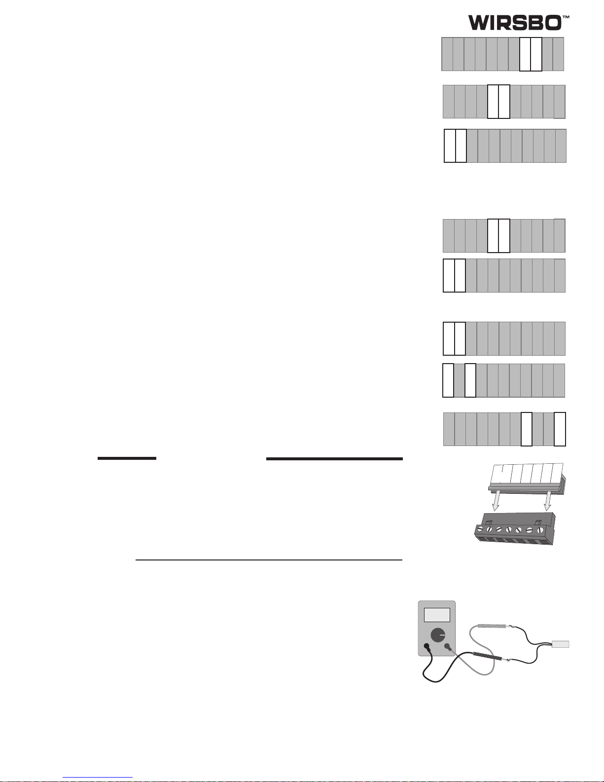
Test the Power Supply
Make sure exposed wires terminals are not in contact with other wires or grounded surfaces. Turn on the power and measure the
voltage between the
Power N — L
(15 and 16) terminals using an AC voltmeter, the reading should be between 110 and 130 V (ac).
Test the Powered Inputs
Mixing Demand (
Mix1 Demand & Mix2 Demand
)
If a mixing demand is used on the mixing 1 section, measure the voltage between the
Mix1 Demand
(1 and 2) terminals. When a call
for heat on the mixing 1 section is present, you should measure between 24 and 240 V (ac) at the terminals. When the demand is
gone, you should measure less than 5 V (ac).
If a mixing demand is used on mixing 2 section, measure the voltage between the
Mix2 Demand
(3 and 4) terminals. When a call for
heat on the mixing 2 section is present, you should measure between 24 and 240 V (ac) at the terminals. When the demand is gone,
you should measure less than 5 V (ac).
Test the Outputs
Mixing 1 System Pump (
Mix1 Pmp
)
If a mixing system pump is used in the mixing 1 section, make sure power to the terminal block is off and install a jumper between
the
N–Mix1Pmp
(11and12)terminals.Whenpowerisappliedtotheseterminals,themixingsystempump
Mix1Pmp
shouldstart.
If the pump does not turn on, check the wiring between the terminal block and the pump and refer to any installation or
troubleshooting information supplied with the pump. If the pump operates properly, disconnect the power and remove the jumper.
Mixing 2 System Pump (
Mix2 Pmp
)
If a mixing system pump is used in the mixing 2 section, make sure power to the terminal block is off and install a jumper between
the
N – Mix2 Pmp
( 7 and 8) terminals. When power is applied to these terminals, the mixing system pump
Mix2 Pmp
should start.
If the pump does not turn on, check the wiring between the terminal block and the pump and refer to any installation or
troubleshooting information supplied with the pump. If the pump operates properly, disconnect the power and remove the jumper.
Variable Speed Injection Pumps (
Var1 Pmp & Var2 Pmp
)
Ifthevariablespeed injectionpumpofthemixing 1sectionisused,make surepowertotheterminalblockis offandinstallajumper
between the terminals
N – Var1 Pmp
(13 and 14). When power is applied to terminals, the variable speed injection pump should
operate at full speed. If the pump does not operate, check the wiring between the terminal block and the pump and refer to any
installationortroubleshootinginformationsuppliedwiththepump.Ifthepumpoperatesproperly,disconnectthepowerandremove
the jumper.
Ifthevariablespeed injectionpumpofthemixing 2sectionisused,make surepowertotheterminalblockis offandinstallajumper
between the terminals
N – Var2 Pmp
(9 and 10). When power is applied to terminals, the variable speed injection pump should
operate at full speed. If the pump does not operate, check the wiring between the terminal block and the pump and refer to any
installationortroubleshootinginformationsuppliedwiththepump.Ifthepumpoperatesproperly,disconnectthepowerandremove
the jumper.
Boiler Enable
If a boiler is connected to the
Boiler Enable
(5 and 6) terminals, make sure power to the boiler circuit is off and install a jumper
between the terminals. When the boiler circuit is powered up, the boiler should fire. If the boiler does not turn on, refer to any
installation or troubleshooting information supplied with the boiler and/or Boiler Control. If the boiler operates properly, disconnect
the power and remove the jumper.
Connect the Control
• Make sure all power to the devices and terminal blocks is off and remove any remaining jumpers from the terminals.
•Reconnecttheterminalblockstothecontrolby carefullyaligningthemwiththeirrespectiveheadersonthecontrolandthenpushing
the terminal blocks into the headers. The terminal blocks should snap firmly into place.
Temperature Resistance Temperature Resistance Temperature Resistance Temperature Resistance
°F°CΩ°F°CΩ°F°CΩ°F°CΩ
-50 -46 506,000 20 -7 47,100 90 32 7,400 160 71 1,700
-40 -40 337,000 30 -1 34,400 100 38 5,780 170 77 1,390
-30 -34 228,000 40 4 26,700 110 43 4,730 180 82 1,180
-20 -29 166,000 50 10 19,900 120 49 3,740 190 88 977
-10 -23 116,000 60 16 15,000 130 54 3,100 200 93 838
0 -18 86,500 70 21 11,900 140 60 2,490 210 99 701
10 -12 61,700 80 27 9,170 150 66 2,010 220 104 606

DuoMix Installation Handbook
9
•Ifrequired,install the supplied safety dividers betweentheunpoweredsensorinputsandthe powered 120 V (ac) or 24V(ac)wiring
chambers.
• Do not apply power to the control until the DIP switches are properly set for your application. See the Settings section of
this brochure for details on how to set the DIP switches.
• Once the settings are complete, apply power to the control. The operation of the control on power up is described in the Sequence
of Operation section of this brochure.
Settings
Before adjusting the control settings, read through the Sequence of Operation section of this brochure to ensure that you understand
how the control operates.
STEP SIX ESSENTIAL CONTROL SETTINGS
Lock- Unlock DIP Switch
TheLock-UnlockDIPswitchisusedtoprevent unauthorizedpersons fromtamperingwiththesettings.WhentheDIPswitchisset toLock
( ) none of the settings may be adjusted. To adjust a setting simply switch the DIP switch to the Unlock ( ) position.
Run
Default settings
Default Settings DIP Switch
If the control settings have been erroneously set, the control can be made to operate with factory default
values by switching the
Default settings
DIP switch. In order to override all current settings with the factory
defaultvalues,thecontrolmustbepowereddownandpoweredupwiththeDIPswitchsetto
Defaultsettings
.
During normal operation set this DIP switch to
Run
.
MODES 1
The
MODES 1
adjustment selects the mode of operation for the mixing 1 section. There are three allowable
settings:
• OFF -Ifthemixing1sectionisnotused,theinstallershouldselectthissetting.Thecontrol
assumes the mixing 1 section is not used. All adjustments for the mixing 1 section
will be skipped.
• RST (reset) - When using the mixing 1 section for building space heating, the installer should
select this adjustment. The 201 control operates the mixing 1 section to provide
outdoor reset. This is the factory setting.
• SETP (setpoint) - When the installer requires a fixed supply water temperature, this setting must be
selected. The control operates the mixing 1 section to provide a fixed setpoint
temperature equal to the
SETPNT 1
temperature adjustment.
WWSD 1
WWSD 1
can be adjusted from 35 to 85°F, OFF (2 to 29°C). The mixing 1 section will shut down when the
outdoor temperature is warmer than this setting. The
WWSD
setting also has an effect in the setpoint mode
of operation. Factory setting is 68°F.
SETPNT 1
Ifsetpointmodeofoperationisselected,thecontroloperatesthevariablespeedinjectionpump1toprovide a
setpointtemperatureequaltothe
SETPNT1
setting.The
SETPNT1
settingcanbeadjustedfrom70to200°F
(21 to 93°C). An external mixing demand on the
Mix1 Demand
must be present. Factory setting is 110°F.
SENSOR 1
The
SENSOR1
adjustment informs the control which externaldevice is connected to the
Zo1/ Ind
terminal.
There are three allowable settings:
• NONE - If no indoor sensor or tekmar zone control is connected to the
Zo1/Ind
terminal, this setting must
be selected. This is the factory setting.
• INDR -Ifanindoorsensorisconnectedtothe
Zo1/Ind
terminal,thissettingmustbeselected.Thecontrol
will provide indoor temperature feedback in order to fine tune the supply water temperature.
• ZOIN - If a tekmar Zone Control is connected to the
Zo1/Ind
terminal, this setting must be selected. A
tekmar Zone Control provides indoor temperature feedback from multiple zones.
INDOOR 1
The
INDOOR1
setting can be adjusted from 35 to95°F(2 to 35°C). This setting should besetto the highest
desired indoor temperature in the mixing 1 section. Factory setting is 70°F.
°F
°F
°F

DuoMix Installation Handbook
10
°F
°F
DSGN RM1
This setting establishes the design room temperature on which the heat loss calculation was based. This
settingisusedbythe control to calculate the heating curve for the mixing1section.The
DSGNRM1
setting
can be adjusted from 35 to 95°F (2 to 35°C). Factory setting is 70°F.
DSN SUP 1
This setting establishes the design supply water temperature required in order to satisfy the heating
system at the design outdoor temperature. This setting is used by the control to calculate the heating curve
in the mixing 1 section. The
DSN SUP 1
setting can be adjusted from 80 to 220°F (27 to 104°C). Factory
setting is 110°F.
MAX SUP
The
MAX SUP 1
adjustment is used to set the highest allowable temperature in the mixing 1 section. This
setting can be adjusted from 100 to 220°F (38 to 104°C). Factory setting is 180°F.
OUT DSGN
The outdoor design temperature is obtained from local weather data. This setting can be adjusted from -50
to 30°F (-45 to -1°C). Factory setting is 10°F.
MODES 2
The
MODES 2
adjustment selects the mode of operation for the mixing 2 section. There are four allowable
Settings:
• OFF -Ifthemixing2sectionisnotused,theinstallershouldselectthissetting.Thecontrol
assumes the mixing 2 section is not used. All adjustments for the mixing 2 section
will be skipped.
• RST (reset) - When using the mixing 2 section for building space heating, the installer should
select this adjustment. The 201 control operates the mixing 2 section to provide
outdoor reset. This is the factory setting.
• SETP (setpoint) - When the installer requires a fixed supply water temperature, this setting must be
selected. The control operates the mixing 2 section to provide a fixed setpoint
temperature equal to the
SETPNT 2
temperature adjustment.
• SNOW (melting) - If section 2 is used for a snow melting application, the installer must select this
setting. The control then operates the mixing 2 section to regulate an outdoor slab.
WWSD 2
WWSD 2
can be adjusted from 35 to 85°F, OFF (2 to 29°C). The mixing 2 section will shut down when the
outdoor temperature is warmer than this setting. The
WWSD
setting also has an effect in the setpoint mode
of operation. Factory setting is 68°F.
SETPNT 2
Ifsetpointmodeofoperationisselected,thecontroloperatesthevariablespeedinjectionpump2toprovide a
setpointtemperatureequaltothe
SETPNT2
setting.The
SETPNT2
settingcanbeadjustedfrom70to200°F
(21 to 93°C). An external mixing demand on the
Mix2 Demand
must be present. Factory setting is 110°F.
SENSOR 2
The
SENSOR 2
adjustment informs the control which external device is connected to the
Zo2 /Ind
terminal.
There are three allowable settings:
• NONE - If no indoor sensor or tekmar zone control is connected to the
Zo2/Ind
terminal, this
setting must be selected. This is the factory setting.
• INDR - If an indoor sensor is connected to the
Zo2 /Ind
terminal, this setting must be selected.
The control will provide indoor temperature feedback in order to fine tune the supply
water temperature.
• ZOIN - If a tekmar Zone Control is connected to the
Zo2 /Ind
terminal, this setting must be
selected. A tekmar Zone Control provides indoor temperature feedback from multiple
zones.
INDOOR 2
The
INDOOR2
settingcanbeadjustedfrom35to95°F(2to35°C).Thissettingshouldbesettothehighest
desired indoor temperature in the mixing 2 section. Factory setting is 70°F.
°F
°F
°F
°F
°F

DuoMix Installation Handbook
11
°F
°F
°F
°F
°F
DSGN RM 2
This setting establishes the design room temperature on which the heat loss calculation was based. This
settingisusedbythecontroltocalculate the heating curve for the mixing 2 section. The
DSGNRM2
setting
can be adjusted from 35 to 95°F (2 to 35°C). Factory setting is 70°F.
DSN SUP 2
Thissettingestablishesthedesignsupplywatertemperaturerequiredinordertosatisfytheheatingsystem at
the design outdoor temperature. This setting is used by the control to calculate the heating curve for the
mixing 2 section. The
DSN SUP 2
setting can be adjusted from 80 to 220°F (27 to 104°C). Factory setting
is 110°F.
MAX SUP
The
MAX SUP 2
adjustment is used to set the highest allowable temperature in the mixing 2 section. This
setting can be adjusted from 100 to 220°F (38 to 104°C). Factory setting is 180°F.
MELTING
The
MELTING
settingisthedesiredslabtemperaturewhensnowmeltingisrequired.Itcanbeadjustedfrom
32 to 77°F (0 to 25°C). Factory setting is 36°F.
IDLING
The
IDLING
setting is the desired slab temperature during idling, and it can be adjusted from 20 to 68°F
(-7 to 20°C). If Idling is not desired, this setting must be set to
OFF
.
∆
T MAX
The 201 control limits the rate of heat applied to a slab to prevent excessive thermal stress. The rate of heat
delivery to the slab is dependant on the difference between the melting system supply and return
temperatures. The control measures these temperatures and calculates the difference to give the ∆T. If this
calculated ∆T approaches the
∆
T MAX
setting, the control operates the variable speed injection pump to
maintain the ∆T at the
∆
T MAX
setting. The
∆
T MAX
setting can be adjusted from 10 to 70°F (5 to 39°C).
Factory setting is 30°F.
CWCO (Cold Weather Cut Off)
CWCO
is the lowest temperature at which the melting system continues to operate. This temperature is set
basedonthecapacityofthesnowmeltsystemandtheeconomicsofmeltinginextremeconditions.Therange
ofthissettingisfrom-20to50°F(-29to10°C).The
CWCO
adjustmenthasan
OFF
positionforsystemswhere
a minimum outdoor temperature is not a consideration.
RUN TIME
The
RUNTIME
isset to the estimated timerequiredtocompletesnowmelting. This setting may beadjusted
from30min.to18hours.Forcontinuousoperationthe
RUNTIME
maybesetto
INF
(infinite).Factorysetting
is 4 hours. The snow melting run time will start counting down once the slab is up to
MELTING
temperature.
BOILER RETURN
To prevent problems of flue gas condensation in the boiler, the
Boil RET
adjustment is set to the minimum
boiler return temperature as specified by the boiler manufacturer. When the boiler return approaches this
setting, the control operates the variable speed pump to limit the output until the boiler return can warm up.
Ifa minimumboilerreturntemperatureis notrequired,aswithcondensing orelectricboilers, thisadjustment
can be set to
OFF
. This setting can be set from 70 to 180°F (21 to 82°C). Factory setting is 130°F.
UNITS (
°
F -
°
C)
The control can display temperatures in °C or °F. Factory setting is °F.
CONTRAST
In order to improve visibility of the Liquid Crystal Display (LCD) the
CONTRAST
of the display may be
adjusted.
BACKLITE
The
BACKLITE
on the display may be adjusted to OFF, 20 S, or ON. When it is adjusted to 20 S the display
is illuminated for 20 seconds after a button is pressed.
°F
View
Mix 1 Demand
Mix 2 Demand
Minimum
Maximum
Melting
Idling
CWCO
°F

DuoMix Installation Handbook
12
Description of Display Elements
1
%%
2
!
1
Variable speed output scale
Shows the speed of the injection pump1
or 2. Arrows show whether pumps are
speeding up or slowing down
Burner
Display when the Boiler Enable contact
is closed.
Pumps
Displays when mixing pumps 1 or 2 are
on.
2
Warning
Displays when an error is present
Lock-Unlock
Displays whether keypad is locked or
unlocked
WWSD
WWSD
Displays when control is in Warm Weather
Shut Down
Misc
°F°C
1
View
Adjust
!
WWSD
2
1
% %
2
ItemMenu
Menu
Displays the current
menu
Pointers
Show status of control
Status
Shows outputs of
control
{
Display
Displays temperatures, settings, and
items
{
Buttons
Selects Menu, Items
and adjusts settings
Start Stop

DuoMix Installation Handbook
13
Outdoor temperature
• If a mixing section is turned off, the
View Items
from that mixing section are
skipped.
• Dashes on the
TARGET
item denote heat is not required in that mixing section.
• Continue to press the
Item
button to toggle between view items.
• When attempting to see a given temperature and a sensor fault is present the
control displays "Err".
Target Mixing 1 Temperature Actual Mixing 1 Supply Temperature
Actual Mixing 2 Supply Temperature
ItemMenu
Start Stop
ItemMenu
Start Stop
ItemMenu
Start Stop
ItemMenu
Start Stop
ItemMenu
Start Stop
Boiler Return Temperature
°F
1
View Mix 1 Demand
Mix 2 Demand
Minimum
Maximum
Melting
Idling
CWCO
1
%
2
%
Target Mixing 2 Temperature
ItemMenu
Start Stop
°F
2
View Mix 1 Demand
Mix 2 Demand
Minimum
Maximum
Melting
Idling
CWCO
1
%
2
%
Target Mixing 2 Temperature
ItemMenu
Start Stop
°F
View Mix 1 Demand
Mix 2 Demand
Minimum
Maximum
Melting
Idling
CWCO
1
%
2
%
°F
1
View Mix 1 Demand
Mix 2 Demand
Minimum
Maximum
Melting
Idling
CWCO
2
%
1
%
°F
1
View Mix 1 Demand
Mix 2 Demand
Minimum
Maximum
Melting
Idling
CWCO
2
%
1
%
°F
1
View Mix 1 Demand
Mix 2 Demand
Minimum
Maximum
Melting
Idling
CWCO
2
%
1
%
2
°F
View Mix 1 Demand
Mix 2 Demand
Minimum
Maximum
Melting
Idling
CWCO
1
%
2
%
View Menu
RST (RESET) AND SETP (SETPOINT) MODE
To view the different items, continuously press the
Item
button.
• If an indoor sensor is selected in the
Adjust
menu, the actual indoor
temperature may be viewed.
• If a zone control is selected in the
adjust menu, the zone control target
temperature may be viewed.
Actual Section 1 indoor
Temperature
°F
1
View Mix 1 Demand
Mix 2 Demand
Minimum
Maximum
Melting
Idling
CWCO
1
%
°F
1
View Mix 1 Demand
Mix 2 Demand
Minimum
Maximum
Melting
Idling
CWCO
1
%
Zone Control Target
Temperature
OR
INDOOR SENSOR / ZONE CONTROL

DuoMix Installation Handbook
14
SNOW(SNOWMELTING)MODE
This display assumes that the Mixing 1 section is turned off and therefore no items for that section is present.
°F
2
View Mix 1 Demand
Mix 2 Demand
Minimum
Maximum
Melting
Idling
CWCO
°F
2
View Mix 1 Demand
Mix 2 Demand
Minimum
Maximum
Melting
Idling
CWCO
1
%
2
%
°F
2
View Mix 1 Demand
Mix 2 Demand
Minimum
Maximum
Melting
Idling
CWCO
1
%
2
%
°F
2
View Mix 1 Demand
Mix 2 Demand
Minimum
Maximum
Melting
Idling
CWCO
1
%
2
%
°F
2
View Mix 1 Demand
Mix 2 Demand
Minimum
Maximum
Melting
Idling
CWCO
1
%
2
%
°F
2
View Mix 1 Demand
Mix 2 Demand
Minimum
Maximum
Melting
Idling
CWCO
1
%
2
%
hr
2
View Mix 1 Demand
Mix 2 Demand
Minimum
Maximum
Melting
Idling
CWCO
1
%
2
%
°F
2
View Mix 1 Demand
Mix 2 Demand
Minimum
Maximum
Melting
Idling
CWCO
1
%
2
%
Outdoor temperature
• If a mixing 1 section is turned off, the
View Items
from that section are
skipped.
• Dashes on the
TARGET
item denote
heat is not required in that mixing
section.
• Continue to press the
Item
button to
toggle between view items.
• When attempting to see a given
temperature and a sensor fault is
present, the control displays "Err".
Target Mixing 2 Temperature Actual Mixing 2 Supply Temperature
Slab Target Temperature
ItemMenu
Start Stop
ItemMenu
Start Stop
ItemMenu
Start Stop
ItemMenu
Start Stop
ItemMenu
Start Stop
Actual Slab Temperature
1
%
2
%
∆T 2 (Temperature difference)
ItemMenu
Start Stop
Boiler Return Temperature
ItemMenu
Start Stop
Time Remaining
ItemMenu
Start Stop
Adjust Menu
ItemMenu
To enter the
Adjust
menu press the
Menu
button.
Adjust Adjust Adjust
Mixing 1 Section Off Mixing 1 Section in
Reset Mode Mixing 1 Section in
Setpoint Mode
MIXING 1 SECTION

DuoMix Installation Handbook
15
MIXING 1 IN RESET MODE
°F
Adjust
°F
Adjust
Item
Adjust
Item
°F
Adjust
Item
°F
Adjust
Warm Weather Shut
Down Input of Zo 1 / Ind Design Indoor
Temperature
°F
Adjust
Item Item
Desired Indoor
Temperature
Design Supply
Temperature Maximum Supply
Temperature Design Outdoor
Temperature
Item
Boiler Return
Temperature
°F
Adjust
°F
Adjust
MIXING 1 IN SETPOINT MODE
Warm Weather Shut
Down Desired Setpoint
Temperature
Item
°F
Adjust
Item
°F
Adjust
Design Outdoor
Temperature
°F
Adjust
Adjust
Mixing 2 Section Off Mixing 2 Section in
Reset Mode Mixing 2 Section in
Setpoint Mode
Adjust Adjust Adjust
Mixing 2 Section in
Snow Melting Mode
MIXING 2 SECTION
°F
Adjust
°F
Adjust Adjust
°F
Adjust
°F
Adjust
°F
Adjust
Item Item Item
Warm Weather Shut
Down Input of Zo 1 / Ind Design Indoor
Temperature
Item Item
Desired Indoor
Temperature
Design Supply
Temperature Maximum Supply
Temperature Design Outdoor
Temperature
Item
Boiler Return
Temperature
°F
Adjust
°F
Adjust
MIXING 2 IN RESET MODE

DuoMix Installation Handbook
16
Cold Weather Cut
Off
Item
°F
Adjust
Item
Adjust
Item
°F
Adjust
Item
hr
Adjust
°F
Adjust
Slab Melting
Temperature Slab Idling
Temperature Maximum ∆T
Melting Run Time
Maximum Supply
Temperature
°F
Adjust
Misc. Menu
Units (°F - °C)
Item
Misc
Item
Misc
°F
Misc
Display Contrast Display Backlight
THE CONTROL AUTOMATICALLY GOES BACK TO THE VIEW MENU WHEN THE BUTTONS ARE LEFT ALONE FOR 20 SECONDS
MIXING 2 IN SNOW MELTING MODE
MIXING 2 IN SETPOINT MODE
°F
Adjust
°F
Adjust
Warm Weather Shut
Down Desired Setpoint
Temperature
Item Item
Design Outdoor
Temperature
°F
Adjust


Display Menu
(Cont.)

DuoMix Installation Handbook
19
Testing the Control
STEP SEVEN OPERATIONAL TEST OF CONTROL FUNCTIONS
TheWirsboDuoMix 201 has a test routine which is usedtotest the main control functions. The 201 continually checksthesensorsand
displays an error message whenever a fault is found. See page 20 for the list of error messages. When the
Test
button is pushed, the
WWSD
display and the Minimum, Maximum, Melting, Idling, and CWCO pointers are turned off. The individual outputs and relays are
then tested in the following test sequence.
Test Sequence
Each step in the test sequence lasts 10 seconds. During the test routine, given a Mix demand is present, the test sequence can be
pausedbypressing the
Test
button.Once the testsequenceispaused, the
Test
buttoncan be pressedagaintoskip to the nextstep.
This can also be used to rapidly skip through the test sequence. To reach the desired step, repeatedly press and release the
Test
button until the appropriate device and indicator light turn on.
STEP 1 -
Thevariablespeedinjectionpump1(
Var1Pmp
)isrampedupto100%over10seconds. Ifthemixing1sectionisnotused
(i.e.
MODES 1
set to
OFF
)
N/A
is displayed and the pump is not operated.
STEP 2 -
Thevariablespeedinjectionpump1(
Var1Pmp
)isrampeddownto0%over10seconds.Ifthemixing1sectionisnotused
(i.e.
MODES 1
set to
OFF
)
N/A
is displayed and the pump is not operated.
STEP 3 -
The mixing 1 pump (
Mix1 Pmp
) is turned on for 10 seconds. If the mixing 1 section is not used (i.e..
MODES 1
set to
OFF
)
N/A
is displayed and the pump is not operated.
STEP 4 -
Thevariablespeedinjectionpump2(
Var2Pmp
)isrampedupto100%over10seconds. Ifthemixing2sectionisnotused
(i.e.
MODES 2
set to
OFF
)
N/A
is displayed and the pump is not operated.
STEP 5 -
Thevariablespeedinjectionpump2(
Var2Pmp
)isrampeddownto0%over10seconds.Ifthemixing2sectionisnotused
(i.e.
MODES 2
set to
OFF
)
N/A
is displayed and the pump is not operated.
STEP 6 -
The mixing 2 pump (
Mix2 Pmp
) is turned on for 10 seconds. If the mixing 2 section is not used (i.e.
MODES 2
set to
OFF
)
N/A
is displayed and the pump is not operated.
STEP 7 -
The
Boiler Enable
relay is turned on for 10 seconds.
Pointers "On"
Mix 1 Demand
• Mixing 1 section requires heat.
Mix 2 Demand
• Mixing 2 section requires heat.
Minimum
• The return temperature to the boiler is below the
Boil RET
setting and the 201 is reducing theload in
order to increase the boiler temperature as fast as possible.
Maximum
• Thesupplytemperatureof mixingsection1or2 isapproachingthe
MaxSup
settingandthe201 willnot
increase the supply temperature any further.
Melting
• The control is in melting mode.
Idling
• The control is in Idling mode.
CWCO
• The control is in Cold Weather Cut Off and heat for snow melting is not provided, unless the slab is
already up to temperature.
MAX HEAT Function
The
MAXHEAT
functionprovidesmaximumheattothesystembytargetingthemaximumsupplytemperatureforeachmixingsection.
This function is useful during system start up, manual override, or testing during the summer. When the control is in
MAX HEAT
and
a mixing demand in the mixing section 1 is present, the control turns on the mixing pump relay (
Mix1 Pmp
), the variable speed pump
output(
Var1Pmp
)and
BoilerEnable
relay.The
MAXHEAT
functionoverridestheWWSDandtheboilerminimumreturntemperature,
but it will not exceed the maximum supply setting. When a mixing demand in the mixing 2 section is present, the control operates
similarlyasexplainedabove.Thespeedoftheinjection pump(s)maybeadjustedusingthearrowkeystolimittheamountofinjection
desired. Once enabled, the
MAX HEAT
function operates for 24 hours or until any of the
Test
,
Menu
, or
Item
buttons are pressed.
See next page for setup instructions.

DuoMix Installation Handbook
20
View
1
%%
2
Press and Hold the Test
button for 3 seconds
ItemMenu
Test
Comfirm if
MAX HEAT
is
desired by pressing the
up or down button
ItemMenu
Test
View
1
%%
2
Control displays
MANUAL and the %
speed of the variable
speed pump(s)
1
ItemMenu
Test
2
View
1
%%
2
The % speed output may
be adjusted using the up
and down buttons
1
ItemMenu
Test
2
View
1
%%
2
To exit the
MAX HEAT
function presseither the
Test
,
Menu
or
Item
buttons
1
ItemMenu
Test
2
°F
View
1
%%
2
STEP EIGHT TROUBLESHOOTING
As in any troubleshooting procedure, it is important to isolate a problem as much as possible before proceeding. The Error Messages
and
Test
button greatly simplify troubleshooting of the 201. When the control is displaying an Error Message, identify the fault from the
look-up table on page 20 and follow standard testing procedures to confirm the problem. If you suspect a wiring fault, return to steps
three, four and five, and carefully check all external wiring and wiring connections.
Sensor and Internal Faults
Whenever a fault is detected in any of the sensors, an error message will be displayed in the LCD.
Outdoor Sensor Fault
When the outdoor sensor is open circuited or missing, the control will display
OUTDOOR OPEN
. If a short circuit occurs, the control
displays
OUTDOORSHRT
.Whenafaultwiththeoutdoorsensorispresent,thecontrolassumesafixedoutdoortemperatureof32°F.
During snow melting operation, the control assumes an outdoor temperature of 20°F.
Boiler Return Sensor Fault
WhentheBoilerReturnSensorisopencircuitedormissingandthe
BoilRET
adjustmentisnotsetto
OFF
),thecontrolwilldisplay
Boil
RET OPEN
. If a short circuit occurs, the control displays
Boil RET SHRT
. When a fault with the boiler return sensor is present, the
controlcontinuestooperateasifnoreturnsensorisinstalled.Ifthesystemisprovidingsnowmelting,themixing2sectionisturned off.
Supply 1 Sensor Fault
When the Supply Sensor of the mixing 1 section is open circuited or missing and
MODE 1
is not set to
OFF
, the control will display
SUPPLY 1 OPEN
. If a short circuit occurs, the control displays
SUPPLY 1 SHRT
. When a fault with the Supply Sensor is present,
the control shuts down the mixing 1 section.
Supply 2 Sensor Fault
Operates in a similar manner as the mixing 1 section.
IND / Zo 1
If
ZOIN
or
INDR
is selected and an open circuit is seen on the Zo 1/Ind terminal, the control will display
IND/Zo 1 OPEN
. If a short
circuit occurs, the control displays
IND/Zo 1 SHRT
. When a fault is present and
ZOIN
is selected, the control ignores any demands
from the zone control. If
INDR
is selected, the control provides outdoor reset but no indoor temperature feedback.
IND / Zo 2
Operates in a similar manner as the mixing 1 section.
Table of contents
Popular Control Unit manuals by other brands

Motroline
Motroline MC101 User& installer's manual

Power Dynamics
Power Dynamics 952.570 instruction manual

Bryant
Bryant SYSTXBBWEC01-B owner's manual

Dell EMC
Dell EMC MXG610s installation guide

Honeywell
Honeywell JADE W7220 Installation instructions and operators manual

ARDETEM
ARDETEM TPIs 2T User handbook

Nauticam
Nauticam 25624 instruction manual

VAT
VAT 162 Series Installation, operating, & maintenance instructions

Honeywell
Honeywell SILENT KNIGHT SK-FML installation instructions

Aurora
Aurora PVI-DESKTOP series Installation and operator's manual

Plymovent
Plymovent ICE-LC Product user manual

Caleffi solar
Caleffi solar 251 Series manual