Sitex NAVSTAR 10CF User manual

NavStar
Operation Manual

- 1 -
TABLE OF CONTENTS
NAVSTAR 10/12 Series
Welcome 6
NAVSTAR 10/12 Series
Introduction
Display Unit Installation 8
HOW GPSWORKS 11
#Sonar - How it works 13
Installation of GPS ANTENA
The installation of the GPS ANTENNA. 14
Installation of The Transducer
Display Unit Location 15
Display Unit Installation 15
Power Connection 16
Transducer Connection 16
Installing the Transducer Cable 18
Installing the Power Cable 19
Installing a Thru-Hull Transducer 20
Positioning the Transom-Mount Transducer 22
Mounting the Transom-Mount Transducer 23
Getting Started
1. The Keyboard 25
1.1. How to [PWR] use
2. Specification of the Connectors 27
3. Screen Overview 28
3.1. Chartplotter page
3.2. Sonar page
3.3. Navigation Data page
3.4. Highway page
3.5. Steering page
3.6. GPS Status page
4. Databar 34
4.1. Mode
4.2. Display
4.3. Position
5. Cursor 36
5.1. Calling the cursor

- 2 -
5.2. Moving
5.3. Removing the cursor
5.4. Cursor information window
5.5 .Cursor information window shown/hidden
6. Page 38
6.1. Page mode
6.2. Modify
7. Active 41
8. Navigation Data 42
8.1. Type
8.2. Edit
9. MOB 44
9.1. Inputing
9.2. Exiting the alarm
9.3. Removing
10. Memory Card 45
11. Save Userdata 46
11.1. WPT
11.2. Route
11.3. Track
11.4. User Line
11.5. User Name
12. Load Userdata 48
12.1. WPT
12.2. Route
12.3. Track
12.4. User Line
12.5. User Name
Chartplotter getting started
1. GOTO 51
1.1. Goto type1
1.2. Goto type2
2. WPT 52
2.1. List
2.2. Setting the WPT symbol
2.3. Setting WPT Color
2.4. Creating
2.5. Erasing
2.6. Erasing all of WPT
2.7. Moving the WPT
2.8. Navigating
2.9. Move to vessel
2.10. Sorting
2.11. Editing
3. Route 60
3.1. List

- 3 -
3.2. Route detail
3.3. Creating
3.4. Edit
3.5. Detail edit
3.6. Navigating
3.7. Erasing
4. Track 62
4.1. Track on/off
4.2. Choosing the track
4.3. Setting the thickness
4.4. Track Color
4.5. Track type
5. Measuring the distance and bearing 68
6. User Line 69
7. User Name 70
Chartplotter operation
1. Map Orientation 71
1.1. True Motion
1.2. North Up/South Up/East Up/West Up
1.3. Course Up
1.4. Head Up
2. Map setup 72
2.1. Map orientation
2.2. Userdata Display
2.3. Chart
2.4. C-Map (*Only for *C-MAP mode.)
3. Vessel 75
3.1. VesselIcon Size
3.2. Heading Line
3.3 Vessel style (Circle/Arrow/Vessel)
3.4. Orient. Resolution
4. Cursor Icon 76
5. Alarm 76
5.1. Navigation
5.2. Anchor
5.3. Interval
5.4. User Line
AIS getting started
1. What is AIS? 79
2. AIS system definitions 79
3. AIS information window 80
4. Quick INFO on AIS target 81

- 4 -
AIS operation
1. AIS on/off 82
2. List 82
2.1. List
2.2. Detail
2.3. Goto
2.4. Sort
3. Display Radius 84
4. AIS target size 84
5. Display vessels by Color 85
6. Display vessels by Type 85
7. Filter AIS types 85
8. Alarm 85
8.1. CPA Alarm
8.2. CPARange
8.3. TCPA Alarm
8.4. TCPA Range
8.5. Radius Alarm
8.6. Radius
8.7. Ignore Vessels if Speed Less
8.8. Speed less than
9. Set up AIS outs etc 86
9.1. Mark vessels as lost after
9.2. Remove lost vessels after
9.3. Vessel target
10. Others 86
10.1. Labels on vessels
10.2. Cursor Box info
10.3. Messages list
10.4. Test View
10.5. Fishing net
#Sonar getting started
1. Choosing the frequency 89
2. Auto/Manual Gain 89
3. Gain/STC 89
4. Controlling Gain 89
5. Controlling STC 90
6. Mode 90
6.1. Normal
6.2. Bottom Zoom
6.3. Bottom Lock
7. VRM 92

- 5 -
#Sonar operation
1. Menu 93
1.1. Userdata
1.2. Deep Depth Range
1.3. Shift
1.4. Mode
1.5. Bottom Zoom Range
1.6. Fish symbol
1.7. Fish size
1.8. Interference Rejection
1.9. Noise Rejection
2. Advanced Menu 94
2.1. Display
2.2. Color
2.3. Pulse
2.4. Output Power
2.5. Alarm
2.6. Water Temp
2.7. TD Setup
2.8. Speed Source
General operation
1. GPS 99
1.1. Coordinate System
1.2. Datum
1.3. LAT. Modification
1.4. LOT. Modification
1.5. POG filtering
1.6. COG filtering
1.7. SOG filtering
1.8. LAT/LON Unit
1.9. Receiving Port
2. Setup 100
2.1. Unit
2.2. Compass
2.3. Time & Date
2.4. Input/Output
2.5. Buzzer
2.6. Backlight time out
2.7. Customizing
2.8. TD Setup
3. Maintenance 105
3.1. Program Version
3.2. OS Version
3.3. MAP Version
3.4. Simulator
3.5. Language

- 6 -
3.6. Remote control setting
3.7. Initialization
3.8. Wire LAN
4. Calendar 106
5. Others 106
5.1. Screen capture
5.2. Capture List
5.3. Save User Setting
Data layout
1. Display 107
2. EDIT 107
2.1. Move
2.2. GPS
2.3. Time&Date
2.4. Userdata Display
2.5. Fishfinder
2.6. Unspecified
NS-12 series
General specification
GPS Receiver specification
Chartplotter specification
Sonar specification
Standard equipment configuration List
NS-10 series
General specification
GPS Receiver specification
Chartplotter specification
Sonar specification
Standard equipment configuration List
Customizing items
- 7 -
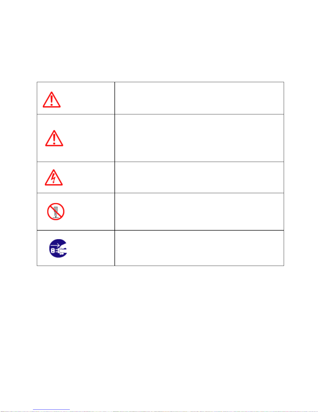
Pictorials
This manual uses the following symbols for easy understanding safety instructions. Always
follow these instructions carefully.
WARNING Always follow this safety instruction to prevent death or
injury.
CAUTION
Follow this safety instruction to avoid possible injury or
damage to your property.
Symbol “△” is a CAUTION or WARNING label indicating
the safety instruction.
WARNING This symbol is an Electrical Shock WARNING label.
Symbol is an instruction that you must not violate.
(This symbol instructs NOT to disassemble the system
components)
Symbol is an operation instruction that you must follow.
(This symbol shows the main power OFF instruction.)

- 8 -
WARNING <For System Operators>
Always follow this instruction to prevent death or personal injury.
Turn power
off
During
abnormality.
If smoke or a small of burning occurs, a fire or an
electrical short circuit may result. Turn the power switch
OFF and shut down the power supply immediately. Never
try to repair the system yourself. Call for service.
Do not open
Cabinet. High voltage exists in the instrument. Contact with voltage
may cause possible injury or death.
Do not touch
back
side of the
equipment.
Harmful line voltage is present on back side of the
equipment. Never try to touch back side while power is
turned on.
Avoid
excessive
shock
to display
unit.
The LCD display module contains a liquid. Do not apply
any mechanical shock to the display. If the display broken,
liquid may leak and injure your skin and eyes.
Do not use
with poor
ventilation.
If you cover this unit or use in an enclosed place, it may
malfunction or become damaged as a result of
overheating. Use only where there is sufficient ventilation.

- 9 -
Installation Cautions <For service Personnel>
Follow installation instructions to avoid personal injury and system malfunction.
Installation in
rigid location. Mount your NAVSTAR 10/12 on a rigid frame or base to prevent your
unit from working loose.
Use correct
Installation
materials.
Use the installation materials provided in the standard accessory pack
only. If you use hardware of insufficient strength, your system may
loosen causing damaged.
Keep away from
direct sunlight. Keep your system out of direct sunlight as it may become damaged by
overheating.
Keep away from
water. Take care not to get water on or in your unit as it may be damaged
and/or cause an electrical shock.
Keep away from
heat source. Keep your system away from other heat source as it may malfunction,
be damaged, or burn.
Use correct
power source. Operate your system within the specified power voltage. An incorrect
power supply may cause

- 10 -
Maintenance Cautions<For Maintenance Personnel>
Use the following safety precaution internal inspection.
Discharge
capacitors. High voltage may be retained in the capacitors if the high-tension
circuit several minutes after you have turned the power switch off.
Check that
power is OFF
To prevent an electrical injury due to erroneous power switching,
make sure that the main power supply and the system power switch
are both in the off position. Additionally, attach a safety label
showing that service is in progress.
Avoid EMI. Take care not to damage the ESDs (Electrostatic Sensitive Devices)
by static electricity from carpet and cloths.
Avoid dust. Wear a safety mask so as not to breath in dust during inspection or
cleaning inside your system instruments.

- 11 -
Operation Notes <For operators>
Observe the following operation notes, otherwise the system failure or deterioration can result. And
periodical inspection and maintenance are required for keeping the system in an optimum condition.
Backup important
data.
The waypoint and other registered data may become
unreadable by unexpected failure. We recommend
recording this data separately.
Use correct
transducer only.
If you use incorrect transducer, the transmitter circuit may
be damaged due to a matching error. Consult is for
system information.
Check transducer
Connection
before
power on
Do not turn the power switch ON if the transducer is
disconnected or if it is not inserted into the water. If done,
the transducer or transmitter circuit may be damaged.
Always clean the
transducer
Since transducer performance can drop due to
accumulated bottom growth, keep the transducer clean.
Never paint transducer surface.
Transducer must
be installed by
authorized
personnel.
Consult us for transducer installation by authorized
personnel.
WARNING
This product is designed to assist a navigation.
When you are sailing, use the certified chart from the
Government or IMO.

- 12 -
NAVSTAR 10/12 Series
Welcome
The NAVSTAR 10/12 Series Color LCD Chartplotter & Fishfider Systems employs the latest in proven
technology to provide accurate fish & bottom information. The Plotter functions of NAVSTAR 10/12
series are totally dependent upon the capability of the navigation source to provide accurate position
information. This device is only an aid to navigation. It should be used in conjunction with all other
navigation accuracy. For safety, always resolve any uncertainty before continuing navigation.
CAUTION
There is no direct relationship between the color of water areas and their depth. The navigator shall
always query the area for depth information and use the official paper chart.
CAUTION
The performance of LCD displays are degraded by continuous direct exposure to ultraviolet rays.
Locate your NAVSTAR 10/12 series Display away from direct sunlight. When not in use. Keep the
display covered. DISPLAY BREAKAGE WARNING
The LCD display module contains a liquid. If the display is broken and the liquid contacts your skin,
wash it off immediately in running water for 15 minutes. If the liquid contacts your eyes, immediately
flush your eyes with running water for 15 minutes. Contact a physician if any abnormal symptom is
experienced.

- 13 -
INDICATION NOTICE
*: It is important or warning notice on front of article
[ ]: Keyboard.

- 14 -
NAVSTAR 10/12 series Introduction
Fix Text Below, so that Words Do Not Separated Strangely at End of each Line.
For centuries, sailors have been searching for a reliable and precise method of travelling the world’s
waterways. From celestial navigating to the modern navigation techniques as Loran, Decca navigator,
Omega or Transit Satnav, each system has had its problems with weather, range and reliability.
Without doubt, the “Global Positioning System”, or GPS for short, is the most significant advance in
navigation: it provides the navigator a position 24 hours a day, 365 days a year in any weather
condition. GPS is a satellite based navigation system which provides suitably equipped users with
accurate position, velocity and time data. Originally the GPS, developed by the U.S. Department of
Defense, was conceived for military purposes, but now it is used in a host of civilian applications.
GPS navigation uses satellite signals to determine your position in relation to a set of satellites orbiting
the earth. The GPS constellation of satellites continuously sends radio signals, containing the precise
position for each satellite back to earth. By knowing the position of 3 or 4 satellites and calculating
various time differences between transmitted signals, the GPS receiver can determine its present
position anywhere on earth, and thanks to continuous updates, calculate speed and course
information.
Display Unit Installation
Temporarily install the mounting bracket on the Genesis display unit and place the unit at the selected
location.
CAUTION
The Smart4/5 series display unit is unstable when the mounting bracket is not secured. Hold the unit in
place at all times.
Check the suitability of the location and make any adjustments. When all is satisfactory, use the holes
in the mounting bracket as a guide and mark the holes locations on the mounting surface.
Drill a 1/4 in. diameter hole at each marked location. Mount the NavStar series display bracket using

- 15 -
bolts through the mounting surface. Place large flat washers on the opposite side of the mounting
surface from the bracket and then install lock washers and nuts. Tighten securely.
Install the display unit into the mounting bracket. Check alignment and operation of the pivots and
security of the mounting. Make any adjustments necessary to prevent binding and assure even
meshing of the pivot locking washers. It is advised to remove the display unit and store it in a safe
place to prevent damage during the rest of the installation process.
[Mounting Bracket]

- 16 -
[Flush Mounting]

- 17 -
NAVSTAR 10/12 series Introduction
HOW GPS WORKS
Currently, the GPS constellation consists of 26 orbiting satellites (including 3 spares), but this number
will increase in the future.
The GPS receiver computes an accurate position by calculating the distance to the GPS satellites that
orbit the earth. Signals are required from 3 satellites for two dimensional (2D) position calculation
whilst 4 satellites are required for three dimensional (3D) position calculation.
As mentioned earlier, GPS satellites are not geostationary, but they are orbiting the earth as illustrated
on the following figure:
[The GPS constellation]
Note that position is repeatedly fixed through the following three steps while any 3 satellites are in line
of sight.
The position calculation procedure is indicated in the following three steps:
1. GPS satellites continuously transmit their own precise orbital data and the GPS receiver computes
their locations by receiving this data.
2. In this receiving process, the GPS receiver measures very accurate distances to the satellites, using
the "Spread Spectrum Modulation" method. Excellence in GPS's position-fixing accuracy is mainly due
to this technology.
3. When the satellite locations and their distances are known, the GPS receiver fixes its own position
by triangulation:

- 18 -
NAVSTAR 10/12 series Introduction
[The GPS position calculation]
As illustrated in the previous figure, the position is calculated as the meeting point of three
spheres, which are drawn around the three satellites with diameters d1, d2 and d3.
Position Fixing Accuracy: HDOP
The GPS fix accuracy is due to the locations of 3 satellites in the sky. High accuracy is obtainable
when the satellites are widely scattered in the sky; on the
contrary, accuracy is reduced when the satellites have gathered in a narrow space. In the following
figure, in both cases it is possible to obtain the GPS fix, but in the left case the accuracy will be higher
than the right:
[HDOP]
The index for position-fixing accuracy is called HDOP ("Horizontal Dilution Of Precision"). The smaller
the HDOP value, the more accurately the position can be fixed.

- 19 -
NAVSTAR 10/12 series Introduction
#Sonar - How it works-
The NAVSTAR 10/12CF sonar consists of a transceiver display unit and a dual frequency transducer.
An electronic signal pulse is generated in the transmitter section of the display unit. When coupled to
the transducer, this signal is converted into an ultrasonic signal and is transmitted toward the bottom.
The signal travels through the water until it strikes an object or the bottom. It is reflected back , hits the
transducer surface, and is reconverted into an electronic signal by the transducer. Then it is amplified
in the receiver section, processed in the main logic section, and displayed, as an image on a LCD
screen. (Picture 3)
When your boat travels from point A to point B as shown in Picture 1, the beam of the transducer
installed on your boat shown a cross-sectional view in the water.
Picture 2 indicates a cutaway view under the water when your boat moves from Ato point B.
The screen shows the latest scan data at its right position. After the next
scan, the previous data is moved to the left and the latest scan data is
shown at the right position. When your boat moves from point A to point
B, the screen shows the scan data as shown in Picture 3.
This manual suits for next models
3
Table of contents
Other Sitex GPS manuals


