manuals.online logo
Brands
  1. Home
  2. •
  3. Brands
  4. •
  5. Manitowoc
  6. •
  7. Construction Equipment
  8. •
  9. Manitowoc 15000 3 Series User manual

Manitowoc 15000 3 Series User manual

8631-A, 8-12-05/GA
Page 1 of 3
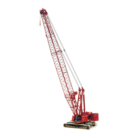
15000 SERIES 3, 4Luffing Jib Raising Procedure
Luffing Jib No. 149A On Boom No. 57
Manitowoc Cranes, Inc.
Manitowoc, Wisconsin 54220 U.S.A.
Recommended boom and luffing jib raising and lowering procedure
15000 SERIES 3 equipped with 99 740 kg crane counterweight and 36 290 kg carbody counterweight and 15000 SERIES 4
equipped with 107 680 kg crane counterweight and 52 160 kg carbody counterweight for raising and lowering boom and luffing jib
combinations. Refer to luffing jib rigging assembly No. A08947 for proper make-up of inserts, straps, pendants and miscellaneous
parts, etc. and to luffing jib operator’s manual.
Two methods may be used to raise and lower boom and luffing jib combinations.
A. Layout In-Line Method
Boom and luffing jib are assembled in layout, end to end, position. Boom and luffing jib must be inline over end of blocked
crawlers prior to raising boom and luffing jib. Slowly raise boom until angle between boom to luffing jib is approximately
172 degrees. Jib stop pins should engage automatically when inner strut is fully retracted. Visually observe that these pins are
fully engaged before raising boom and jib. Tighten luffing jib suspension with luffing jib hoist. Boom and luffing jib can then
be raised simultaneously using only the boom hoist. Reverse this procedure when lowering boom and luffing jib.
Boom and luffing jib combinations in table below may be raised and lowered using layout in-line method.
LAYOUT IN-LINE METHOD - 15000 SERIES 3, 4
Maximum Boom and Luffing Jib Lengths Lifted Unassisted
Over End Of Blocked Crawlers
Boom Length
Luffing Jib No. 149A
Without
Intermediate Fall With
Intermediate Fall
Feet Meters Feet Meters Feet Meters
80.4 24.5 70 - 190 21.3 - 57.9 70 - 180 21.3 - 54.9
90.2 27.5 70 - 180 21.3 - 54.9 70 - 170 21.3 - 51.8
100.1 30.5 70 - 170 21.3 - 51.8 70 - 160 21.3 - 48.8
109.9 33.5 70 - 160 21.3 - 48.8 70 - 150 21.3 - 45.7
119.8 36.5 70 - 150 21.3 - 45.7 70 - 130 21.3 - 39.6
129.6 39.5 70 - 130 21.3 - 39.6 70 - 120 21.3 - 36.6
139.4 42.5 70 - 120 21.3 - 36.6 70 - 110 21.3 - 33.5
149.3 45.5 70 - 100 21.3 - 30.5 70 - 90 21.3 - 27.4
159.1 48.5 70 - 80 21.3 - 24.4 70 21.3
169.0 51.5 70 21.3
Load blocks, hook and weight ball on ground until boom and luffing
jib are erected.
8631-A, 8-12-05/GA
Page 2 of 3
15000 SERIES 3, 4
Luffing Jib Raising Procedure
Luffing Jib No. 149A On Boom No. 57
Manitowoc Cranes, Inc.
Manitowoc, Wisconsin 54220 U.S.A.
B. Layout Jack-Knife Method
Longer boom and luffing jib combinations must be raised and lowered using this method.
Caution: Anytime luffing jib point rollers are in contact with ground during raising or lowering procedure, disengage swing
lock and release swing brake.
Raising:
Boom and luffing jib are assembled in layout, end to end, position. Boom and luffing jib must be inline over end of blocked
crawlers prior to raising boom and luffing jib. Luff up jib strut until straps on insert next to butt are clear of strap brackets
(jib strut at approximately 60 degrees). Slowly raise boom until angle between boom to luffing jib is approximately
172 degrees. Jib stop pins should engage automatically when inner strut is fully retracted. Visually observe that these pins are
fully engaged before raising boom and jib. Boom is then raised while luffing jib point rollers roll on ground. Tension should
be applied to luffing jib hoist to keep luffing jib strut off luffing jib during boom raising. Boom up until boom to luffing jib
angle reaches value specified in tables or vertical, whichever occurs first. Tighten luffing jib suspension with luffing jib hoist.
Boom and luffing jib are then raised together using boom hoist until boom reaches 85 degrees. Luffing jib radius must be
within capacity chart before swinging over side of machine. Boom may then be adjusted to desired operating angle.
Lowering:
Position boom at 85 degrees with boom and luffing jib inline over end of blocked crawlers prior to lowering luffing jib. Set load
blocks, hook and weight ball on ground before lowering boom and luffing jib to ground. Lower luffing jib until boom to luffing
jib angle reaches value specified in tables. Lower boom until luffing jib point rollers contact ground. If luffing jib is hanging at
or near vertical, raise luffing jib a few degrees forward of vertical to allow luffing jib to roll out. Caution: Be careful not to
damage upper jib point after contacting ground by booming down and rollers not wanting to roll out. Continue to lower boom
while luffing jib rollers roll on ground. Keep enough tension on luffing jib hoist to keep luffing jib strut off luffing jib. Stop
lowering boom when boom to luffing jib angle is approximately 168 degrees. Disengage luffing jib stop strut pins and lower
boom onto blocking.
Boom and luffing jib combinations in following tables require layout jack knifing to a specified boom to luffing jib angle for raising
and lowering.
Refer to column A for Maximum Number of Lower Boom PointSheaves allowed. Boom lengths shown with an asterick (*) require
lower boom point to be removed.
8631-A, 8-12-05/GA
Page 3 of 3
15000 SERIES 3, 4Luffing Jib Raising Procedure
Luffing Jib No. 149A On Boom No. 57
Manitowoc Cranes, Inc.
Manitowoc, Wisconsin 54220 U.S.A.
LAYOUT JACK-KNIFE METHOD - 15000 SERIES 3
Maximum Boom and Luffing Jib Lengths Lifted Unassisted
Over End Of Blocked Crawlers
Boom Length
Luffing Jib No. 149A A
Maximum
Number of
Lower
Boom Point
Sheaves
Boom Length
Luffing Jib No. 149A A
Maximum
Number of
Lower
Boom Point
Sheaves
Without
Intermediate Fall
Boom To
Luffing Jib
Angle With
Intermediate Fall
Boom To
Luffing Jib
Angle
Feet Meters Feet Meters Degrees Feet Meters Feet Meters Degrees
80.4 24.5 200 - 240 61.0 - 73.2 90 8 80.4 24.5 190 - 240 57.9 - 73.2 90 8
90.2 27.5 190 - 240 57.9 - 73.2 90 8 90.2 27.5 180 - 240 54.9 - 73.2 90 8
100.1 30.5 180 - 240 54.9 - 73.2 90 8 100.1 30.5 170 - 240 51.8 - 73.2 90 8
109.9 33.5 170 - 240 51.8 - 73.2 90 8 109.9 33.5 160 - 240 48.8 - 73.2 90 8
119.8 36.5 160 - 240 48.8 - 73.2 90 8 119.8 36.5 140 - 240 42.7 - 73.2 90 8
129.6 39.5 140 - 240 42.7 - 73.2 90 8 129.6 39.5 130 - 240 39.6 - 73.2 60 8
139.4 42.5 130 - 240 39.6 - 73.2 60 8 139.4 42.5 120 - 240 36.6 - 73.2 60 8
149.3 45.5 110 - 240 33.5 - 73.2 60 8 149.3 45.5 100 - 240 30.5 - 73.2 60 8
159.1 48.5 90 - 240 27.4 - 73.2 60 8 159.1 48.5 80 - 240 24.4 - 73.2 60 8
169.0 51.5 80 - 240 24.4 - 73.2 60 8 169.0 51.5 70 - 240 21.3 - 73.2 60 8
*178.8 54.5 70 - 240 21.3 - 73.2 60 0 *178.8 54.5 70 - 230 21.3 - 70.1 60 0
*188.7 57.5 70 - 190 21.3 - 57.9 60 0 *188.7 57.5 70 - 170 21.3 - 51.8 60 0
Load blocks, hook and weight ball on ground until boom and luffing jib are erected.
LAYOUT JACK-KNIFE METHOD - 15000 SERIES 4
Maximum Boom and Luffing Jib Lengths Lifted Unassisted
Over End Of Blocked Crawlers
Boom Length
Luffing Jib No. 149A A
Maximum
Number of
Lower
Boom Point
Sheaves
Boom Length
Luffing Jib No. 149A A
Maximum
Number of
Lower
Boom Point
Sheaves
Without
Intermediate Fall
Boom To
Luffing Jib
Angle With
Intermediate Fall
Boom To
Luffing Jib
Angle
Feet Meters Feet Meters Degrees Feet Meters Feet Meters Degrees
80.4 24.5 200 - 240 61.0 - 73.2 90 8 80.4 24.5 190 - 240 57.9 - 73.2 90 8
90.2 27.5 190 - 240 57.9 - 73.2 90 8 90.2 27.5 180 - 240 54.9 - 73.2 90 8
100.1 30.5 180 - 240 54.9 - 73.2 90 8 100.1 30.5 170 - 240 51.8 - 73.2 90 8
109.9 33.5 170 - 240 51.8 - 73.2 90 8 109.9 33.5 160 - 240 48.8 - 73.2 90 8
119.8 36.5 160 - 240 48.8 - 73.2 90 8 119.8 36.5 140 - 240 42.7 - 73.2 90 8
129.6 39.5 140 - 240 42.7 - 73.2 90 8 129.6 39.5 130 - 240 39.6 - 73.2 90 8
139.4 42.5 130 - 240 39.6 - 73.2 90 8 139.4 42.5 120 - 240 36.6 - 73.2 90 8
149.3 45.5 110 - 240 33.5 - 73.2 90 8 149.3 45.5 100 - 240 30.5 - 73.2 60 8
159.1 48.5 90 - 240 27.4 - 73.2 60 8 159.1 48.5 80 - 240 24.4 - 73.2 60 8
169.0 51.5 80 - 240 24.4 - 73.2 60 8 169.0 51.5 70 - 240 21.3 - 73.2 60 8
*178.8 54.5 70 - 240 21.3 - 73.2 60 0 *178.8 54.5 70 - 230 21.3 - 70.1 60 0
*188.7 57.5 70 - 190 21.3 - 57.9 60 0 *188.7 57.5 70 - 170 21.3 - 51.8 60 0
*198.5 60.5 70 - 130 21.3 - 39.6 60 0 *198.5 60.5 70 - 110 21.3 - 33.5 60 0
Load blocks, hook and weight ball on ground until boom and luffing jib are erected.
This manual suits for next models

1

Other Manitowoc Construction Equipment manuals

Manitowoc Shuttlelift CD3300 Series User manual

Manitowoc

Manitowoc Shuttlelift CD3300 Series User manual

Manitowoc Grove RT890E User manual

Manitowoc

Manitowoc Grove RT890E User manual

Manitowoc MLC150-1 User manual

Manitowoc

Manitowoc MLC150-1 User manual

Manitowoc MLC650 User manual

Manitowoc

Manitowoc MLC650 User manual

Manitowoc National Crane 600E-2 User manual

Manitowoc

Manitowoc National Crane 600E-2 User manual

Manitowoc Grove GRT8100 User manual

Manitowoc

Manitowoc Grove GRT8100 User manual

Manitowoc National Crane NBT50 Series User manual

Manitowoc

Manitowoc National Crane NBT50 Series User manual

Manitowoc Grove TMS800E Installation and user guide

Manitowoc

Manitowoc Grove TMS800E Installation and user guide

Manitowoc Grove RT9150E User manual

Manitowoc

Manitowoc Grove RT9150E User manual

Manitowoc 2250 2 Series User manual

Manitowoc

Manitowoc 2250 2 Series User manual

Manitowoc MLC300 User manual

Manitowoc

Manitowoc MLC300 User manual

Manitowoc National Crane NBT40-1 Series User manual

Manitowoc

Manitowoc National Crane NBT40-1 Series User manual

Manitowoc Grove GMK6300L-1 User manual

Manitowoc

Manitowoc Grove GMK6300L-1 User manual

Manitowoc MLC80A-1 User manual

Manitowoc

Manitowoc MLC80A-1 User manual

Manitowoc 2250 2 Series User manual

Manitowoc

Manitowoc 2250 2 Series User manual

Manitowoc Grove RT530E-2 User manual

Manitowoc

Manitowoc Grove RT530E-2 User manual

Manitowoc Grove 5540F User manual

Manitowoc

Manitowoc Grove 5540F User manual

Manitowoc 14000 User manual

Manitowoc

Manitowoc 14000 User manual

Manitowoc 999 Installation and user guide

Manitowoc

Manitowoc 999 Installation and user guide

Manitowoc 31000 User manual

Manitowoc

Manitowoc 31000 User manual

Manitowoc Grove RT9150E User manual

Manitowoc

Manitowoc Grove RT9150E User manual

Manitowoc Grove GRT655 User manual

Manitowoc

Manitowoc Grove GRT655 User manual

Manitowoc Grove 5540F User manual

Manitowoc

Manitowoc Grove 5540F User manual

Manitowoc NATIONAL CRANE 900A User manual

Manitowoc

Manitowoc NATIONAL CRANE 900A User manual

Popular Construction Equipment manuals by other brands

Graco 231-133 B Instructions-parts list

Graco

Graco 231-133 B Instructions-parts list

probst KIG-I operating instructions

probst

probst KIG-I operating instructions

Upright SB85J Operator's manual

Upright

Upright SB85J Operator's manual

Ammeraal Beltech uni Plastic Modular Belt Series Assembly

Ammeraal Beltech

Ammeraal Beltech uni Plastic Modular Belt Series Assembly

Be Cool BC90LEF2202 Operation manual

Be Cool

Be Cool BC90LEF2202 Operation manual

Silverline 794339 manual

Silverline

Silverline 794339 manual

Sealey PBS90.V2 instructions

Sealey

Sealey PBS90.V2 instructions

Hunnebeck BOSTA user guide

Hunnebeck

Hunnebeck BOSTA user guide

Leach ALPHA III Maintenance manual

Leach

Leach ALPHA III Maintenance manual

Graco 25C528 Instructions - parts

Graco

Graco 25C528 Instructions - parts

Husqvarna DCR 300 Operator's manual

Husqvarna

Husqvarna DCR 300 Operator's manual

MULTIQUIP ESSICK EM90SLF Operation manual

MULTIQUIP

MULTIQUIP ESSICK EM90SLF Operation manual

TEUFELBERGER TREEJACK Manufacturer's information and instructions for use

TEUFELBERGER

TEUFELBERGER TREEJACK Manufacturer's information and instructions for use

Volvo ECR50D Operator's manual

Volvo

Volvo ECR50D Operator's manual

Komatsu WA95-3 Operation & maintenance manual

Komatsu

Komatsu WA95-3 Operation & maintenance manual

E-Z DRILL 110B Setting up

E-Z DRILL

E-Z DRILL 110B Setting up

MetalTech BuildMan I-BMSO4 OPERATIONAL SAFETY AND ASSEMBLY INSTRUCTIONS

MetalTech

MetalTech BuildMan I-BMSO4 OPERATIONAL SAFETY AND ASSEMBLY INSTRUCTIONS

Sealey 500KC.V2 instructions

Sealey

Sealey 500KC.V2 instructions

manuals.online logo
manuals.online logoBrands
  • About & Mission
  • Contact us
  • Privacy Policy
  • Terms and Conditions

Copyright 2025 Manuals.Online. All Rights Reserved.