SKF Lincoln 3669 Parts list manual

Assembly and operation instructions
Model 3669
17 U.S. gallon portable
low profile drain with electric pump
Date of issue February 2018
Form number 404513
Version 2

Contents
Safety . . . . . . . . . . . . . . . . . . . . . . . . . . . 3
Explanation of signal words
for safety . . . . . . . . . . . . . . . . . . . . . . . . . 3
Specifications . . . . . . . . . . . . . . . . . . . . . 3
Assembly . . . . . . . . . . . . . . . . . . . . . . . . 4
Usage . . . . . . . . . . . . . . . . . . . . . . . . . . . 5
Drain operation. . . . . . . . . . . . . . . . . . . . 5
Discharge operation . . . . . . . . . . . . . . . . 5
Parts list . . . . . . . . . . . . . . . . . . . . . . . . . 7
Kits list*. . . . . . . . . . . . . . . . . . . . . . . . . . 7
Troubleshooting . . . . . . . . . . . . . . . . . . . 8
Warranty . . . . . . . . . . . . . . . . . . . . . . . . 12
2

NOTE
Emphasizes useful hints and
recommendations as well as
information for efficient and trouble-
free operation.
CAUTION
Indicates a dangerous situation that can
lead to light personal injury or property
damage if precautionary measures are
ignored.
WARNING
Indicates a dangerous situation that
could lead to death or serious injury if
precautionary measures are ignored.
DANGER
Indicates a dangerous situation that will
lead to death or serious injury if
precautionary measures are ignored.
Explanation of signal
words for safety
Table 1
Specifications
Reservoir and pump
Capacity 17 U.S. gal (64 liters)
Casters 4 in (101 mm)
Electric pump 115 V AC, 50/60 Hz, 2 A
Extractor hose length 6 ft. (1,8 m)
Pumping capacity 350 gph (1 324 lph)
Pump maximum oil temperature 160 °F (71 °C)
Pump minimum oil temperature 40 °F (4,4 °C)
Pump type Impeller
Duty cycle: intermittent Maximum 30 minutes
Thermal protection Automatic
Motor amps 1.40 A
Pump material
Body Bronze SS
Motor shaft 303 SS
Retainer ring BL-22
Cover SS
Screws SS
Pump gasket Non ASB
Lip seal Nitrile
Impeller Nitrile
Safety
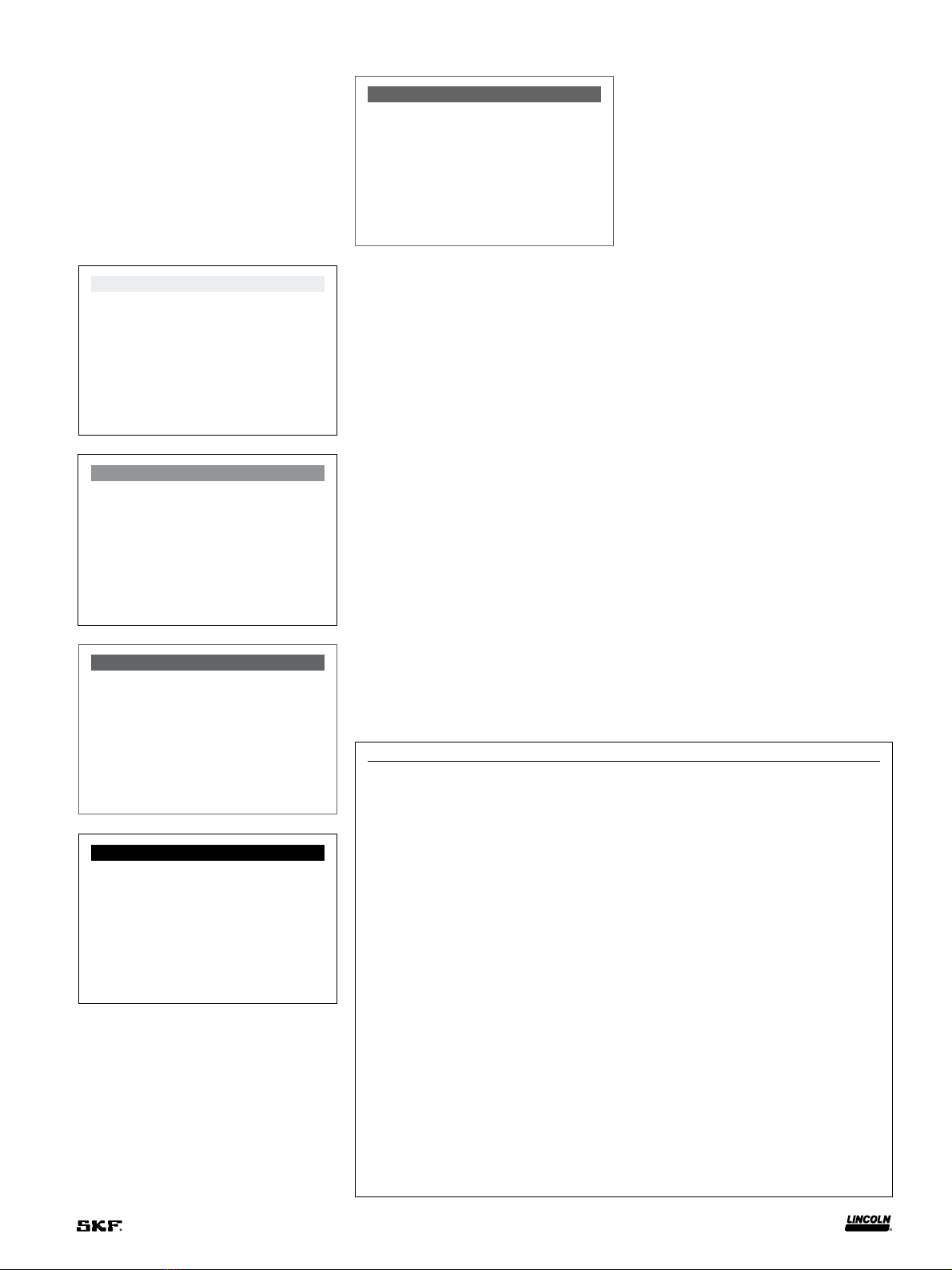
Read and carefully observe all assembly,
operating and troubleshooting instructions
before starting these procedures. The truck
drain must be assembled, maintained and
repaired exclusively by persons familiar with
the instructions in this manual.
Assemble and operate the truck drain only
after safety instructions , warnings and pro-
cedures have been read and are completely
understood.
Adequate personal protection must be
used to prevent splashing of material on the
skin or in the eyes.
Always disconnect power source (lock
out/tag out) before starting installation of
this equipment. Never assemble or disas-
semble the truck drain while connected to a
power source.
Any other use not in accordance with
instructions in this manual will result in loss
of claim for warranty or liability.
• Do not use the drain on surfaces that are
covered with oil or grease.
• Do not use the drain on surfaces that are
not flat and level.
• Do not exceed the drain load capacity.
• Do not allow the load to become uneven.
• Do not allow anyone in the vehicle while
using the drain.
• Do not drain oil above 160 °F (71 °C) into
the drain.
• Do not use the drain near flames or
heat sources.
• Do not misuse, over-pressurize, modify
parts, or use worn and/or damaged parts.
• Do not use the drain on a vehicle that
is running.
• Dispose of used oil properly.
• Failure to comply may result in personal
injury and/or damage to equipment.
WARNING
Read manual prior to installation or use
of this product. Keep manual nearby for
future reference. Failure to follow
instructions and safety precautions may
result in death or serious injury.
3

Assembly
NOTE
Reservoir hose, evacuator hose, hose
clamps, hose fittings and handle bolts
are shipped inside reservoir (1).
NOTE
To prevent cutting or pinching electric
cord route cord away from mounting
bracket and toward bottom/front of
electric motor.
1 Refer to Fig. IPB 1 and place electric
pump (6) under mounting bracket (15).
2 Install bolts (10) through top of
bracket (15) and into pump
mounting holes (6).
3 Install nuts (5) on bolts (10).
4 Using a 5/32 in hex head wrench and 7/16
in wrench, hold nut (5) and
tighten bolt (10).
11 Refer to Fig. IPB 2 and position
handle (12) in slot of mounting
bracket (15).
12 Install bolts (13) into holes of reservoir
mounting bracket (15) and threaded
holes of handle (12).
13 Install adapter fitting (4) and extractor
hose (3) onto electric pump outlet (17)
and tighten.
14 Place filter screen (2) on reservoir (1).
5 Refer to Fig. IPB 2 and slide hose
clamps (8) over both ends of short 8 in
(203 mm) reservoir hose (9).
6 Insert garden hose thread (GHT) to hose
barb fitting (7) into short 8 in (203 mm)
reservoir hose (9).
7 Connect end of 8 in (203 mm) reservoir
hose (9) to GHT adapter (7).
8 Connect other end of short 8 in (203 mm)
reservoir hose (9) to barbed fitting
assembly (11).
9 Tighten hose clamps (8).
10 Install garden hose thread to hose barb
fitting (7), onto electric pump (6) fitting.
6
10
5
16 15
14
1
13
13
15
12
11
3
8
7
94
17
6
Fig. IPB 1
Fig. IPB 2
4

Usage
Drain operation
1 Place reservoir (1) under vehicle.
NOTE
Prior to using drain, inspect for any
damage that would prevent proper use.
When placing reservoir under vehicle,
make sure opening is directly below oil
drain plug of engine.
NOTE
Do not leave pump running unattended
or allow pump to run after oil has been
drained from reservoir.
Failure to comply may result in
damage to equipment.
CAUTION
Do not use electrical pump in an area
that is wet.
Do not attempt to drain oil from an
engine that has not cooled.
Wear proper safety equipment when
performing this procedure.
Failure to comply may result in
personal injury or damage to
equipment.
2 Drain engine oil from engine.
3 Move reservoir (1) to temporary
storage area.
Discharge
operation
1 Remove nozzle plug fromJ-hook (3).
2 Place J-hook (3) securely into oil storage
tank opening of an appropriate bulk fluid
storage container.
3 Remove filter screen.
4 Plug electric cord of pump (6) into
electrical source. Observe waste oil level
in reservoir (1).
5 When reservoir (1) is empty, unplug
pump (6) from electrical outlet.
6 Reinstall J-hook nozzle plug.
7 Install filter screen (2).
8 Clean any waste oil from the exterior
drain surfaces.
9 Dispose of oil in accordance with
local guidelines.
5

1
2
3
87
9
10
11
12
13
14
16
15
4
6
5
Fig. IPB 3
6

Parts list
Item Description Part number Quantity
1 Reservoir 1) 1
2Filter screen 278407 1
3Evacuator hose with J-hook 278348 1
4Adapter, GHT (Garden hose type) 3/4in internal
to 1/2in NPT external
278411 1
5 Nut 1/4in serrated 278500 4
6Electric pump 278459 1
7Adapter, GHT 3/4in 278456 1
8Hose clamp 2
9Reservoir hose 8 in (812 mm) 1
10 Bolt 1/4in x 20 pan head 278499 4
11 Barbed fitting assembly 278442 1
12 Handle 1
13 Bolt M8 x 20 2
14 Caster 278408 4
15 Mounting bracket 1) 1
16 Caster, locknut 1-1/4in 278408 4
Kits list*
Kit number Item number Description Part number Quantity
278408 14 Caster 4
16 Caster, locknut 1-1/4in 4
278409 12 Handle 1
13 Bolt M8 x 20 2
278455 8 Hose clamp 2
9Reservoir hose 8 in (812 mm) 1
279246 Not shown Impeller 1
Not shown Gasket 1
278457 4 Adapter, GHT 3/4in internal to
1/2in NPT external
278411 1
5 Nut 1/4in serrated 278500 4
6Electric pump 278459 1
7Adapter, GHT 3/4in 278456 1
10 Bolt 1/4in x 20 pan head 278499 4
1) Shown for illustration purposes. Not available for order.
*Indicates change.
7

Troubleshooting
Condition Possible cause Corrective action
Pump will not prime or retain prime after
operating.
Air leak in suction line. Repair or replace.
Defective impeller. Replace.
Seal worn. Replace.
0-ring leaking. Replace.
Groove worn in shaft at seal area Replace motor.
Hose kinked. Straighten hose.
Hose fitting not tight on head. Tighten hose.
Pump runs but no fluid. Faulty suction hose. Repair or replace.
Defective impeller. Replace.
Clogged inlet. Clean or replace.
Motor runs too hot. Voltage incorrect. Supply to be 115 VAC, 60 Hz.
Excessive discharge backpressure. Check pump discharge port and hose,
remove any kinks or obstructions.
8

This page left intentionally blank.
9

This page left intentionally blank.
10

This page left intentionally blank.
11

skf.com | lincolnindustrial.com
® SKF and Lincoln are registered trademarks of the SKF Group.
© SKF Group 2018
The contents of this publication are the copyright of the publisher and may not be reproduced (even
extracts) unless prior written permission is granted. Every care has been taken to ensure the accuracy
of the information contained in this publication but no liability can be accepted for any loss or damage
whether direct, indirect or consequential arising out of the use of the information contained herein.
February 2018 · Form 404513 Version 2
Warranty
The instructions do not contain any information on the warranty.
This can be found in the General Conditions of Sales, available at:
www.lincolnindustrial.com/technicalservice or
www.skf.com/lubrication.
Table of contents
Popular Lawn And Garden Equipment manuals by other brands

Simplicity
Simplicity 4568 Illustrated parts list

Simplicity
Simplicity 4572 Illustrated parts list

Kerbl
Kerbl EcoKill Inox 299930, EcoKill Inox 299931 Instructions for use

GÜDE
GÜDE Allraddumper GAD 400.1-4X4 Translation of the original instructions

New England Arbors
New England Arbors The Windsor Long Planter Box Assembly instructions

claber
claber Aquauno PRATICO user manual