SKF TKSA 60 User manual

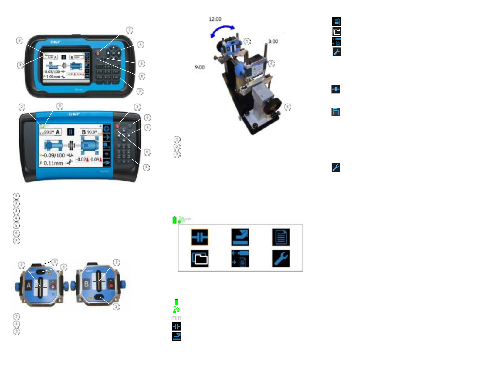
TKSA 60 / 80 Display Units
Power on / off
(hold for two seconds to turn off)
Battery status indicator
Wireless communications status with measuring units
N
avigate display screens and select highlighted item
Cancel (C) bu
tton - delete last character typed
Battery charging LED indicator
Alpha/numeric data entry keypad
TKSA 60 / 80 Measuring Units
Lasers
CCD sensors and sensor grids
Pitch adjustment knob
Measuring unit on the stationary mach
ine
Measuring unit on the movable machine
Movable machine
The above clock positions (9, 12, and 3 o’clock) are the most
common for alignment measurements; however, measurements
can be taken from any clock position. Also, while it is strongly
recommended to take measurements that are 90 degrees apart,
the TKSA 60 / 80 Alignment Tools will accept a minimum rotation
angle of 30 degrees from the previous measurement position.
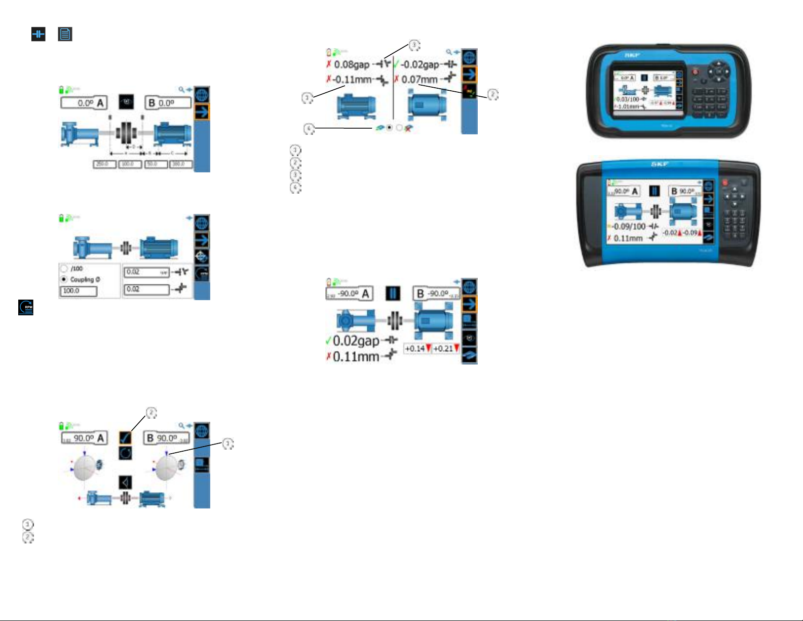
The Display Unit - Home Screen
When first powered on, the Display Unit displays its Home screen.
Icon Description
Display unit’s battery status
Wireless communication status with measuring units
Length units of measurement
Initiate a Quick Alignment
Initiate a Quick Soft Foot job
Set up and perform a Full Alignment job
Open a previously stored alignment job
Export reports to a USB memory stick for transfer to PC
Modify system settings
Two Alignment Method Options
The TKSA 60 / 80 Alignment Tools provide two methods for
performing alignment inspections:
Quick Alignment
The Quick Alignment feature is designed to allow you to quickly
perform an alignment inspection on a motor / pump machine train.
Full Alignment Job
Full alignment jobs require more setup at the beginning of the
alignment job and provide a more structured alignment job
process. Also, you can specify alignment inspections on machine
trains other than motor / pump machine trains, including machine
trains consisting of more than two machines.
To Modify System Settings:
From either the Home screen or the right panel menu, select
the Settings icon to display the main Settings screen. Then specify
Display Unit settings, Measuring Unit settings, Units of
Measurement settings, and Date and Time settings.
Standard Alignment Job Process
Set up the job – Set up the two alignment measuring units; input
machinery dimension information, and alignment targets and
tolerances.
Perform as-found inspections – Perform initial measurements
for the alignment inspection and for other selected inspections.
View results – View as-found inspection results and determine
whether corrections are required for each inspection.
Make corrections - If corrections are required, make corrections
for each inspection requiring correction.
Perform a final as-corrected alignment inspection – After all
corrections are made, re-inspect machine alignment to verify
accuracy and record as-corrected job results.
Save the Job – Save the job for historical reference and for use
with future alignment jobs.
To Perform an Alignment Inspection:
1 – Turn off power to the drive machine.
2 – Attach and adjust the v-brackets and measuring units as
described in the user manual. Laser lines should hit the centre of
the other unit’s white sensor grid.
3 – Power on the measuring units and display unit.

4 – or From the Home screen, select to perform either a
Quick Alignment job or a Full Alignment job.
5 – For Quick Alignment, enter machine dimensions. For Full
Alignment, follow screen prompts to enter machine setup and
inspection selection, then enter machine dimensions.
6 – For Quick Alignment, enter alignment tolerances (targets are
assumed as 0,0). For Full Alignment, targets and tolerances are
previously entered during machine setup.
Provides access to a tolerance table based on machine RPM.
7 – Record three as-found alignment measurements.
Measurements can be taken at any “clock” position, for example:
Reading 1 at 9 o’clock
Reading 2 at 12 o’clock
Reading 3 at 3 o’clock
The sequence of the three measurements should be 9-12-3 or
3-12-9, so that the shafts are always rotated in the same direction
between measurements.
Indicates a previously recorded measurement
Select to record current measurement
8 – View measurement results and specify if corrections are
necessary.
Vertical alignment results
Horizontal alignment results
Coupling position icon
s
Correction / no correction icons
9 – Use live displays to perform required corrections. For vertical
alignment corrections, place the measuring units in the 12 o’clock
position, for horizontal alignment corrections, place the measuring
units in either the 3 o‘clock or 9 o’clock position. Arrowhead
direction indicates direction of movement, arrowhead color
indicates alignment results compared to specified tolerances.
10 - After all alignment values are within tolerances, progress to
measurement screens for any remaining inspections that require
correction.
11 - After performing corrections and recording as-corrected
measurements for any additional inspections, progress to the
alignment Measurement screen, where you measure and record
the final as-corrected alignment.
12 - After reviewing the as-corrected alignment results, press the
right panel’s Next Screen icon to progress to the Save Job screen.
For more information on the above alignment process, and for information
on features and operations not included in this Quick Reference Guide,
reference your TKSA 60 / 80 Alignment Tools User Manual.
SKF offers machinery shims - find them on www.skf.com/alignment.
SKF TKSA 60 / TKSA 80
Shaft Alignment Tools
Quick Reference Guide
This Quick Reference Guide is not a substitute for the product user
manual. It is important that you read the product user manual to
gain a thorough understanding of all product features, operations,
and safety instructions.
SKF Reliability Systems
SKF (U.K.) Limited Condition Monitoring Centre (Livingston)
2 Michaelson Square, Kirkton Campus,
Livingston, UK EH54 7DP
Tel: +44 (0) 1506 470011
Fax: +44 (0) 1506 470012
Web Site: www.skf.com/alignment
P/N 32240200-EN Rev. F02/14 js
Other manuals for TKSA 60
1
This manual suits for next models
1
Other SKF Lighting Equipment manuals
Popular Lighting Equipment manuals by other brands

Maxell
Maxell MSLEDS-10M user manual

Elation
Elation Professional SIXPAR 200IP user manual

Vision & Control
Vision & Control TZB38-B450-P-24V Instructions for use

FlashPoint
FlashPoint MONOLIGHT 320M quick start guide

EuroLite
EuroLite LED ML-20 user manual

Home Accents Holiday
Home Accents Holiday 1002461144 instructions