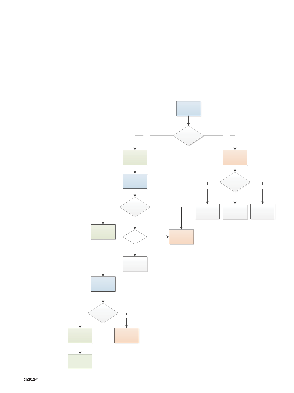
SKF CMON 2504 User manual

CMON 2504
Service manual
The CMON 2504 interface card extends the
functionality of the SKF Multilog On-line
System IMx to include SKF Acoustic Emission
Enveloping (AEE) technology. SKF Acoustic
Emission Enveloping is an acoustic emission
(AE) measurement method that can be used
to assess lubrication conditions within a
rolling element bearing while it is in service.
It can also be used in combination with other
SKF condition monitoring equipment and
techniques to help identify a range of
machinery defects.
Key features
• Enables use of SKF Acoustic Emission
Enveloping technology
• Assessment of lubrication conditions
within rolling element bearings whilst in
service by use of lubrication film
breakdown detection
• Enveloped demodulated AE signal at
100 mV/aeE
•
Enveloping and filtering of 100 to 500 kHz
band pass on AE input
• Two (2) different cable lengths (10 and
20 m) available for the cable assembly
CMON 2504 AE interface card.
CMSS-ONL-2504 cable assembly.

Contents
CMON 2504 and CMSS-ONL-2504 Service Manual
1. Overview
2. Document Conventions
3. CMON 2504 – Card Description
3.1. Key Features
4. CMSS-ONL-2504 – Cable Description
5. CMSS 786M Dual Sensor
6. CMAC 2504 Acoustic Emission Signal Pulse Generator
7. CMON 2504 and CMSS-ONL-2504 Installation Validation and Debugging Procedure
8. Troubleshooting
9. FAQ
1. Overview
The intended audience for this document is Certified Service
Technicians and technical support personnel who provide detailed
technical work to customers, either over the telephone or in person.
It is assumed that these people are already familiar with the SKF
@ptitude Monitoring Suite as well as Microsoft operating systems for
desktop PC. It is also assumed that these people are familiar with
SKF Microlog portable equipment.
The CMON 2504 card provides the necessary interface between
an acoustic emission sensor (specifically the CMSS 786M dual
sensor) and the SKF Multilog On-line System IMx.
The purpose of this document is to provide the information
required to assist users in the installation and commissioning of SKF
Acoustic Emission Enveloping (AEE) systems for the SKF Multilog
On-line System IMx including the following:
• SKF CMON 2504
• CMSS-ONL-2504
• CMSS 786M
2. Document Conventions
The following naming conventions are used throughout this
document. The shorter terms presented on the left below are
synonymous with the corresponding term on the right.
AE Acoustic emission
AEE SKF Acoustic Emission Enveloping
aeE Acoustic Emission Enveloping (units)
IMx SKF Multilog On-line System IMx
Observer SKF @ptitude Observer
Microlog SKF Microlog
3. CMON 2504 – Card Description
The CMON 2504 interface card extends the functionality of the SKF
Mulitlog On-line System IMx to include SKF Acoustic Emission
Enveloping (AEE) technology. AEE is an acoustic emission (AE)
measurement method that can be used to assess lubrication
conditions within a rolling element bearing while it is in service. It can
also be used with other SKF condition monitoring equipment and
techniques to help identify a range of machinery defects. The
CMON 2504 is used with the CMSS-ONL-2504 AE interface cable
assembly. The CMON 2504 can be fitted to a DIN rail.
3.1 Key Features
• Enables use of SKF Acoustic Emission Enveloping technology
• Assessment of lubrication conditions within rolling element
bearings whilst in service by use of lubrication film breakdown
detection
• Enveloped demodulated AE signal at 100 mV/aeE
• Enveloping and filtering of 100 to 500 kHz band pass on AE input
• Two (2) different cable lengths (10 m and 20 m) available for the
cable assembly
4. CMSS-ONL-2504 – Cable
Description
The standard cable assembly includes a pre-amp embedded in the
connector. The cable is intended to be used with the CMSS 786M
dual sensor. The sensor glue mount, which is included with the cable
assembly, should be fixed to the mounting surface using a thin layer
of Loctite 480 epoxy. The use of other epoxies or sensor mounts can
significantly attenuate the AE signal.
2

5. CMSS 786M Dual Sensor
The CMSS 786M is a dual sensor which provides both acceleration
and acoustic emission (AE) input signals. The sensor is mounted
using a sensor glue mount as supplied with the CMSS-ONL-2504.
The sensor glue mount, which is included with the cable assembly,
should be fixed to the mounting surface using a thin layer of Loctite
480 epoxy. The use of other epoxies or sensor mounts can
significantly attenuate the AE signal. The dual sensor is intended to
be used with both the CMSS-ONL-2504 cable assembly and the
CMON 2504 acoustic emission interface card.
6. CMAC 2504 Acoustic Emission
Signal Pulse Generator
The CMAC 2504 is used to inject a known signal into an installation
site. The system response to the signal is used to validate the entire
installation.
The CMAC 2504 generates a pulse train output with 20 V
amplitude, 2.0 μs pulse width, and a repetition frequency of 70 Hz.
To inject a signal, acoustic emission couplant is applied to the
acoustic emission transducer, the transducer is connected to the
CMAC 2504 and the device is turned on. The transducer is then
placed on the test surface (AE sensor or adjacent to AE sensor
installation site).
Before testing with the CMAC 2504 ensure that the AE sensor is
connected to a CMON 2504 card, which should in turn be connected
to an IMx. SKF @ptitude Observer should also be preconfigured to
acquire acoustic emission signals.
Testing the system using the CMAC 2504 is performed using the
CMAC 2504 transducer to inject the signal onto the same flat metal-
lic surface the AE sensor is installed on, ensuring it is free of paint or
residue. Ensure there is a direct transmittance path between the
CMAC 2504 transducer and the AE sensor (i.e., no cracks/joints/nuts/
bolts, etc., interrupting the path).
The system response for both steps should be viewed in SKF
@ptitude Observer (“live” mode is recommended). The system re-
sponse should be an attenuated pulse train with the same repetition
frequency (~70 Hz).
If the system response is not as expected, check the following:
• The AE sensor is fixed and secured on its installation site
• There is acoustic emission couplant on both the AE sensor and the
CMAC 2504 transducer
• There are no cracks/joints/nuts/bolts interrupting the transmit-
tance path between CMAC 2504 transducer and AE sensor
• The cable is connected to the AE sensor
• If none of the above resolve the issue, perform testing using the
digital voltmeter
Fig. 1. CMAC 2504 and transducer.
3

Fig. 2. CMON 2504 wiring diagram – IMx-S
Fig. 3. CMON 2504 wiring diagram – IMx-W
CMON 2504
J1J3
J2
Ch1
PAB
100110
gE
100100
Ch2
PAB
AEE
PAB
Chx
PAB
Chx
PAB
Chx
PAB
Chx
PAB
Chx
PAB
Chx
PAB
Chx
PAB
Chx
PAB
Chx
IMx-S
J2-3
J2-2
J2-1
J3-3
J3-2
J3-1
J1-3
J1-2
J1-1
xx
Black
Blue
Green
Red
Cable screen
Chassis ground bar
To CMSS 786M sensor
x
CMON 2504
J1J3
J2
Ch1
+-
gE
Ch2
+-
AEE
+-
Chx
IMx-W
J2-3
J2-2
J2-1
J3-3
J3-2
J3-1
J1-3
J1-2
J1-1
xx
Black
Blue
Green
Red
Cable screen
Chassis ground bar
To CMSS 786M sensor
x
+-
Chx
+-
Chx
+-
Chx
+-
Chx
+-
Chx
+-
Chx
+-
Chx Ch1
D0
Relay driver
Ch2
+12V D0 +12V
H
CAN
CAN
GND
CAN
L
CAN A
RS485
GND
B
4

7. CMON 2504 and CMSS-ONL-2504 Installation Validation and
Debugging Procedure
The following procedure can be used to identify the source of a malfunctioning AEE installation. This procedure is also required prior to the
commissioning of an installation and can therefore be considered standard procedure.The procedure is outlined in flowchart format and only
a digital voltmeter is required.
Note that the following nomenclature (J1-1, etc.) is used when referring to the CMON 2504 terminals (Input + etc.).
• J1-1: AE sensor signal / phantom power line (Input +)
• J1-2: AE sensor 0 V return (Input –)
• J1-3: not used
• J2-1: +12 to +24 V DC power supply input (Supply +)
• J2-2: 0 V DC power supply input and signal ground (Supply –)
• J2-3: not used
• J3-1: AE DIN interface demodulated output (Output +)
• J3-2: not used
• J3-3: Signal ground (Output –)
Check power
supply
Check wiring Check wiring and
IMx DIP settings
IMx-W
IMx-S
Check wiring
External supply
Low Power
Measure voltage
across J2-1 and J2-
2
< 11V
Power OK
>11V
1. Check CMON
2504 Power
Supply
2. Check CMON
2504 input
Measure voltage
across J1-1 and J1-
2
Sensor & cable OK
>6.9V & <7.1
Cable fault
>7.1V
<6.9V
3. Check CMON
2504 output
Measure voltage
across J3-1 and J3-
3
CMON 2504 OK
<0.1V
CMON 2504
fault / bad power
ground
>0.1V
Correct the
polarity
Check cable
polarity
Polarity wrong
Polarity OK
Proceed to CMAC
2504 testing
Fig. 4. Installation validation and debugging flowchart for CMON 2504
installations. Terminal voltages to be measured using a digital voltmeter
(DVM) or a multimeter.
5

8. Troubleshotting
Fault
Incorrect polarity of CMSS-ONL-2504 cables at Input terminals to
CMON 2504
Effect
If the polarity of the input wires to the CMON 2504 is incorrect then the
output signal will be low in amplitude and should show little if any response
to testing using the CMON 2504. The voltage across the input terminals
(as determined by the debugging flow chart) will be less than 6.9 V.
Corrective Measure
Swap the input wires to the CMON 2504. Using the debugging flowchart
as a guide, check the CMON 2504 terminal voltages. The voltage across
the input terminals should be between 6.9 V and 7.1 V. Confirm the system
is functioning correctly by testing with the CMAC 2504.
Fault
Low power
Effect
Little if any meaningful signal being acquired by IMx as CMON 2504 cards
not receiving sufficient power.
Corrective Measure
• Check that the connections between the power supply and the
CMON 2504 are correct and that the power supply is configured to
supply the correct input voltage (i.e., >11 V). Correct if necessary.
• Check that the screw terminals in the CMON 2504 are gripping only the
metal part of the wires and not the wire insulation. Correct if necessary.
• If the IMx is an IMx-S, then check that the DIP switch settings are
correct. If not, then power off the IMx unit and correct the DIP switches
as appropriate.
Fault
Poorly connected wires in CMON 2504
Effect
Severely degraded signal acquired by IMx. Little if any meaningful data
acquired.
Corrective Measure
Check that the screw terminals in the CMON 2504 are gripping only the
metal part of the wires and not the wire insulation. Correct if necessary
Ensure that all wires are connected as specified.
Fault
Cable fault
Effect
Severe degradation of sensor signal.
Corrective Measure
Check all wire connections and ensure that there is no short-circuiting of
wires due to frayed wire ends, etc. If this does not resolve issue, then
replace the CMSS-ONL-2504 cable and return faulty cable to SKF CMC
Livingston.
Fault
Electrical noise (mains interference) evident in signal
Effect
Excess electrical noise can lift the noise floor and can mask interesting low
amplitude acoustic emission activities. This manifests itself at 100 Hz or
120 Hz peaks in the spectrum depending on whether the local mains
frequency is 50 Hz or 60 Hz.
Corrective Measure
The following measures are part of the recommended installation process.
1. Ensure that the negative output terminal (J3-3) is connected to the
ground rail on the IMx chassis.
2. The sensor shield should only be grounded at one end – due to the
installation process of the CMSS 786M dual sensor – it is not assured
that the sensor is grounded at the machine end, therefore it is
recommended to try connecting the CMSS-ONL-2504 shield to the IMx
ground to see if this reduces the electrical noise.
3. Is a Vogel lubrication system (or similar) connected into the IMx? If the
IMx is an IMx-W, then the lubrication system may be the source of
electrical mains hum in adjacent channels. To correct this, it is
recommended to use channel 15 and channel 16 of the IMx-W for the
lubrication system and to use the associated DIP switches to isolate
these channels (set switches to 1100 and refer to IMx-W manual for full
isolation details).
4. Check that the machine being instrumented is grounded. If it is not
possible to earth the machine, then it is recommended that you contact
SKF CMC Livingston for guidance with corrective measures.
Fault
CMON 2504 fault
Effect
Severe degradation of sensor signal.
Corrective Measure
Replace the CMON 2504 card and return faulty card to SKF CMC
Livingston.
Fault
No response to CMAC 2504 test stimulus
Effect
System cannot be validated.
Corrective Measure
1. Tap the sensor sharply (taps need only be light) and observer response.
This should identify if the CMAC 2504 is defective or if it is indeed the
installation.
2. If no response still from the system, then check CMON 2504 installation
using a voltmeter and the attached flowchart. Check all wire connections
and refer to the installation manual to confirm correct installation.
3. Check that software configuration and settings are correct and that a
signal from the sensor is being acquired.
6

Fault
AE sensor installed at inappropriate location
Effect
AE signal quality not assured.
Corrective Measure
• Reinstall sensor at an appropriate location.
• The optimum location is in the load zone of the bearing. Ensure it is not
located close to any surface discontinuities such as boltholes. Also
ensure that the transmission path between AE source and sensor as
direct as possible (keep number of surface interfaces to a minimum).
Note thatAE does not travel through air, therefore if there is an air gap
between sensor location and AE source then no relevant signal will be
obtained.
Fault
AE sensor installed incorrectly using:
(a) the wrong adhesive
(b) the wrong mounting method
(c) with insufficient preparation of installation site
Effect
AE signal either attenuated or completely killed.
Corrective Measure
• If using an adhesive sensor mount, then install a new adhesive sensor
mount. Ensure that all paint has been removed from beneath the sensor
and that the sensor mount will be stuck onto a metallic surface.
• Use Loctite 480 to stick the sensor mount to the installation site – the
sensor mount should only be glued to metallic surfaces, therefore all
paint needs to be removed beneath.
• Remount the sensor, ensuring that the sensor is sufficiently coupled
with the sensor mount using an appropriate couplant (Sonotech Sono
600 for very short term installations or Marine Silicone Sealant for
longer term installations).
• If using a stud mount, ensure that sensor is sufficiently coupled using an
appropriate couplant (Sonotech Sono 600 for very short term
installations or Marine Silicone Sealant for longer term installations).
9. FAQ
What is the product?
It is an Acoustic Emission Enveloping (AEE) Interface that
demodulates a specific frequency band of Acoustic Emission (AE) so
that standard Condition Monitoring analyzers can acquire and
analyze Acoustic emissions for the purpose of monitoring the
lubrication quality in bearings.
What is unique about the product?
It utilizes a specific frequency band specifically selected to be
sensitive to AE noise from bearing lubrication issues and less affected
by high frequency vibrations or electrical interference.
What are the features?
A 100 kHz to 500 kHz frequency band and enveloping with a 5 kHz
anti-aliasing filter proving an output of 100 mV per aeE.
What are the benefits?
Provides a method of monitoring for bearing lubrication quality and
issues that is far more sensitive than other techniques currently on
the market. This allows for the lubrication issue to be corrected prior
to damage occurring to the bearing.
What is different from previous SKF products? From
competitors products?
With respect to SEE, improved amplification, filters and
rectification improving the signal to noise ratio and allowing
accurate measurements down to lower amplitudes. With respect
to Holroyd, a higher frequency band and a high-pass filter to avoid
picking up high frequency vibration.
In what segments/products/vehicles/models are the SKF
products/service used?
Wherever IMx units are utilized to monitor high value bearings or
equipment and/or there is a business case to monitor for and
correct lubrication issues.
Is there a relationship between AE and sub-surface cracking?
Yes, there is a relationship and in a controlled environment this can
be easily detected. This is less easy to do in an industrial
environment. We cannot however differentiate between sub-
surface cracking, a spall progressing or asperity contact.
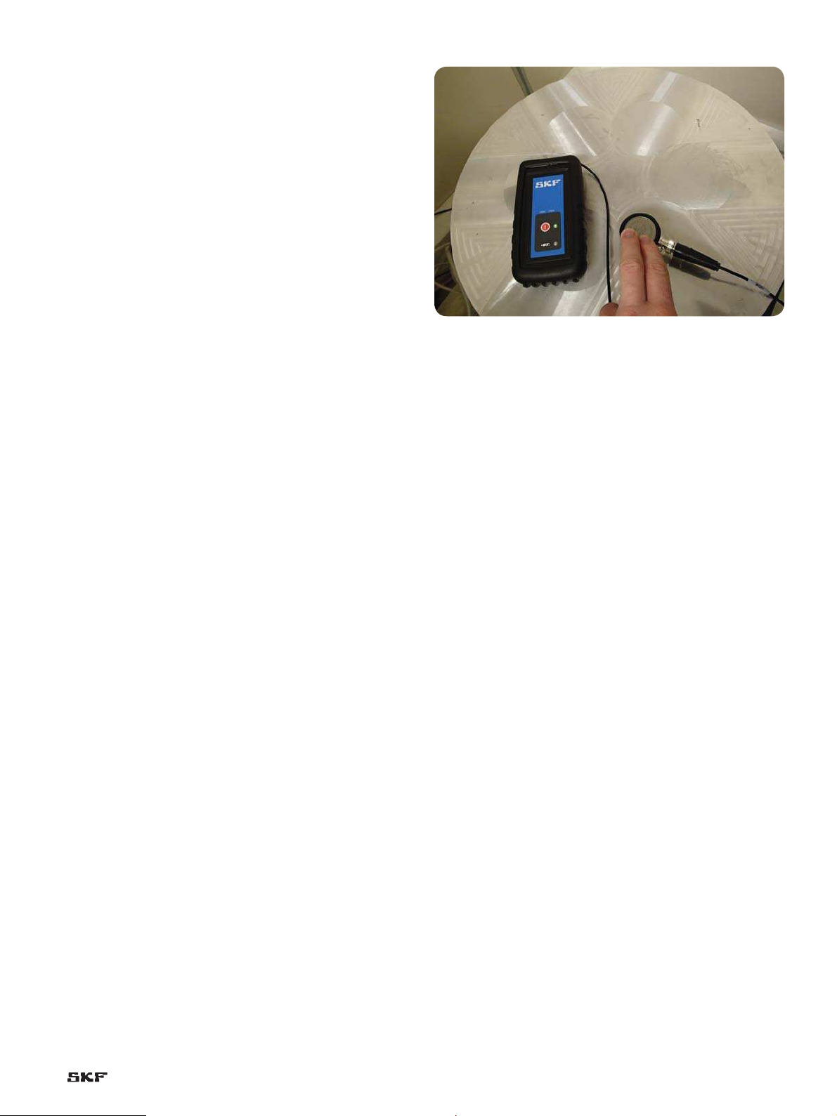
Should the sensor be mounted near a load zone to get a good
signal?
Yes, the sensor should be located as close to the load zone as
possible.
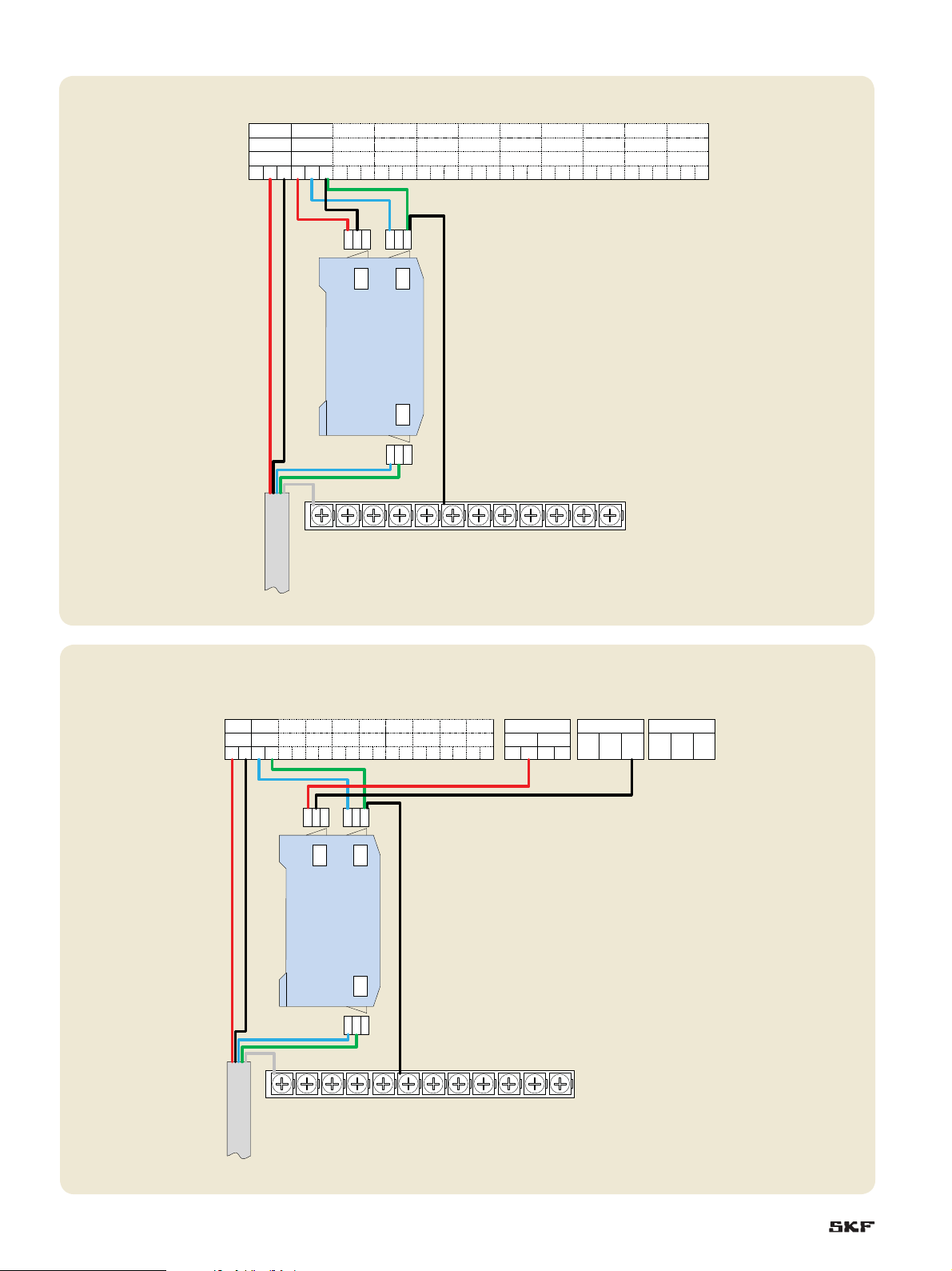
J3-3 should be connected to IMx ground. Should this be the
digital instrument ground or the chassis ground?
The IMx chassis ground should be used.
How many of the converters can we connect to the +12 V
power of the IMx-W?
Up to three CMON 2504 can be connected to each relay, so a
maximum of six CMON 2504 can be powered from IMx-W. If more
than six CMON 2504 are to be used in an IMx-W, or if relays are in
use for another product, then a DIN rail mounted power supply
should be used.
Is there a limit to the number of CMON 2504 that can be used
in IMx-S?
Each CMON 2504 in an IMx-S is powered from the channel that it
is connected to, so the only limitation in the number that can be
connected in the IMx-S is physical – i.e., how many can be fitted
onto the DIN rail.
Does the use of a 12 V powered speed sensor influence the
signal from the CMON 2504?
Yes, the use of a speed sensor does influence the signal. To avoid
this, the cable screen should be connected to the IMx chassis
ground.
Is it possible to use a magnet to mount the sensor rather than
having to remove the paint?
No, the magnet attenuates the AE signal so is not suitable for
mounting the sensor.
7

Please contact:
SKF Condition Monitoring Center – Luleå
Aurorum 30, SE-977 75 · Luleå, Sweden
Tel: +46 (0)31 337 1000 · Fax: +46 (0)920 134 40
Web: www.skf.com/cm
®SKF, @PTITUDE, MICROLOG and MULTILOG are registered trademarks of the SKF Group.
Microsoft is a registered trademark of Microsoft Corporation in the United States and/or other
countries.
Loctite is a registered trademark of Henkel Corporation.
All other trademarks are the property of their respective owners.
©SKF Group 2014
The contents of this publication are the copyright of the publisher and may not be reproduced (even
extracts) unless prior written permission is granted. Every care has been taken to ensure the accuracy
of the information contained in this publication but no liability can be accepted for any loss or damage
whether direct, indirect or consequential arising out of the use of the information contained herein.
PUB CM/I3 14117 EN · May 2014
Seals Bearings and
housings
Lubrication
systems
Mechatronics Services
The Power of Knowledge Engineering
Combining products, people, and application-
specific knowledge, SKF delivers innovative
solutions to equipment manufacturers and pro-
duction facilities in every major industry world-
wide. Having expertise in multiple competence
areas supports SKF Life Cycle Management, a
proven approach to improving equipment reliabil-
ity, optimizing operational and energy efficiency
and reducing total cost of ownership.
These competence areas include bearings and
units, seals, lubrication systems, mechatronics,
and awide range of services, from 3-D computer
modelling to cloud-based condition monitoring
and asset management services.
SKF’s global footprint provides SKF customers
with uniform quality standards and worldwide
product availability. Our local presence provides
direct access to the experience, knowledge and
ingenuity of SKF people.
Why is it so important to remove all the paint before mounting
the sensor?
It is important to remove the paint to ensure that the sensor has a
good connection and AE transmission path. The layers of paint can
both attenuate the AE signal and also electrically isolate the sensor
from the machine.
Loctite 480 is recommended for mounting if a drilled and tapped
hole is not available. This is a rubber filled epoxy. Does that
negatively affect the acceleration ENV readings?
No, the rubber is very good for AE signal transmission and the layer
of epoxy is thin enough to not impact the gE signal.
Is it necessary to scrape the paint off the position where the
CMAC 2504 transducer will be placed for installation
verification?
It would be better to remove the paint, but it is not necessary as the
AE signal gets through the paint well enough for this simple test, and
also because we don’t need the electrical grounding which the paint
prevents with the sensor installation.
Is it important to ensure that the glue fills all the gaps?
Yes, this is important as AE cannot travel through air, so any air gaps
will attenuate the signal. However, as little epoxy should be used as
possible.
skf.com
Table of contents
Other SKF Recording Equipment manuals